1996 HONDA CIVIC battery
[x] Cancel search: batteryPage 451 of 2189
PGM-FI System
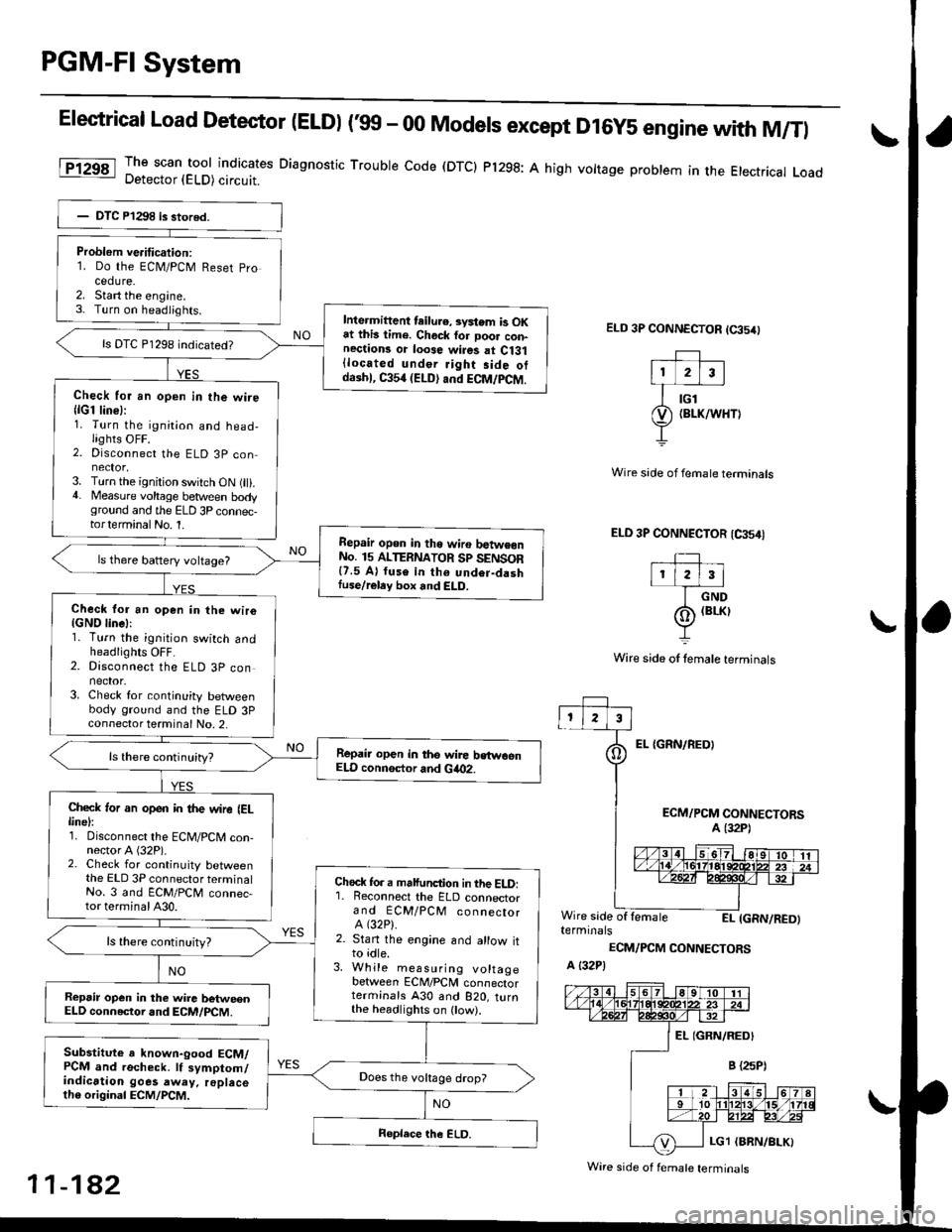
Elestrical Load Detector (ELDI ('99 - 00 Models except D16y5 engine with M/Tl
The scan tool indicates Diagnostic Trouble code (DTCI Pl298: A high vottage problem in the Etectrical LoadDetector (ELD) circuit.
ELD 3P CONNECTOR (65/0
EL {GRN/REOI
Wire side of fernale terminals
ELD 3P CONNECTOR (CA54I
TIr l2l3l
I crvo
(o) (BrKr
Y
Wire side of lemale terminals
ECM/PCM CONNECTORSA (32P1
Wire side of lemaleEI- IGRN/RED)terminals
ECM/PCM CONNECTORS
A {32P)
Problem ve.itication:1. Do the ECN4/PCM Reset pro
cedure.2. Start the engine.3- Turn on headiights.Inte.mittent teilu.e, svstem is OKat this lime. Chock for Door con-nections or loose wires at Ci31{located under Jight side otdaihl, C354 (ELD) and ECM/PCM.
ls DTC P1298 indicated?
Check for an open in the wire{lG1 line}:1. Turn the ignition and head-lights OFF.2. Disconnect the ELD 3P con
3. Turn the ignition switch ON (ll).4. Measure voltage between bodyground and the ELD 3P connec-torterminalNo. 1.
Repair opon in tho wiro batwe€nNo. 15 ALTERNATOR Sp SENSOR{7.5 A} fuse in th6 undor-dashIuse/reley box and ELD.
ls there battery voltage?
Check for an open in the wiro{GND linel:1. Turn the ignition switch andheadlights OFF.2. Disconnect the ELD 3P connector.3. Check for continuity betweenbody ground and the ELD 3Pconnector terminal No. 2,
Repair open in the wire bstwoenELD connsctor and Gia02.
Check ,or an open in the wire IELlinel:1. Disconnect the ECM/PCM con-nector A (32P).2. Check for continuity betweenthe ELD 3P connector terminalNo. 3 and ECM/PCM connec-tor terminal A30.
Chock fo. a malfunction in the ELD:'1. Reconnect the ELD connectorand ECM/PCM connectorA (32P).
2. Stan the engine and allow itto idle.3. While measuring voltagebetween ECM/PCM connectorterminals A30 and B2O, turnthe headlighrs on ow).
ls there continuity?
Repsir op€n in the wire betweenELD connector and ECM/PCM.
Substitute a known-good ECM/PCM and recheck. lf symptom/indication goes away. replacelh6 original ECM/PCM.
Does the vokage drop?
Wire side of f€male terminals
11-182
Page 458 of 2189

[F16551l Th" ""un toot indicates Diagnostic Trouble Code (DTC) P1681: TIVA,/TMB signal line failure
Problem verification:1. Do the ECM Reset Procedure.
2. Drive the vehicle Ior several
miles at varying speeds
lnt.rmittent failure, system is OK
at ihis time. Check tor Poor con-
nections or loos€ wires at C131
llocated under right side of dash),
C438 ITCM) and ECM.
ls DTC P1655 indicated?
Check lor an oPen in the wire(TMA line):1. Turn the ignition switch OFF
2. Disconnect ECM connector C(31P)from the ECM
3. Turn the ignition switch ON (ll).
4- Measure vo ltag e between
ECM connector terminal Cg
and body ground.
Check for a short in the wire
ITMA line,:Measure voltage between TCM
22P connector terminal No 7 and
body ground.ls there battery vohage?
Ropair shod in the wire bstwe€n
the EcM (C!l) and the TcM.ls there battery voltage?
Check for an open in the wire
{TMB line}:1. Turn the ignition switch OFF
2. Reconnect ECM connector c(31P).
3. Disconnect the 22P connector
from TCM.4. Turn the ignition switch ON (ll).
5. Measure vo ltage between
TCM 22P connector termlnal
No. 6 and body ground.
Repair open in the wire between
th€ EcM {Ca) and the TcM.
Check for a 3ho.t in the wire
{TMB lin6,:Measure voltage between ECM
connector terminal C30 and bodyground,
ls there battery voltage?
Substitute a known'good ECM
and recheck. It symPtom/indica'tion goes away, teplace the origi-
nal ECM.
Reoair short in the wile b6tween
the ECM {C30} and the TCM.ls there baftery voltage?
f,epair open in the wire between
the EcM (C30) and the TcM.
IJA/T Signal (TMA/TMBI ('96 - 98 Dl6Y5 engine with GW)
ECM CONNECTOR C 131P}TMA IGRYI
fcu22PCONNECTOR
ll
TMB*{PNK}
231678910
1t'12131415161718
232a252930
Wire side oI temale
terminals
tl,
1 1-189
Page 466 of 2189
t
I
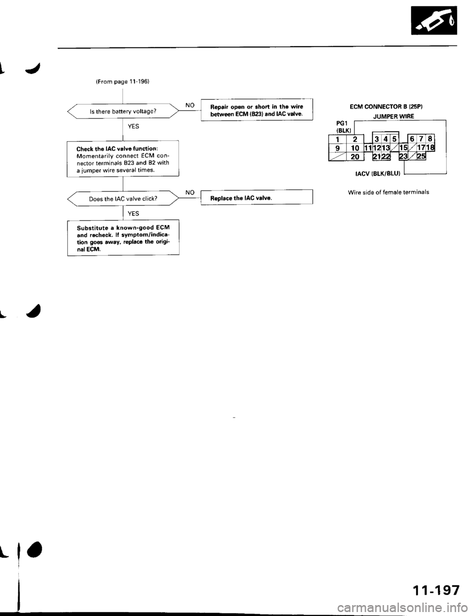
{From page 11-196)
Repair opon or short in lhe wire
between EcM lBzl) and lAc valve.ls there battery voltage?
Check the IAC valve fundion:Momentarily connect ECM con-
nector terminals 823 and 82 with
a iumpe. wire several tames.
Does the IAC valve click?
Substitute a known-good ECM
and rocheck. ll symptom/indicd-tion go€s away, rePlace tho origi_
nal ECM.
Wire side of female terminals
11-197
Page 477 of 2189

ldle Control System
Alternator (ALTI FR Signal {'96 - 98 Models,'99 - 00 Dl6y5 engine with M/Tl
ECM/PCM CONNECTORS
a {32P)
LGl(BRN/BLK)
Wire side of female terminals
ALT CONNECTORS IC1O4I
JUMPER
JUMPER WIRE
WIRE
Wire side of female terminals
ALT F{WHT/REO)
This signals the ECM/PCM when the Alternator (ALT) is charging.
Inspoction of ALT FR Signal.
Check tor a short in tfte wire (ALTF linel:1. oisconnect the 4P (3P)* con-nector from the ALT.2. Turn the ignition switch ON (ll).3. M easu re voltage betweenECM/PCM connector terminals C17 and A9.Check lor a sho.t in the wire {ALTF line):r. I urn rne tgn|lton swtlch ul-f,2. Disconnect the negative bat-tery cable from the baftery.3. Disconnect the ECM/PCM connector C {31P).4. Check for continuity betweenbody ground and ECM/PCMconnector terminal C17.
ls there approx. 5 V?
Check th€ operation of the ALT:1. Turn the ignition switch OFF.2. Reconnect the ALT 4P (3P)*connector to the ALT.3. Start the engine. Hold theengine at 3,000 rpm with noload (in Park or neutral) untjlthe radiator fan comes on, thenlet it idle.4. [,4easu re voltage betweenECM/PCM connector terminalsC17 and A9.
Repair short in the wire betwe€nthe ECM/PCM {Cl71and th€ ALT.
Substitute a known-good ECM/PCM and recheck. It prescribedvoltage is now available, roplacethe originrl ECM/PCM.
Does the voltage decrease whenheadlights and rear defogger areturned on?ALT FR signal is OK.
Check tor an open in the wire (AlTF linel:1. Turn the ignition switch OFF.2. Disconnect the negative bat-tery cable from the battery.3. Disco n nect the ECM/PCMconnector C (31P).4. Disconnect the 4P (3P)* con,nector from the ALT.5. Connect the ALT 4P 13P)l connector terminal No. 4 (No. 1)'to body ground with a iumper
6. Check lor continuity betweenbody ground and ECM/PCMconnector terminal C17,
Repair op6n wire botween th€ECM/PCM (C171rnd th€ ALT.ls there continuity?
c {31P)
1178I10
1112131415161718
232125a30
oALT F IWHT/REDI
4P3P*
1 2l
Flr
rr-ri-frwHr/ (V)
neor Y
*: Canada model
11-208
3I78910
1l1213l415161718/l
232125E30
oALT F IWHT/REDI
Page 478 of 2189

tAlternator (ALT) FR Signal ('99 - 00 Models except Dl6Y5 engine with M/T)
This signals the ECM/PCM when the Alternator {ALT) is chargingECM/PCM CONNECTORS
Wire side of female terminals
ECM/PCM CONNECTOR C (31P}
lt
lP
ALT CONNECTORS IClO4I
JUMPER
JUMpER WlnE
WIRE
Wire side of female termlnals
ECM/PCM CONNECTOR C (31PI
3P*NO
Check lor an op€n in the wire (ALT
F line,:1. Turn the agnition switch OFF
2. Disconnect the negative bat-
tery cable {rom the battery.
3. Disconnect the ECM/PCM con'
nector C (31P).
4. Disconnect the 4P (3P)* con'
nector from the ALT.
5. Connect the ALT 4P (3P)* con-
nector terminal No 4 (No. 1)*
to bodY ground with a iumper
6. Check lor continuity between
body ground and ECM/PCM
connector terminal C5
--?--1l2l|�#i3l.l
otriJrwxrr (V)
neor Y
lnsoeclion oI ALT FB Signal.
Check {or a short in the wire {ALT
F line):1. Disconnect the 4P (3P)+ con
nector from the ALT
2. Turn the ignition switch ON (ll)
3. Measurc voltage between EcM/
PCM connector terminals C5
and 820.Check tor a short in the wirc (ALt
F line):1. Turn the ignition switch OFF
2. Disconnect the negative bat_
tery cable from the baRery'
3. Disconnect the ECM/PCM con'
nector C (31P).
4. Check for continuity between
body ground and ECM/PCM
connector terminal C5
ls there aPProx. 5 V?
Check the operation otthe ALT:
1. Turn the ignition switch OFF.
2- Reconnect the ALT 4P (3P)*
connector to the ALT
3. Start the engine. Hold the
engine at 3,000 rpm wrth no
load {in Park or neutrali until
the radiator fan comes on,
then let it idle.
4- Measure voltage between ECM/
PCM connector terminals C5
and 820.
Repair short in the wire between
the EcM/PCM {C5l and the ALT.
Substitute a known-good ECM/
PCM and rechock. lf P.esc.ibedvoltage is now availabl€, ieplace
tho original ECM/PCM
Does the voltage decrease when
headlights and rear delogger are
turned on?
ALT FF signal is OK.
Repair oPen wire betwoen t|lo
ECM,/PCM {C5) and the ALT.
ALT F (WHT/RED)
Wire side of temale terminals
*: Canada model
Wire side of female termrnals
Page 479 of 2189
ldle Control System
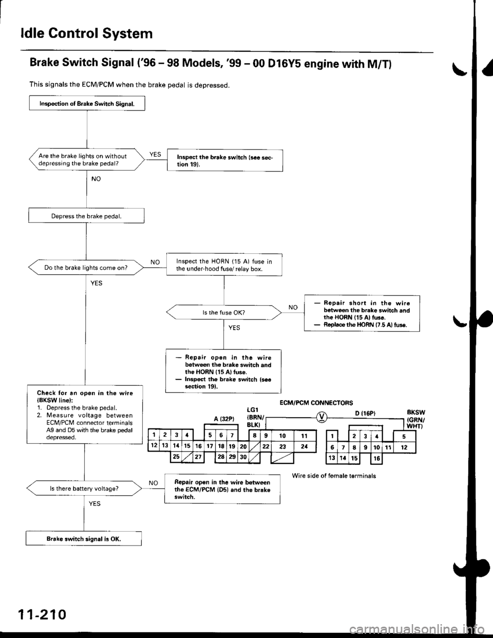
Brake Switch Signal ('96 - 98 Models, '99 - 00 Dl6YS engine with M/Tl
This signals the ECM/PCM when the brake pedal is deoressed.
LGlBKSW(GRN/WHTI
D {16P)
Wire side of female t€rminals
Inspection of Brake Switch Signal.
Are the brake lights on withoutdepressing the brake pedal?
Depress the brake pedal.
Inspect the HORN (15 A) fuse inthe under-hood fuse/ relay box.Do the brake lights come on?
- Repair short in the wirebetween the brake 3whch andrhe HORN 115 At lu3e.- Replace the I|oRN 17.5 A) tus€.
Repair open in the wirebetween the brake switch andthe HORN 115 Al fuse.Inspect th6 br.ke switch {s6€section l9l.Check tor an open in the wireIBKSW line):1. Oepress the brake pedal.2. Measure voltage betweenECM/PCNI connector terminalsAg and D5 with the brake pedaloepresseo.
Repair open in the wire b€tweenthe ECM/PCM {Dsl and the brakeswitch.
ls there battery voltage?
Brakc switch sign.l is OK.
ECM/PCM CONNECTOFS
A (32PtIBRI\v
,la678101112I
121311151617t8192022232aI9101112
25212Aa3013141516
11-210
Page 481 of 2189
ldle Control System
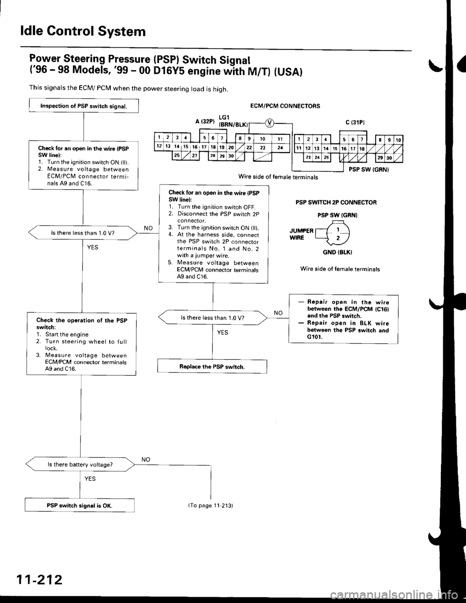
lgy"t9!"_"ring Pressure (PSPI Switch Signal
('96 - 98 Models, '99 - 00 DlGy5 engine witn fU/f) (USAI
This signals the ECM/ PCN4 when the power steering load is high.
ECM/PCM CONNECTORS
PSP SWITCH 2P CONNECTOR
PSP SW IGRNI
JUMPER l--L I IwfRE -2/
GND (BLKI
Wire side ol female terminais
Inspection o{ PSP switch signal.
Check for an opon in the wire {PSPSW linelr1. Turn the ignition switch ON (ll).2. Measure voltage betweenECM/PCM connecror termi-nals A9 and C16.
Check lor an open in the wire (PSPSW line):1. Turn the ignition switch OFF.2. Disconnecl the PSP switch 2p
3. Turn the ignition switch ON (ll).4. At the harness side, connectthe PSP switch 2P connectorterminals No. l and No.2with a jumper wire.5. Measure voltage betweenECM/PCM connector terminalsAg and C16.
ls there lessthan 1.0 V?
- Repair open in the wirobetween the ECM/PCM lc16land the PSP switch.- Repair open in BLK wirebetwoen the PSP switch andG101.
ls there less than 1.0 V?Check the operation of the PSPswitch:'1. Start the engine2. Turn steering wheel to full
3- Measu re voltage betweenECM/PCM connector terminalsA9 and C16.
ls there battery voltage?
PSP switch signel is OK.
Wire side oI temale terminals
11-212
(To page 11'2'13)
Page 482 of 2189
t
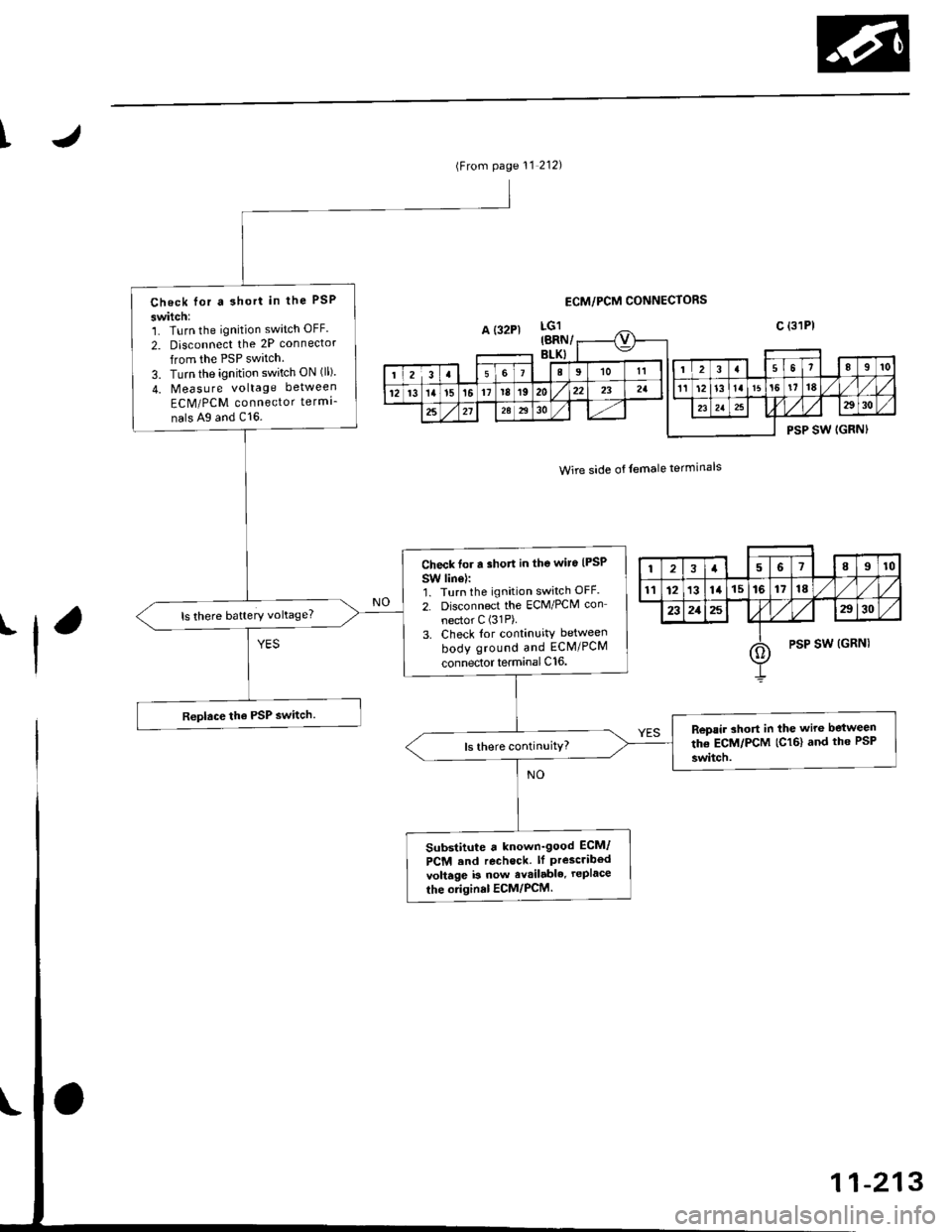
(From page 11 212)
Check lor a 3hort in the PSP
switch:1. Turn the ignition switch OFF.
2. Disconnect the 2P connector
from the PSP switch.
3. Turn the ignition switch ON (ll)
4. Measure voltage between
ECM/PCM connector termi-
nals Ag and C16.
Check tor a short in the wiro {PSP
SW linel:'1. Turn the ignition switch OFF.
2. Disconnect the ECM/PCM con
nector C (31P).
3. Check lor continuity between
body ground and ECM/PCM
connector terminal C16.
ls there battery vohage?
Repair ahort in the wire between
the ECM/PCM (C16) and th6 PsP
switch.
Substitute a known_good ECM/
PCM end rechock. lf Prescribedvoltage b now avsilable. rePlace
the original ECM/PCM.
ECM/PCM CONNECTORS
Wire side of temale terminals
'l
12a6189t0
tl12131415161718
232125a30
oPSP SW (GRNI
1-213