Page 1005 of 2189

Secondary Gear Shaft
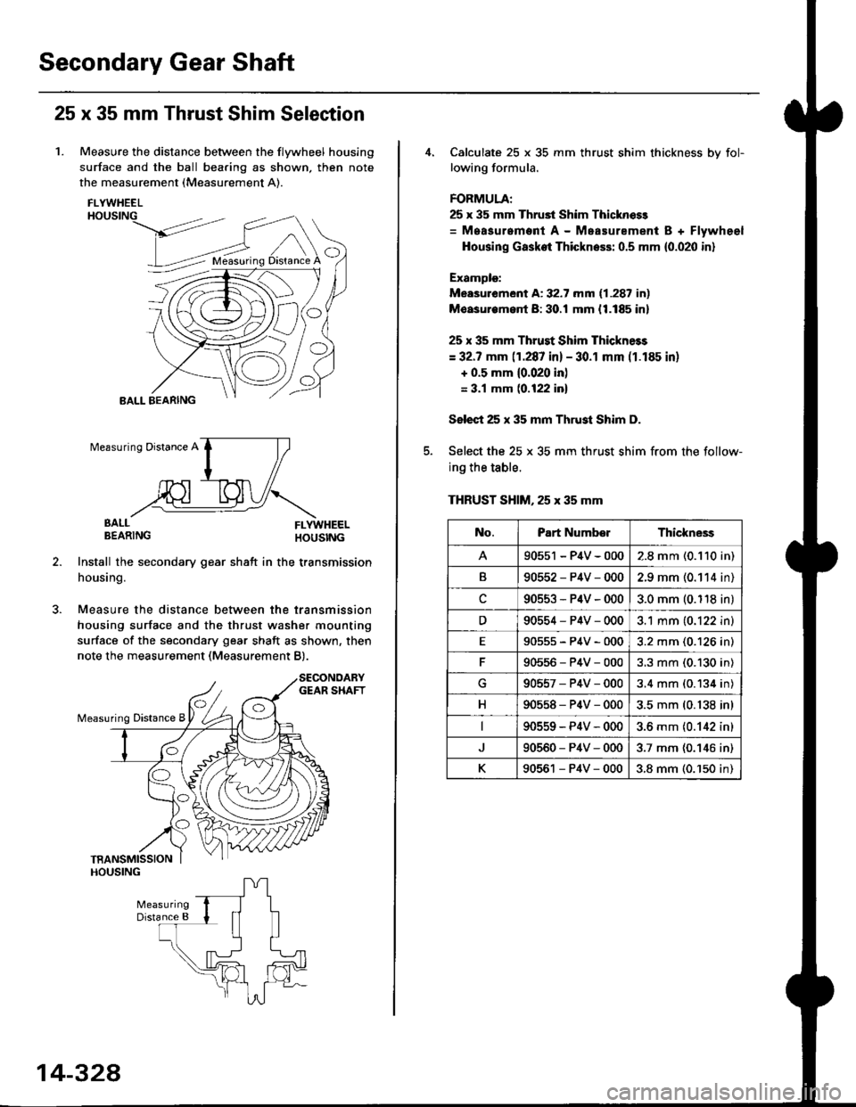
25 x 35 mm Thrust Shim Selection
1. Measure the distance between the flywheel housing
surface and the ball bearing as shown, then note
the measurement (Measurement A).
FLYWHEELHOUSING
>dt?'
BALL BEARING
EALL FLYWHEELBEARING HOUSTNG
Install the secondary gear shatt in the transmission
housing.
Measure the distance between the transmission
housing surface and the thrust washer mounting
surface of the secondary gear shaft as shown, then
note the measurement (Measurement B).
O
Measuring Distance A
BALL
14-328
Calculate 25 x 35 mm thrust shim thickness bv fol-
lowing formula.
FORMULA;
25 x 35 mm Thrust Shim Thicknoss
= Measurement A - Measurement B + Flywheel
Housing Gasket Thickness: 0.5 mm {0.020 in}
Example:
Measurement A: 32.7 mm (1.287 in)
Moasurem.nt B: 30.! mm {1.185 in}
25 x 35 mm Thrust Shim Thickness
= 32.7 mm (1.287 in) - 30.1 mm (1.185 in)
+ 0.5 mm {0.020 in)
= 3.1 mm (0.122 inl
Select 25 x 35 mm Thrust Shim D.
Select the 25 x 35 mm thrust shim from the follow-
ing the table.
THRUST SHIM, 25 x 35 mm
No.Part NumberThickne3s
90551 - P4V - 0002.8 mm (0.110 in)
B90552-P4V-0002.9 mm (0.114 in)
c90553-P4V-0003.0 mm (0.118 in)
D90554-P4V-0003.1 mm (0.122 in)
E90555-P4V-0003.2 mm (0.126 in)
90556-P4V-0003.3 mm (0.130 in)
G90557-P4V-0003.4 mm (0.134 in)
H90558-P4V-0003.5 mm (0.138 in)
90559-P4V-0003.6 mm {0.142 in)
90560-P4V-0003.7 mm (0.146 in)
K90561 - P4V - 0003.8 mm (0.'150 in)
Page 1008 of 2189
l.
Oil Seal Removal
Remove the differential assembly.
Remove the oil seal from the transmission housing.
1.
2.
TRANSMISSONHOUSING
OIL SEALR€placa.
3. Remove the oil seal from the flywheel housing.
Oil Seal Installation/Side Clearance
1. lnstall a 2.50 mm (0.098 in) thick 80 mm wide set
ring in the transmission housing.
NOTE: Do not installthe oil seal yet.
TRANSMISSIONHOUStl{G
lnstall the differential assembly into the transmrs-
sion housing using the specialtool as shown
DIFFEREI{NALASSEMBLY(cont'd)
14-331
Page 1009 of 2189
Differential
Oil Seal Installation/Side Clearance (cont'dl
3. Installthe flywheel housing, and tighten the bolts.
DOWEL PIN
1 .25 mmN m (3.0 kgt m,22 lbf.ttl8x29
uigE
14-332
4. Measure the clea.ance between the 80 mm set ring
and outer race of the ball bearing in the transmis-
sion housing.
STANDARD: 0 - 0.15 mm (0 - 0.006 in)
lf the clearance is more than the standard, select a
new set ring from the table, and install it.
SET RING, 80 mm
NOTE: lf the clearance measured in steD 4 is stan-
dard, it is not necessary to perform steps 7 and 8.
Remove the flywheel housing.
Replace ttle 2.50 mm (0.098 in) set ring, 80 mm with
the one ot the correct thickness selected in steD 5.
6.
7.
Part NumberThickness
904'�r4-689-000
90415-689-000
90416-689-000
90417-689-000
90418-689-000
90419-PH8-000
2.50 mm (0.098 in)
2.60 mm (0.102 in)
2.70 mm (0.106 in)
2.80 mm (0.110 in)
2.90 mm (0.114 in)
3.00 mm (0.118 in)
Page 1010 of 2189
Flywheel Housing
Input Shaft Oil Seal
l.
8. Install the oil seal in the transmission housing using
the sDecial tools as shown.
DRIVER07749 - 0010d)0
9.Install the oil seal in the flywheel housing using the
soecial tools as shown.
PILOT,26x30mmoTJAD - PH80200DRIVERATIACHMENT, 58 x 72 rnin
0?947 - d'40201
Replacement
1. Remove the input shaft oil seal from the flywheel
housing.
OIL SEAL
Instali the oil seal in the flywheel housing using the
soecialtools as shown.
FLYWHEEL
lmtalled depth:2.5- 3.5 mmro"nri':,ilii.rl
t@
14-333
Page 1012 of 2189
Flywheel Housing
Bearing
Secondary Gear Shaft Bearing
Replacement
1. Remove the secondary gear shaft bearing using the
special tools as shown.
3/8" - 16 SLIDE HAMMER
{Comm6rciallY availablel
SECONDARY GEAR
ADJUSTABI.T BEARING SHAFT BEARINGPULLER.25 - 40 mm07736 - A01000A
Install the new secondary gear shaft bearing until it
bottoms in the transmission housing. using the spe-
cial tools as shown.
Secondary Gear Shaft Bearing
Replacement
1. Remove the secondary gear shaft bearing using the
soecial tool as shown.
3/8" - 16 SLIDE HAMMER
lCommorcially aY.ilabl6l
2. lnstall the new secondary gear shaft bearing until it
bottoms in the flywheel housing, using the special
tools as shown.
DRIVER07749 - (x)10000
ATTACHMENT.62xGgmm07745 - 0010500
14-335
Page 1021 of 2189
l.
60. Install the ditferential assembly
61. Installthe ATF passage line assembly with new O-rings (one boltl'
62. Install thethreedowel pinsand new flywheel housing gasket on the transmission housing'
63. Install the flywheel housing and connector bracket (twenty bolts)'
64. Installthe ATF passage line holder assembly (two bolts)'
8 x 1.25 mm29 N.m t3.o kg['m, 22 lbf'ttl
IATF PASSAGE L|NE I"o.o.'o{
d
rm
\A
o-nrnc--.-..ff
FLYWHEEL HOUSINGGASKET
6x1.0mm12 N.m {1.2 ksf'm,
8.7 tbf.ftl/g
ugs llFLYWHEEL HOUSING
CONNECTOR BRACKET
DOWEL PIN
DIFFERENNAL ASSEMBLY
DOWEL PIN
ATF PASSAGE LINE
ASSEMALY
6x1.0mm12 N.m 11.2 kgd'm,
8.7 tbr.tr)
O.RING
DOWEL PIN
TRANSMISSIONItousrNG
ATF PASSAGELINE ASSEMBLY
PASSAGE LINEGUIOE
(cont'd)
TRANSMISSION HOUSING
14-345
Page 1023 of 2189
Flywheel/Drive Plate
DRIVE PLATE
/,1vl
a
o0
a9
WASHERInstall in this direction.
FLYWHEELlnspect the teeth of the ring gear for excessive wear'
../
.t
12 x 1.0 mm74 N.m (7.5 kgf.m, 54lbfft)
Torque in a crisscross Pattern
Page 1024 of 2189

Transmission
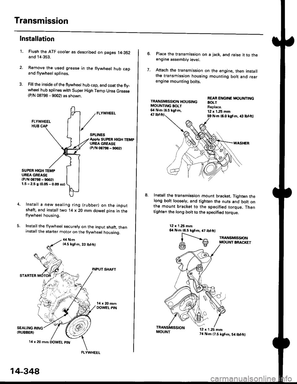
Installation
Flush the ATF cooler as described on pages 14-352and 14-353.
Remove the used grease in the flywheel hub caDand flywheel splines.
Fill the inside of the flywheel hub cap, and coat the fly-wheel hub splines with Super High Temp Urea Grease(P/N 08798 - 9002) as shown.
L
SEALING RING{RUEBER)
SPLINESApply SUPEB HlcH TEMPUREA GREASElPlN 08798 - 90O2t
SUPER HIGH TEMPUREA GREASE(P/N 08798 - !)00211.5-2.5 g 10.05-0.t9 oz)
Install a new sealing ring (rubber) on the inoutshaft, and install two '14 x 20 mm dowel Dins in theflywheel housing.
Install the flywheel securely on the input shaft, theninstallthe starter motor on the flywheel housing.
4,1Nmla.5 kgt.m, 33 tbt.ft)
INPUT SHAFT
STARTER
l4 x 20 mm DOWEL ptN
.4;i "lrj
,i rr,"r., ., a
14-348
FLYWHEEL
MOUI{T74 N.m (7.5 tstm,5a tbtftt
6. Place the transmission on s jack, and raise it to theengine assembly level.
7. Anach the transmission on the engine, then installthe transmission housing mounting bolt and rearengine mounting bolts.
TRANSMISSION HOUSINGMOUNTING BOIT6,1 N.m 16.5 kgl.m,47 tbtttl59 Nrn {6.0 kgl.m. ,€ lbt ftl
WASHER
lnstall the transmission mount bracket. Tighten thelong bolt loosely, and tighten the nuts and bott onthe mount bracket to the specified torque. Thentighten the long bolt to the specified torque.
REAR ENGINE MOUNTINGBOLTReplace.12 x 1.25 mm
12x 1.25 mn6,r N'm 16.5 kgtm,47 tbtftl
l-".--..-,^
G\V
TRANSMISSONMOUNT BRACKET
12 x 1.25 mn