1996 HONDA CIVIC Crankshaft bolt
[x] Cancel search: Crankshaft boltPage 204 of 2189

Flywheel and Drive Plate
Replacement
Manual Transmission:
816A2 engine:
Remove the eight flywheel bolts, then separate the fly-
wheel from the crankshaft flange. After installation'
tiohten the bolts in the sequence shown
RING GEAR HOLDER "-i
OTLAB PVOOlOO
D16Y5, D16Y7, D16Y8 engines:
Remove the six flywheel bolts, then separate the flywheel
from the crankshaft flange. After installation, tighten the
bolts in a crisscross Pattern.
RING GEABInspect ring gear
teeth lor wear or
damage.
RING GEARInspect ring gear
teeth lor wear orteetn lor wea( or /danase. ,///.'
12 x 1.0 mm103 N.m(10.5 kgf.m, 76 lbf.tt)
12 x 1.o mm1 18 N,m(12.0 kgI.m, 87 lbf.ftl
L
rurS;u'.\
$..3s'
Automatic Transmission:
Remove the six drive plate bolts, then separate the drive
olate from the crankshaft flange. Atter installation, tighten
the bolts in a crisscross Pattern.
t7.5 kgl.m, 54 lbl'ltl
12 x 1.0 mm74 N.m
7-7
Page 206 of 2189
Main Bearings
4.
Glearance
1.To check main bearing-to-journal oil clearance.
remove the main caps and bearing halves.
Clean each main journal and bearing half with a
clean shop towel.
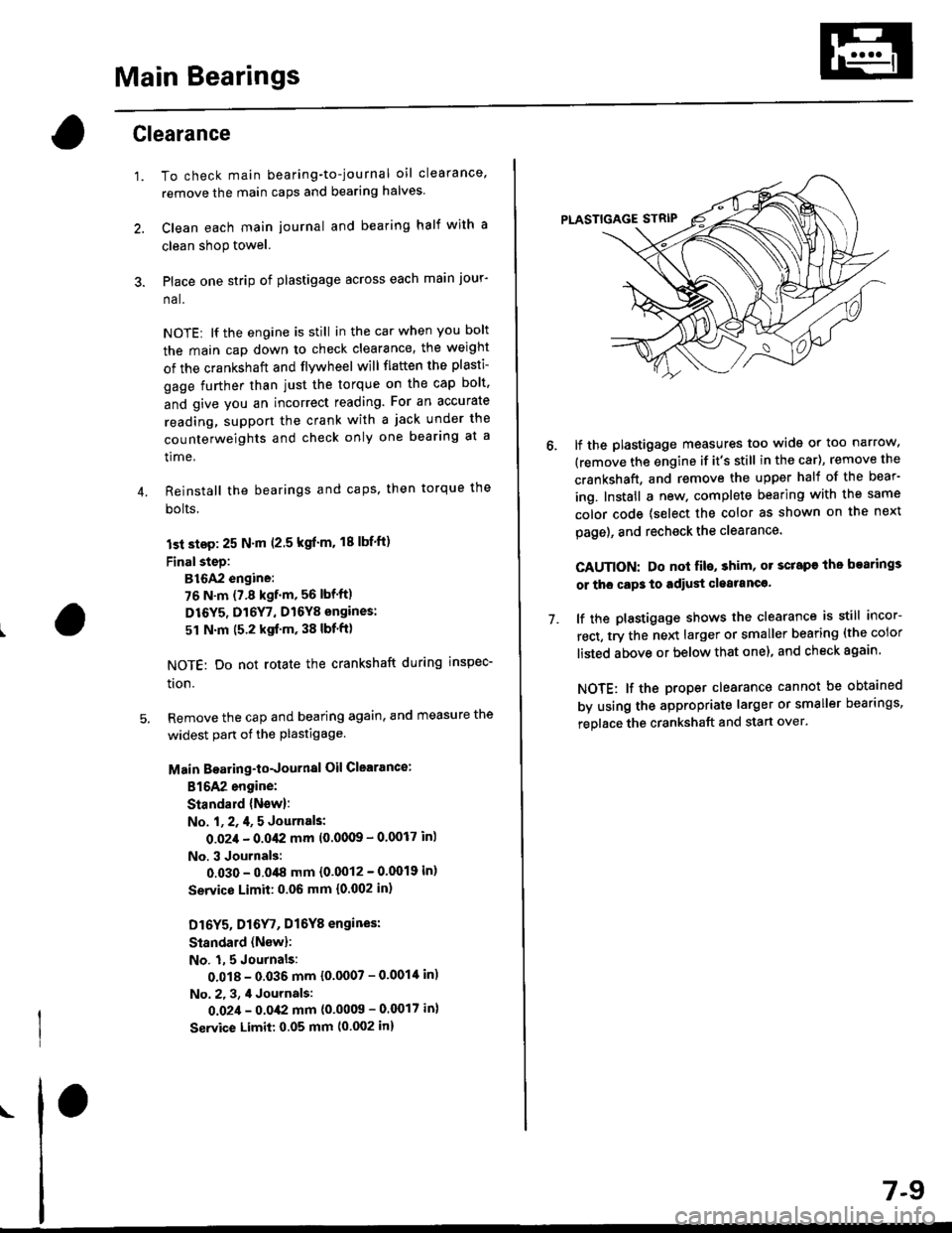
Place one strip of plastigage across each main jour-
na l.
NOTE: lf the engine is still in the car when you bolt
the main cap down to check clearance, the weight
of the crankshaft and flvwheel will flaften the plasti-
gage further than just the torque on the cap bolt.
and give you an incorrect reading. For an accurate
reading, support the crank with a jack under the
counterweights and check only one bearing at a
time,
Reinstall the bearings and caps, then torque the
bolts.
lst step: 25 N'm (2.5 kgl'm. 18 lbf'ft)
FinalsteD:
B16A2 engine:
76 N.m (7.8 kgf.m, 56 lbf'ft)
D16Y5, Dl6Y7, D16Y8 engines:
51 N.m (5.2 kgf'm, 38 lbf'ft)
NOTE: Do not rotate the crankshaft during inspec-
tron.
Remove the cap and bearing again, and measure the
widest part ot the plastigage.
Main Boaring-toJournal Oil Clearance:
816A2 engine:
Standald {New}:
No. l, 2, 4, 5 Journals:
O.O2,l - 0.042 mm 10'00(B - 0.0017 in)
No. 3 Journals:
0.030 - 0.048 mm {0'0012 - 0'0019 in)
Servico Limit: 0.06 mm {0.002 in,
Dl6Y5, Dl6
r, Dl6Y8 engines:
Standard (Nsw):
No. 1,5 Journals:
0.018 - 0.035 mm {0.0007 - 0'001'[ in)
No. 2. 3, 4 Journals:
0.02,1 - 0.0,(2 mm {0'0009 - 0.0017 in}
Service Limit: 0.05 mm (0.002 in)
\
7-9
7.
lf the plastigage measures too wide or too narrow,
(remove the engine if it's still in the car), remove the
crankshaft, and remove the upper half of the bear-
ing. Install a new. complete bearing with the same
color code {select the color as shown on the next
page), and rechsck the clearance.
CAUTION: Do nol fil€, shim, or scrape the bearings
or tho cap3 to adiust cleatanc€.
lf the plastigage shows the clearance is still incor-
rect, try the next larger or smaller bearing (the color
listed above or below that one), and check again
NOTE: lf the proper clearance cannot be obtained
by using the appropriate larger or smaller bearings,
replace the crankshaft and start over.
Page 210 of 2189
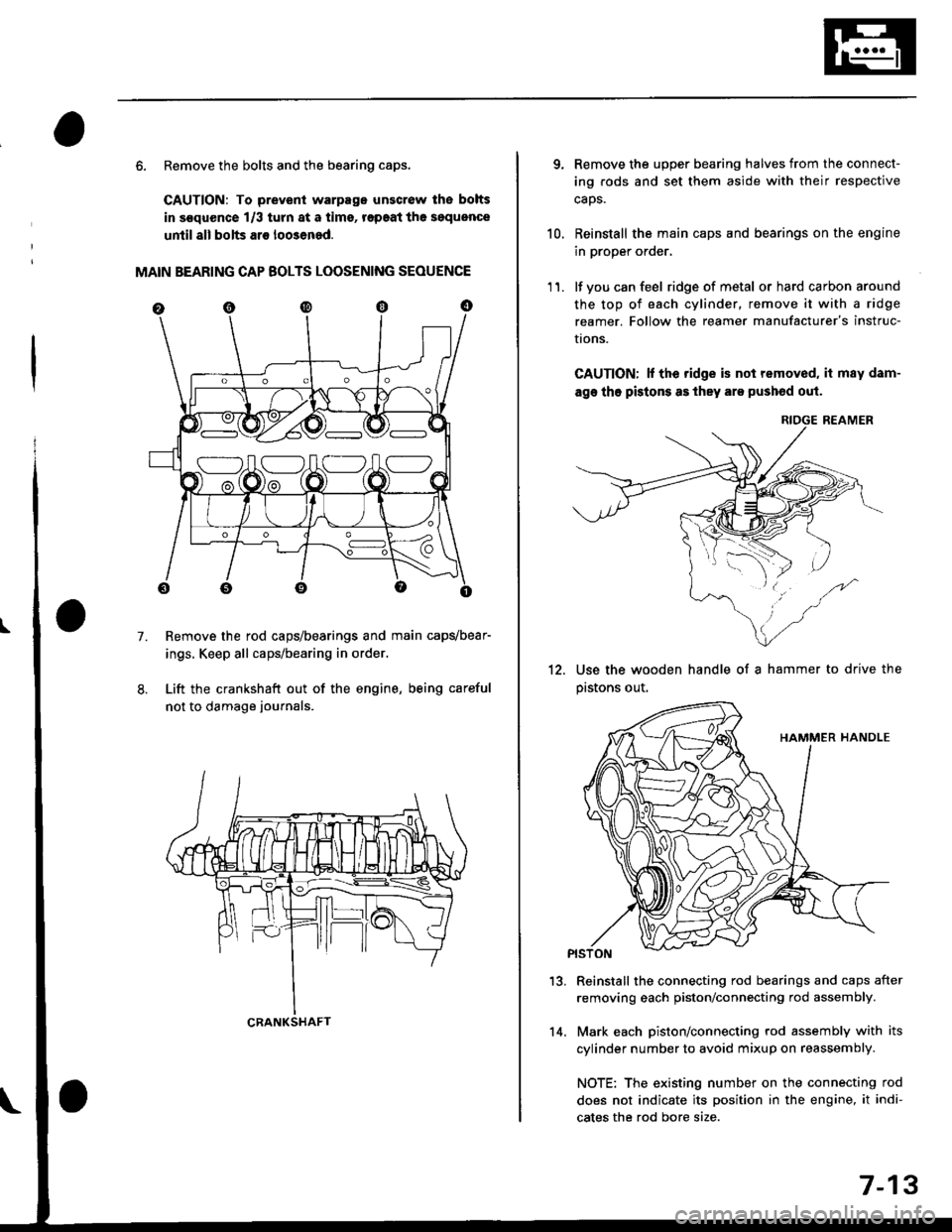
6. Remove the bolts and the bearing caps.
CAUTION: To prevenl warpago unscrow lhe bolts
in s€quence 1/3 turn at a tims, r€paat the soquence
until all bolts ar€ loo3ened.
MAIN BEARING CAP BOLTS LOOSENING SEOUENCE
Remove the rod caps/bearings and main capvbear-
ings. Keep all caps/bearing in order.
Lift the crankshaft out of the engine, being careful
not to damage journals.
7.
S:_]ILOJLOAO
CRANKSHAFT14.
7-13
qRemove the upper bearing halves from the connect-
ing rods and set them aside with their respective
caos.
Reinstall the main caps and bearings on the engine
in proper order,
lf you can feel ridge of metal or hard carbon around
the top of each cylinder, remove it with a ridge
reamer. Follow the reamer manufacturer's instruc-
I|ons.
CAUTION; lf the ridge is not removed, it may dam-
age tho pistons as they are pushod out.
RIOGE REAMER
10.
11.
12.Use the wooden handle of a hammer to drive the
pastons out.
13.Reinstall the connecting rod bearings and caps after
removing each piston/connecting rod assembly.
Mark each piston/connecting rod assembly with its
cylinder number to avoid mixup on reassembly.
NOTE: The existing number on the connecting rod
does not indicate its position in the engine, it indi-
cates the rod bore size.
Page 220 of 2189
PistonsGrankshaft
lnstallation
Before installing the pistons, apply a coat of
engine oil to the ring grooves and cylinder
bores.
lf the crankshaft is already installed:
. Set the crankshaft to BDC for each cylinder.
. Remove the connecting rod caps, and slip short
sections of rubber hose over the threaded ends
of the connecting rod bolts.
. lnstall the ring compressor. check that the bear-
ing is securely in place, then position the piston
in the cylinder, and tap it in using the wooden
handle of a hammer.
o Stop after the ring compressor pops free, and
check the connecting rod-to-crank journal align-
ment before pushing the piston into place
. Apply engine oil to the bolt threads. Install the
rod caps with bearings, and torque the nuts to:
815A2 engine:
40 N.m {,1.1 kgf.m, 30 lbf'ft|
D16Y5, D16Y7, D16Y8 engines:
31 N.m (3.2 kgf'm,23 lbf'ft)
lf the crankshaft is not installed:
. Remove the rod caps and bearings, install the ring
compressor, then position the piston in the cylin-
der, and tap it in using the wooden handle of a
hammer.
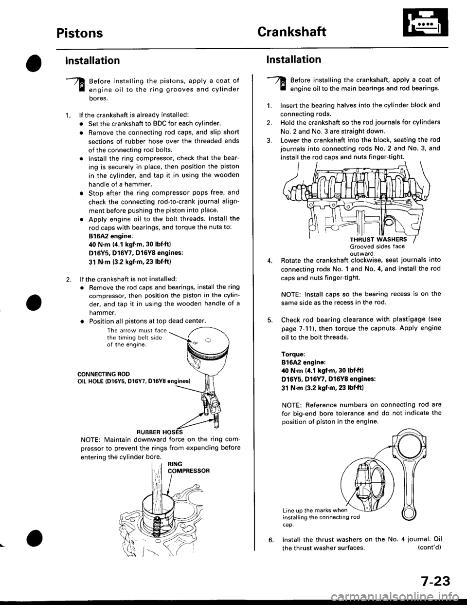
. Position all Distons at top dead center.
1.
2.
The arrcw must facethe taming belt sideof the engine.
CONNECTING ROOOIL HOLE lD16Y5, D16Y7, D16YB ongines)
NOTE: Maintain downward force on the ring com-
pressor to prevent the rings from expanding before
entering the cylinder bore.
RUBBER
,lll
lnstallation
Before installing the crankshaft, apply a coat of
engine oil to the main bearings and rod bearings.
Insert the bearing halves into the cylinder block and
connecting rods.
Hold the crankshaft so the rod journals for cylinders
No.2 and No. 3 are straight down.
Lower the crankshaft into the block, seating the rod
journals into connecting rods No. 2 and No. 3, and
install the rod caps and nuts finger-tight.
1.
2.
3.
5.
Grooved sides faceoulward.Botate the crankshaft clockwise, seat journals into
connecting rods No, 1 and No.4, and install the rod
caps and nuts finger-tight.
NOTE: Install caps so the bearing recess is on the
same side as the recess in the rod.
Check rod bearing clearance with plastigage (see
page 7-11), then torque the capnuts. Apply engine
oil to the bolt threads.
Torque:
816A2 sngine:/l{, N.m {a.l kgf.m, 30 lbf'ftl
D16Y5, D16Y7, Dl6Y8 engines:
31 N.m (3.2 kgf.m, 23 lbf'ft|
NOTE: Reference numbers on connecting rod are
for big-end bore tolerance and do not indicate the
position of piston in the engine.
Line up the marks wheninstalling the connectrng rod
cap.
6. Install the thrust washers on the No. 4 journal. Oil(cont'd)
7-23
the thrust washer surfaces,
Page 221 of 2189
Crankshaft
Installation (cont'd)
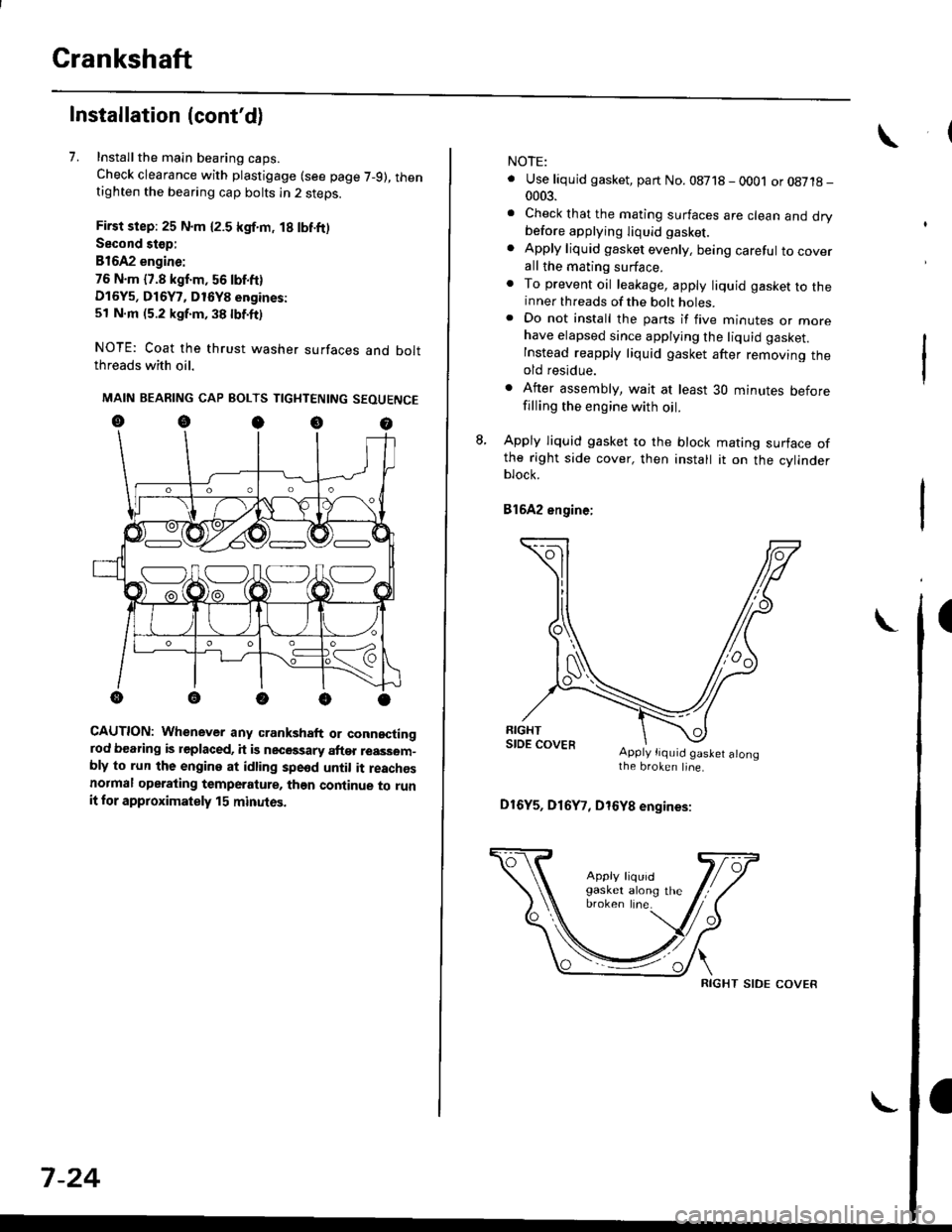
7. Installthe main bearing caps.
Check clearance with plastigage (see page 7-9), thentighten the bearing cap bolts in 2 steps.
First step: 25 N.m {2.5 kgf.m, 18 lbf.ft)
Second stop:
B1642 engine:
76 N.m {7.8 kgf.m, 56 lbf.ft)
D16Y5, D16Y7, D16Y8 engines:
51 N.m (5.2 kgf.m, 38 lbf.ft)
NOTE: Coat the thrust washer surfaces and boltthreads with oil.
MAIN BEARING CAP BOLTS TIGHTENING SEOUENCE
oocoo
CAUTION: Whenever any crankshaft or connectingrod bearing is replaced, it is necGssary after reassom-bly to run the engine at idling spe6d until it reachesnormal operating temperature, than continue to runit for approximately 15 minutos.
:V fr\-/.---\-/.-
7-24
NOTE:
. Use liquid gasket, part No. 08718 - 0001 or08718-0003.
. Check that the mating surfaces are clean and drybefore apptying liquid gasket.
. Apply liquid gasket evenly, being careful to coverall the mating surface.. To prevent oil leakage, apply liquid gasket to theinner threads of the bolt holes.. Do not install the parts if five minutes or morehave elapsed since applying the liquid gasket.
Instead reapply liquid gasket after removing theold residue.
. After assembly, wait at least 30 minutes beforefilling the engine with oil.
L Apply liquid gasket to the block mating surface ofthe right side cover, then install it on the cylinderblock.
Bl6A2 engine;
Apply tiquid gaslet alongthe broken line.
D16Y5, D16Y7, D16Y8 engines:
RIGHT SIDE COVER
Page 454 of 2189
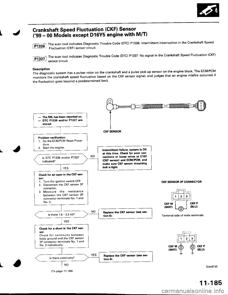
tCrankshaft Speed Fluctuation (CKF) Sensor -
('99 - 00 Mociels except D16Y5 engine with M/T)
The scan tool indicates Diagnostic Trouble code (DTC) P1336: Intermittent interruption in the crankshaft speed
Fluctuation (CKF) sensor circuit
The scan tool indicates Diagnostic Trouble Code (DTC) P1337: No signal in the Crankshaft Speed Fluctuation (CKF)
sensor circuat,
Description
Thediagnosticsystemhasapulserrotoronthecrankshaftandapu|sepick-upsensorontheengineb|ock.TheEcM/PcM
monitors the crankshaft speed fluctuation based on the cKF sensor signal. and judges that an engine misfire occurred if
the fluctuation goes beyond a predetermined limit'
I
Ftu6l
tF13g7l
CKF SENSOR 3P CONNECTOR
r--r t|-.r-r'--]llll l2l3ll.l---'.-T_
CKFM I I CKFP
twHTl |/Ai i lBlul--\9-
Terminal side oI male terminals
CKF M(WHT)CKF P(BLU)
t(cont'd)
1 1-185
- The MIL has b€on reportad on.- DTC P1336 and/or P1337 are
stored.
Problem verification:1. Do the ECM/PCM Reset Proce'
dure.2. Start the enginelntermittcnt failuro, sydcm is OK
ai this time. Check lot Poor con_
noctions or loo3e wiros at C102
ICKF s€nsor) and ECM/FCM, and
make suro CKF sansor mounting
bolt b tight.
Check tor an open in the CKF sen_
1. Turn the ignition switch OFF
2. Disconnect the CKF sensor 3P
3. Measure the resistance
between the CKF sensor 3P
connector terminals No. 1 and
No.3.
ls there 1.6 3.2 kO?
Check for a short in ihe CKF sen_
sot:Check for continuity betweenbody ground and the CKF sensor
3P connector terminals No 1 and
No.3 individuallY.
(To page 11-186)
Page 576 of 2189
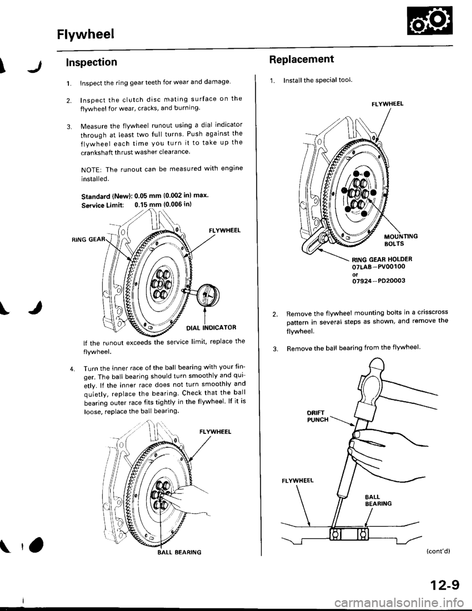
Flywheel
\Inspection
1.
2.
3.
Inspect the ring gear teeth for wear and damage
Inspect the clutch disc mating surface on the
flywheel for wear, cracks, and burning.
Measure the flywheel runout using a dial indicator
through at least two full turns Push against the
flywheel each time you turn it to take up the
crankshaft thrust washer clearance.
NOTE: The runout can be measured with engine
installed.
Standard (New): 0.05 mm (0.002 inl max.
Service Limit: 0.15 mm {0.006 in)
FLYWHEEL
OIAL INOICATOR
FLYWHEEL
lf the runout exceeds the service limit. replace the
flywheel.
Turn the inner race o{ the ball bearing with your tin-
ger. The ball bearing should turn smoothly and qui
etly. lf the inner race does not turn smoothly and
quietly, replace the bearing. Check that the ball
bearing outer race fits tightly in the flywheel. lf it is
loose. replace the ball bearing
IJ
4.
BALL BEARING tO
Replacement
1. Installthe special tool.
MOUNTINGBOLTS
RITIG GEAR HOLDER
oTLAB-PV00100oto7924-PD20003
2.Remove the flywheel mounting bolts in a crisscross
pattern in several steps as shown, and remove the
flywheel,
Remove the ball bearing from the flywheel
(cont'dl
12-9
FLYWHEEL
t\
m\J
Page 577 of 2189

FlywheelClutch Disc, Pressure Plate
Replacement (cont'dl
4. Drive the new ball bearing into the flywheel using
the special tools as shown.
DRIVER07749-0010000
ATTACHMENT,32x35mm07746-OOIOTOO
FLYWHEEL
BEARING
Align the hole in the flywheel with the crankshaft
dowel pin and install the flywheel. Install the
mounting bolts finger-ti9ht.
Install special tool, then torque the flywheel mount-
ing bolts in a crisscross pattern in several steps as
snown.
5.
6.
MOUNTING BOLTS118 N.m (12.0 kgl.m,87 tbf.ft)
RING GEAR HOLDER07LAB-PV00100ol07924 -PO20003
WVa// ,
12-10
Installation
1. Install the special tool.
Y
07936-3710r00
{P/N 08798-90021
RING GEAR HOLDER07LAB-PVOO100ot07924-PD20003
CLUTCH ALIGNMENT SHAFTOTJAF_PM7012A
2.
3.
Installthe clutch disc using the special tools.
Install the pressure plate.
RING GEAR HOLDERoTLAB PV00'l OO
07924 PD20003
OTJAF_PM70124HANOLE07936-3710100
CLUTCH DISC