Page 397 of 2189

PGM-FI System
Engine Coolant Temperature (ECTI Sensor
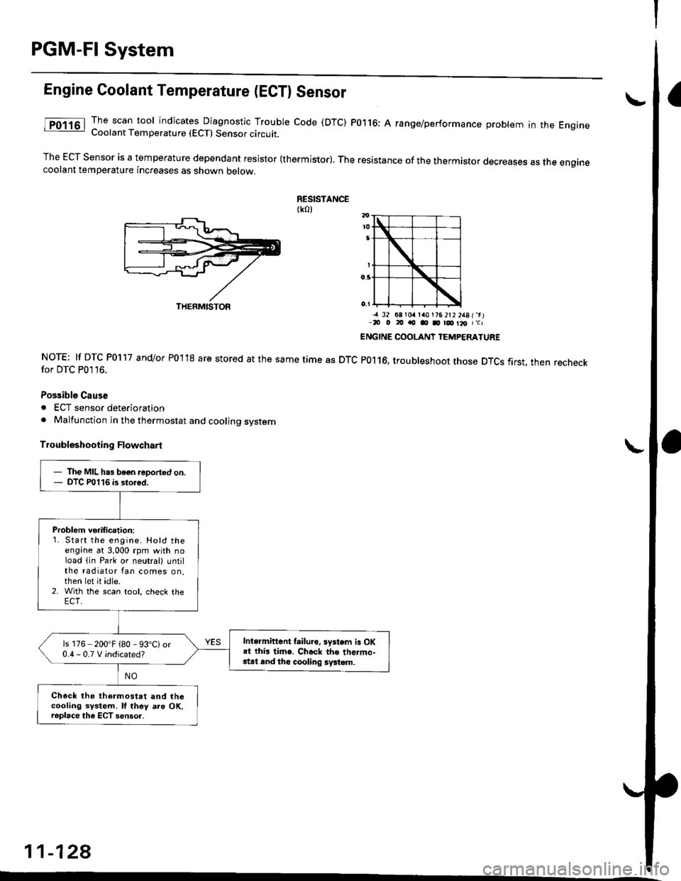
The scan tool indicates Diagnostic Trouble code (DTC) P0116; A range/performance problem in the EngrneCoolant Temperature (ECT) Sensor circuit.
The ECT Sensor is a temperature dependant resistor (thermistor). The resistance of the thermistor decreases as the enginecoolant temperature increases as shown oetow.
RESISTANCE(ko)
NOTE: lf DTC P0117 and/or P01'18 are stored at the same time as DTCfor DTC P0116.
Possible Cause
. ECT sensor deterioration. Malfunction in the thermostat and cooling system
Troubleshooting Flowchart
-a 32 68 r0a la0l?6 2t2 2481'rr-20 o 20 ao o D r@ Il, r'c)
ENGINE COOLANT IEMPERATURE
P0116, troubleshoot those DTCS first. then recheck
11-128
THERMISTOR
- The MIL has bogn reported on.- DTC P0116 is stored.
Problem verification:1. Start the engine. Hotd theengine at 3,000 rpm with noload (in Park or neutral) untilthe radiator fan comes on,then let it idle.2. With the scan tool, check the
Intermiftent lailure. system is OKai thi. time. Ch.ck the thc.mo-stat 6nd thc cooling system.
is 176 200'F {80 - 93'C)or0.0-0.TVindicated?
Check the thermostat and thecooling system. ll they als OK,raplace the ECT sensor.
Page 398 of 2189

|.
'f
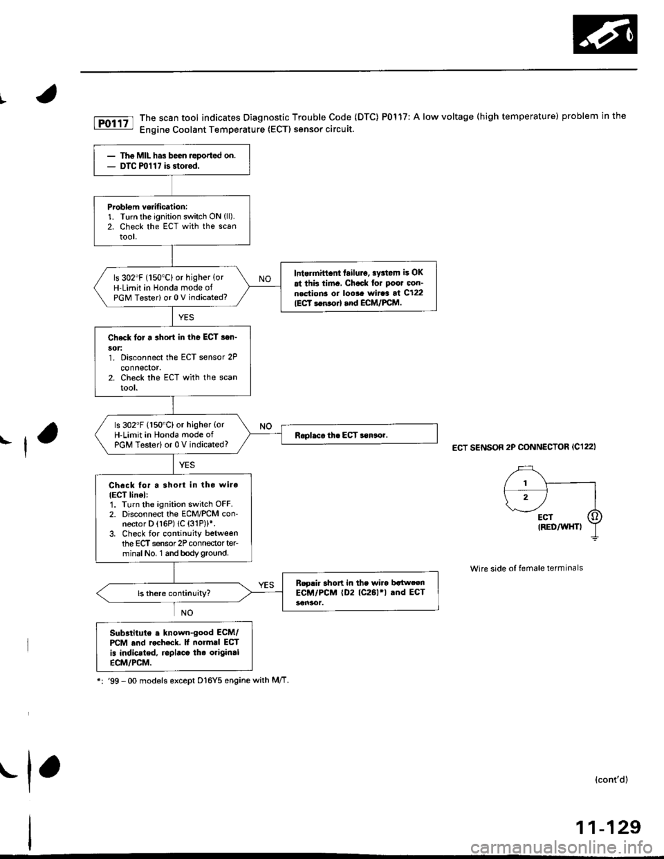
fD;r.tt The scan tool indicates Diagnostic Trouble Code (DTC) P0117: A low voltage (high temperature) problem in the|jg Engine Coolant Temperature (ECTI sensor circuit.
ECT SENSOR 2P CONNECTOR (C122I
Wire side of female terminals
Substitute . lnown-good ECM/PCM .nd rocheck. It normrl ECT
is indic.ted, replaco the original
ECM/PCM,
*:'99 -Oo models except D16Y5 enginewith M/T
(cont'd)
11-129
The MIL has been ,eported on.DTC ml 1 7 is storod.
Problom vorification:1. Turn the ignition switch ON (ll).
2. Check the ECT with the scantool.
Intermittont failulo, sy3tom it OK
at thk tim., Chock for Poor oon-n.ctions or loo!. wiraa at C122IECT 3en orl and ECM/FCM.
ls 302"F (150"C) or higher {orH-Limit in Honda mode ofPGM Tester) or 0 V indicated?
Check toJ a short in the ECT s.n-5('t:1. Disconnect the ECT sensor 2P
connector.2. Check the ECT with the scanrool.
ls 302"F (150"C) or higher {orH-Limit in Hond6 mode ofPGM Testerl or 0 V indicated?
Check for a 3hort in tho wiro
IECT linel:1. Turn the ignition switch OFF.2. Disconnect the ECM/PCM con-nector D (16P) (C {31P))*.3. Check for continuity betweenthe ECT sensor 2P conneclor ter-minalNo, 1 and bodyground.
B.gair short in the wiro bltweenECM/PCM (D2 (C261'l .nd ECT
.1,
Page 399 of 2189

PGM-FI System
Engine Coolant Temperature (ECT) Sensor
('96 - 98 Models,'99 - 00 D16YS engane with M/T) (cont'd)
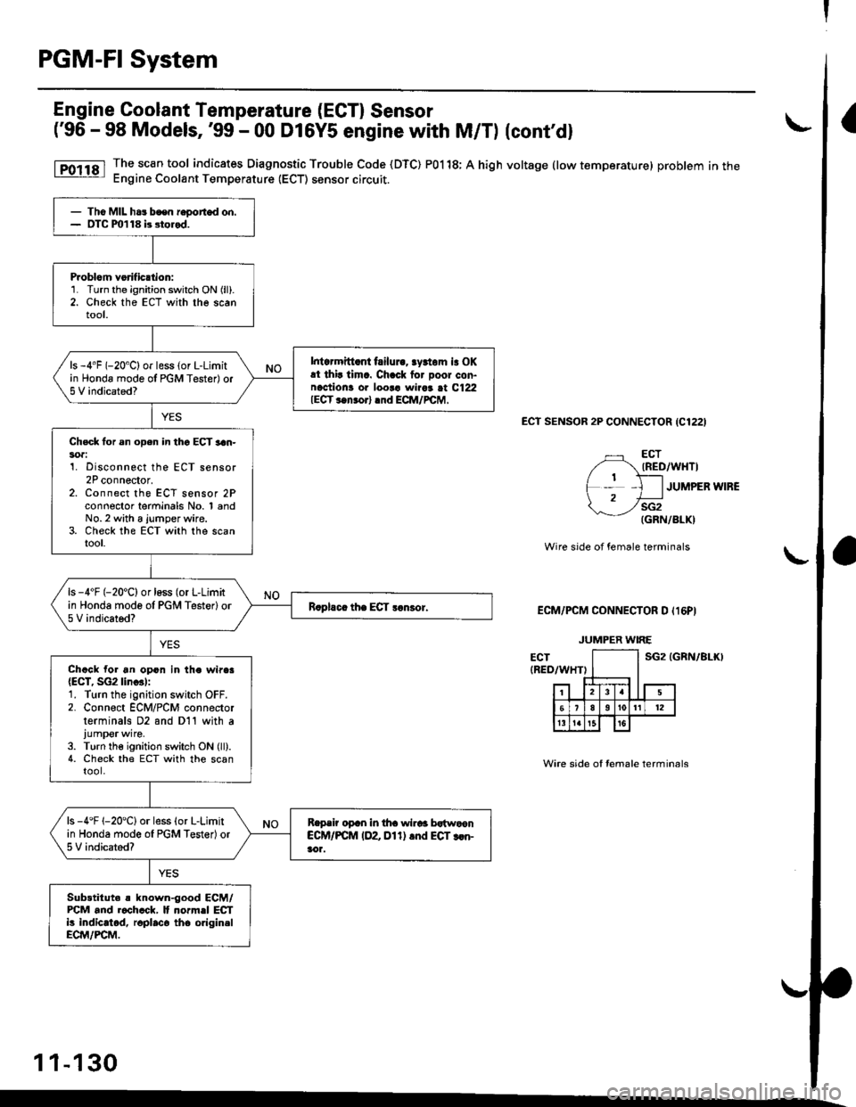
The sc€n tool indicates Diagnostic Trouble Code (DTC) P0118; A high voltage (low temperature) problem in theEngine Coolant Temperature (ECT) sensor circuit.
ECt SENSOR 2P CONNECTOR {C1221
ECTIRED/WHTI
JUMPER WIRE
sG2(GRN/BLK)
Wire side of female terminals
ECM/PCM CONNECTOR D Il6PI
sG2 tGRN/81r0
Wire side of Iemale terminals
- Tho MIL ha3 bcen r€oorted on.- OTC m118 b stored.
Problom vorificttion:1. Turn the ignition switch ON (ll).
2. Check the ECT with the scantool.
Intcrmitt.nt failui.. rydom is OKat thir timc. Chack for Door con-naction! or loor! wiaar at C122IECT ..n.orl .nd ECM/rcM,
ls -4"F (-20'C) or less (or L-Limitin Honda mode ol PGM Tester) or5 V indicated?
Chsck lor sn open in thc ECT 3an-soa:1. Disconnect the ECT sensor2P connector.z. Lonnecr rne ELt sensor zFconnector terminals No. 1 andNo.2 with a jumper wire.3. Check the ECT with the scantool.
ls -4'F (-20'C) or loss (or L-Limitin Honda mode ol PGM Testerlor5 V indicated?
Chack for an opon in the wire.{ECT, SG2lin..l:1. Turn the ignition switch OFF.2. Connect ECM/PCM connectorterminals D2 and D11 with ajump€rwire.
3. Turn the ignition switch ON (ll).4. Check the ECT with the scantool.
ls -4'F 1-20'Clor less (o. L-Limitin Honda mode ol PGM Tester)or5 V indicated?
Reprir oprn in tha wirar bstwoonCCM/PCM IDZ Dl1) .nd EGT rcn-aor.
Sub3titut. s known-good ECM/FCM and r.chcck, It normel ECTi! indicatod, roplaco tho origin.lECM/PCM.
JUMPER WIRE
1 1-130
Page 400 of 2189

PGM-FI System
t
I
Engine Coolant Temperature (ECT) Sensor
('99 - 00 Models except Dl6Y5 engine with M/Tl
The scan tool indicates Diagnostic Trouble Code (DTC) P0118: A high voltage (low temperature) problem in the
Engine Coolant Temperature (ECT) sensor circuit.
ECT SENSOR 2P CONNECTOR {C122)
ECT(RED/Wr{T)
JUMPER IVIRE
sG2{GRN/BLK)
wire side of female terminals
ECM/PCM CONNECTOB C 131PI
The MIL has been reported on,
oTC P0118 is stored.
Problem verilication:1. Turn the ignition switch ON (ll).
2. Check the ECT with the scan
tool.
lntormittent failuro, systom is OK
at thb timo. Check lor poor con'nections or 10036 wiraa at C122
{ECT ssnsorl and ECM/rcM.
ls -4'F (-20"C) or less lor L-Limit
in Honda mode o{ PGM Tester) or
5 V indicated?
Check for an open in the Efi sen'
sori1. Disconnect the ECT sensor 2P
connector,2. Connect the ECT sensor 2P
connector terminals No, 1 andNo. 2 with a jumper wire.3. Check the ECT with the scantool.
ls -4"F 1-20"C) or less (or L-Limit
in Honda mode of PGM Tester) or
5 V indicated?
Check for sn open in the wires
IECT. SG2 linesl:1. Turn the ignition switch OFF.2. Connect ECM/PCM connectorterminals C18 and C26 with ajumper wire.3. Turn the ignition switch ON (ll).
4. Check the ECT with lhe scantooi.
Rspair opon in th6 wiros bstwoon
ECM/PCM (Cl8, C26l and ECT
3ensot.
ls -4'F {-20"C) or less (or L-Limit
in Honda mode of PGN4 Tester) or
5 V indicated?
Substitute 6 known-good ECM/PCM and recheck. l{ no.mal EcT
is indicatod, .eplace the originalECM/PCM.
JUMPER WIRE
Wire side of female terminals
11-131
Page 461 of 2189

ldle Control System
ldle ControlSystem
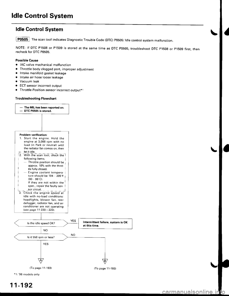
lF0505 l Th" """n tool indicates Diagnostic Trouble Code (DTC) PO5O5: tdte controt system malfunction.
NOTE: lf DTC P1508 or P1509 is stored at the same time as DTC P0505, troubleshoot DTC p1508 or p1bog first. thenrecheck for DTC P0505.
Possible Cause
. IAC valve mechanical malfunction
. Throttle body clogged pon, improper adjustment. Intake manifold gasket leakage
. Intake air hose loose leakage
. Vacu um leak
. ECT sensor incorrect output
. Throttle Position sensor incorrect output*r
Troubleshooting Flowchart
The MIL has been reoorted on.DTC P0505 is stored.
Problem verification:1. Start the engine. Hold theeng;ne at 3,000 rpm with noload (jn Park or neutral) untilthe radiator fan comes on, then*r let it idle.t2. with rhe scan toot, ct'eit Ge l
Throttle position should beapprox. 10% with the throttle fully closed.E ngine coolant tempera-ture should be 194 205'F(90 96.Ci.lf they are not within thespec., repair the faulty sen
L._ _9oI9[cr]41 l3. Chec& the engine speed atidle with no-load cond;tionsiheadlights, blower fan, reardefogger, radiator fan, and airconditioner are not operating\see page l1-22O - 223).
Intermittent tailure, system is OKat this time.ls the idle speed OK?
ls it 550 rpm or less?
(To page 11,193)
*1r'96 models only
11-192
(To page ll-193)
Page 512 of 2189
Intake Air System
\JSystem DescriPtion
The system supp|ies air for a|| engine needs' |t consists of the intake air pipe' Air C|eaner (ACL}, intake air duct, Thrott|e
Body (TB), ldle Air control (lAc) valve and intake manifold. A resonator in the intake air pipe provides additional silencing
as air is drawn into the system.
D16Y5, D16Y8, 816A2 engine {M/Tl
YEL/ - From PGM-FIaLK - MA|N RELAY
BLK/BLU
-- ORN
INTAKEAIRDUCT
IROTARYIIAC VALVE
Iaru
ENGINECOOLANT
BLK/
INTAKEAIR DUCT
I
D16Y5 engine (CVT), D16Y8 engine (A/T)' f'ttlxr ,tla"tpoto
D16Y7 engine:
{ROTARY)IAC VALVE
VARIOUSSENSORS
INTAKEAIRPIPE
tr
RESONATOR
!r,
IAC VALVE
BLK
11-243
Page 516 of 2189

IThrottle BodY
Description
The throttle bodY is either a single-barrel side-draft type
(D16Y5, D16Y8, 816A2 engine) or a down-draft type
(D16Y/ engine). The lower portion ot the throttle valve is
heated by engine coolant from the cylinder head' The
idle adjusting screw which regulates the bypass air is
located on the top of the throttle body
THROTTLEPOS|T|ON lTPlSENSOR
IDLE AD.'USTINGSCREW
t
In3pection
1. Check that the throttle cable operates smoothly
without binding or sticking.
lf there are any abnormalities, check for:
. Excessive wear or play in the throttle valve shaft'
. StickY or binding throttle lever at the fully closed
Position.. Clearance between throttle stop screw and throt-
tle lever at the fully closed position'
D16Y5, Dl6Y8 engine:
THROTTLE STOP SCREW
{Do not adjust.)
Dl6Y7 ongine:
816A2 engins:
THROTTLE LINK
STOP SCREW
THROTTTE STOP SCREW(Do not adjust.)
Replace the throftle body if thsre is excessive play in the
throttle valve shaft or iJ the shaft is binding or sticking'
(cont'd)
11-247
{Do not adjust.)
Page 553 of 2189

Emission Control System
Evaporative Emission (EVAPI Controls (cont'dl
1
EVAP CONTROLCANISTER VENT SHUTVALVE 2P CONNECTOR IC141}
lltrt+ rcl
o) (8LK/YErl
I
temale terminalsWire side ot
ECM/PCM CONNECTOR A (32PI
VSV ILT GRN/WHT}
'l'
Wiro side of lemaletgrminals
VACUUMPUMP/GAUGE,0 - 30 in.Hg4973X -
041 - XXXXX
(From page 1l-283)
{To page 1l-285}
Check the vacuum whon cold:1. Disconnect the vacuum hoseshown from the EVAP controlcanrster and connect a vacuumgauge to the hose,2. Start the engine and allow itto idle.NOTE: Engine coolant tem-perature must be below 154oF(68'C) or lVC switch OFF.3. Ouickly raise the engine speedto 3,000 rpm.
(From page l1-283)
Check for an open in tho wire(lGl line):1. Turn the ignition switch OFF.2. Disconnect the 2P connectorlrom the EVAP control canis-ter vent shut valve.3. Turn the ignition switch ON (ll).4. Measure voltage between theEVAP controlcanister vent shutvalve 2P connector terminalNo. 2 and body ground.
Repair open in the wire betwe€nthe EVAP control c.ni3tei ventshut valve and th6 No. 15 ALTER-NATOR SP SENSOR 17.5 Al fuse.
Cfisck tor an opon in the wire (VSVline):1. Turn the ignition switch OFF.2. Beconnect the 2P connectorto the EVAP control canistervent shut valve.3. Turn the ignition switch ON (ll).4. Measure voltage betweenECM/PCM connector termi-nals A29 and Al0.
Rep.ir open in the wire betwoonthe EVAP control canister ventshut valve and th€ ECM/PCMtA29t.
ls there battery voltage?
Replace th6 EVAP control canis-ter vent 3hut valve.
PGT (BLKI
:lI23l'ltl'l lelsl ro Ir I1213t6€lnltlr@/lzzl zs f il
25
11-284