Page 1581 of 2189

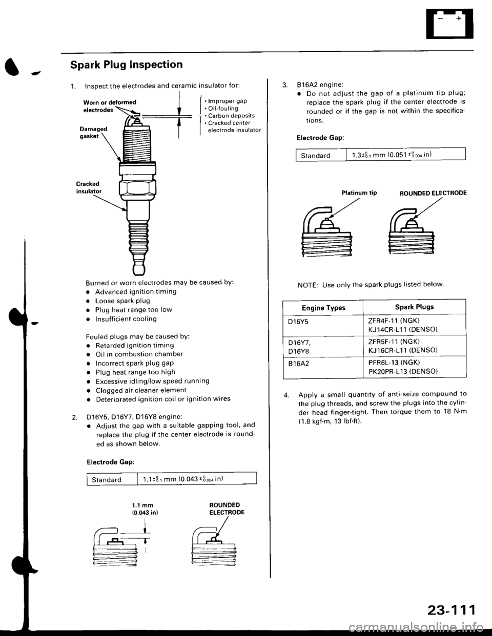
1. Inspect the electrodes and ceramic insulator for:
Spark Plug lnspection
Crackedinsulator
2.
[ . t.p,op", grp
| . Oil-fouling
i . Carbon deposits
| . Cracked center
I electrode insulator
Burned or worn electrodes may be causecl by:
. Advanced ignition timing
. Loose spark plug
. Plug heat range too low
. Insufficient cooling
Fouled plugs may be caused bY:
. Retarded ignition timang
. Oil in combustion chamber
. Incorrect spark plug gap
. Plug heat rangetoo high
. Excessive idling/low speed running
. Clogged air cleaner element
. Deteriorated ignition coil or ignition wares
D16Y5, D16Y7, D'16Y8 enginel
. Adjust the gap with a suitable gapping tool, and
replace the plug il the center electrode is round-
ed as shown below.
Electrode Gap:
1.1 mm
{o.{X:l in)ROUNDEDELECTRODE
Standard 1.1r8 ' mm (0.043i800oin)
Worn or detormed
1T
23-111
3. 816A2 engine:
. Do not adjust the gap of a platinum tip plug;
replace the spark plug il the center electrode is
rounded or it the gap is not within the specifica
tro ns.
Electlode Gap:
Standard 1.3181mm (0.051 !3oo" in)
flOUNDED ELECTROOE
',/
@_
:
Platinum tip
NOTE: Use only the spark plugs listed below
4. Apply a small quantity of anti seize compound to
the plug threads, and screw the plugs into the cylin
der head finger-tight. Then torque them to 18 N m
11.8 kgf.m, 13lbnft).
Engine TypesSpark Plugs
D16Y5ZFR4F 11 (NGK)
KJ14CR-111 (DENSOi
D16Y7,
D,I6Y8
ZFRSF-11 (NGK)
KJ16CR-111(DENSO)
81642PFR6L.13 (NGK)
PK2OPR.L13 (DENSO}
Page 1593 of 2189

JRotor Slip Ring Test
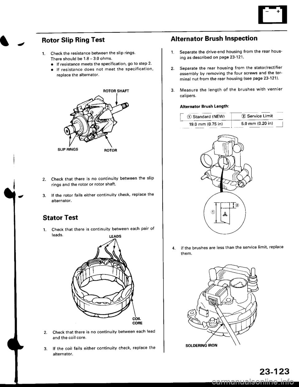
1. Check the resistance betlveen the slip rings
There should be 1 8 - 3 0 ohms
. lf resistance meets the specification, go to step 2.
. lf resistance does not meet the specification,
reolace the alternator'
SLIP BINGS
2. Check that there is no continuity between the slip
rings and the rotor or rotor shaft.
3. lf the rotor fails either continuity check, replace the
alternator.
Stator Test
'1. Check that there is continuity between each pair of
leads.
CORE
Check that there is no continuity between each lead
and the coil core.
lf the coil fails either continuity check, replace the
alternator.
ROTOR SHAFT
LEADS
1.
Alternator Brush InsPection
Separate the drive-end housing from the rear hous-
ing as described on page 23-121
Separate the rear housing from the stator/rectifier
assembly by removing the four screws and the ter-
minal nutfrom the rear housing {see page 23-121}
lvleasure the length of the brushes with vernrer
calrpers.
Alternator Brush Length:
O Standard {NEW} @ Service Limit
19.0 mm (0.75 in) 1 5.0 mm (0 20 in)
lf the brushes are less than the service limit, replace
them.
23-123
Page 1598 of 2189
Gauge Assembly
Component Location Index
SRS components are located in this area. Review the SRS component locations, precautions, and procedures in the SRS
section (24) before performing repairs or service.
6x1.0mm9.8 N.m 11.0 kgf.m,22lbt.lrl
VEHICLE SPEED SENSOR {VSS)Troubleshooting, page 23-1 40
GAUGE ASSEMBLYGau ge/lndicator/TerminalLocation Index, page 23-129Removal, page 23-135Bulb Location, page 23-136Disassembly, page 23 138
PARKING BRAKE SWITCH
FLUIO LEVEL SW]TCH
23-128
ENGINE OIL PR€SSURE SWITCH
Page 1606 of 2189
Gauge Assembly
Bulb Locations (With Tachometer)
GAUGE LIGHT II.' WI
SEAT BELTREMINDER LIGHT I1.4 WI
LOW FUELLIGHT 13 W)
RIGHT TURN SIGNALINDICATOR LIGHT I1.4 WI
A/T GEARGAUGE LIGHTS 13 W)
CI{ARGING SYSTEM LIGHT (1.,1W)
GAUGE I-IGHT {1,4 WI
LOW ENGINE OIL PRESSUREINDICATOR LIGHT (1,' W}
HIGH EEAMINDICATOR LIGHT(1.4 W)
GAUGE LIGHT l3.il Wl
MALFUNCTIONINDICATORLAMP {MIL}BULE (1.{ Wl
WASHER I.'C VELINDICATOR LIGHT{1.4 Wl (Canada)
LEFT TURN SIGNALINDICATOR LIGHT {1.4 WI
sRsTOB (1.4 Wl
{On the printed circuit board)INDICATOR (1.12 x 6l(On the printed
circuit board)
ABS |ND|CATOR (1.. Wl{On the printed circuit board)CRUISE or SHIFT-UP INDICATOR 11.12 11.{On the orinted circuit board)
23-136
Page 1607 of 2189
JBulb Locations {Without Tachometer)
TRUNK INDICATORLIGHT {1.i1W}
.4 Wl
CHARGING SYSTEM LIGHT 11,4 W}
LTGHT (1.4 W)GAUGE LIGHT
SEAT BELTREMINDER LIGHT (1.4 WI
LOW ENGINE OIL PRESSUBE
INDICATOB LIGHT (1.4 WI
LOW FUEL INDICATORLrGl{T (3 W)
RIGHT TURN SIGNALINOICATOR LIGHT
(1.1Wt
GAUGE LIGHTS {3 WI
WASHER LEVELINDICATOR LIGHT{1.4 W} lcanad.l
HIGH BEAMINDICATOR LIGHTMALFUNCTIONINDICATORLAMP (MIL)
BULB {1.4 WI
{1.ilW)
LEFT TURN SIGNALINDICATOR LIGHT {1.4 WI
A/T GEAR POSITIONINDICATOR (1.12 x 6)(On the printed
circuit board)
sRs TND|CATOR 11.4 W)
{On the Drinted circuit board}
aBs tNDtcAToR t1.4 W)(On the printed circuit board)(3.{ Wt
o/ o \7 o
23-137
Page 1612 of 2189

Fuel Gauge
Gauge/Sending Unit Test
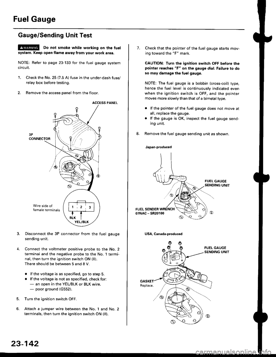
!@ Do not smoke while working on tho fuel
system. Keep open tlame away trom your wotk atea.
NOTE: Refer to page 23-133 for the fuel gauge system
circuit.
'1. Check the No. 25 (7.5 A) fuse in the under-dash fuse/
relay box before testing.
2. Remove the access panel from the floor.
ACCESS PANEL
Disconnect the 3P connector from the fuel gauge
sending unit.
Connect the voltmeter positive probe to the No. 2
terminal and the negative probe to the No. I termi-
nal, then turn the ignition switch ON (ll).
There should be between 5 and 8 V.
. lf the voltage is as specified, go to step 5.
. lf the voltage is not as specified. check for:- an open in the YEUBLK or BLK wire.- poor ground (G552).
Turn the ignition switch OFF.
Attach a jumper wire between the No. 1 and No. 2
terminals, then turn the ignition switch ON (ll).
)\
23-142
1.Check that the pointer of the fuel gauge starts mov-
ing toward the "F" mark.
CAUTION: Turn the ignition switch OFF before thepoinier reaches "F" on ihe gauge dial. Failure to do
so may damage the fuel gauge.
NOTE: The fuel gauge is a bobbin (cross-coil) type,
hence the fuel level is continuously indicated even
when the ignition switch is OFF, and the pointer
moves more slowly than that of a bimetaltype.
. lf the pointer of the fuel gauge does not move at
all, replace the gauge.
. lf the gauge is OK. inspect the fuel gauge send-
ing unit.
Remove the fuel gauge sending unit as shown.
Japan-produced
USA, Canada-produced
Page 1649 of 2189
High Mount Brake Light Replacement
Hatchback:
1. Loosen the two screws, then remove the high
mount brake light. Be careful not to damage the
hatch spoiler.
2. Remove the bulb socket from the light.
BULB SOCKET
l-
23-179
Coupe/sedan:
1. Remove the rear shelf (see section 20).
2 Remove the two screws, then remove the high
mount brake light from the rear shelf.
HIGH MOUNTBRAKE LIGHT
SCREWS
Page 1664 of 2189
Stereo Sound System
Window Antenna Wire Test
1. Wrap aluminum foil around the tip of the tester
probe as shown.
Touch one tester orobe to the window antenna ter-
minal near, and move the other tester probe along
the antenna wires to check that continuity exists.
WINDOW ANTENNA
23-194
OPEN
Window Antenna Wire Repair
NOTE: To make an effective repair, the broken section
must be no longer than one inch.
1. Lightly rub the area around the broken section with
fine steel wool, then clean it with alcohol.
2. Carefully mask above and below the broken portion
of the window antenna wire with cellophane tape.
CELLOPHANETAPE
Using a small brush, apply a heavy coat of silver
conductive paint extending about 1/8" on both
sides of the break, Allow 30 minutes to dry.
NOTE| Thoroughly mix the paint betore use.
Check for continuity in the repaired wire.
Apply a second coat of paint in the same way. Let it
dry three hours before removing the tape.