Page 198 of 2189

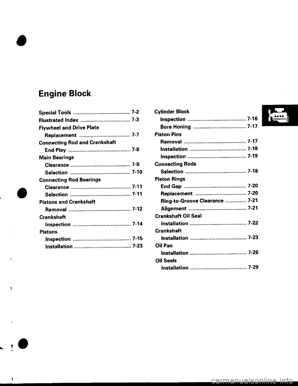
Engine Block
Speciaf Tools ..........." 7-2
lllustlated Index ...................."..'.......... 7-3
Flywheel and Drive Plate
Repf acement """'.' 7-7
Connecting Rod and Crankshaft
End Play ..........."....7-8
Main Bearings
Clearance ............... 7-9
Selection ................7-10
Connecting Rod Bearings
clearance ....'.......... 7-11
Selection ................ 7-11
Pistons and Crankshaft
Removaf ................. 7 -12
Crankshaft
Inspection ."".........7-14
Pistons
Inspection ......"'.....7-15
fnstaffation .............7-23
Cylinder Block
lnspec'tion ..............7-16
Bore Honing ..........7-17
Piston Pins
Removal ...,...........'.7-17
lnstallation .............7-18
Inspection .'............7-19
Connecting Rods
Selection ................7-18
Piston Rings
End Gap ..........".."' 7'2O
Repfacement .........7-2O
Ring-to-Groove Clearance ...........'.'. 7 -21
Afignment .......""'.. 7'21
Crankshaft Oil Seal
fnstaffation .............7-22
Crankshaft
fnstaffation ..-.-..'.".' 7'23
Oil Pan
lnstallation .............7-26
Oil Seals
fnstaffation ....""""' 7-29
r-f
Page 200 of 2189

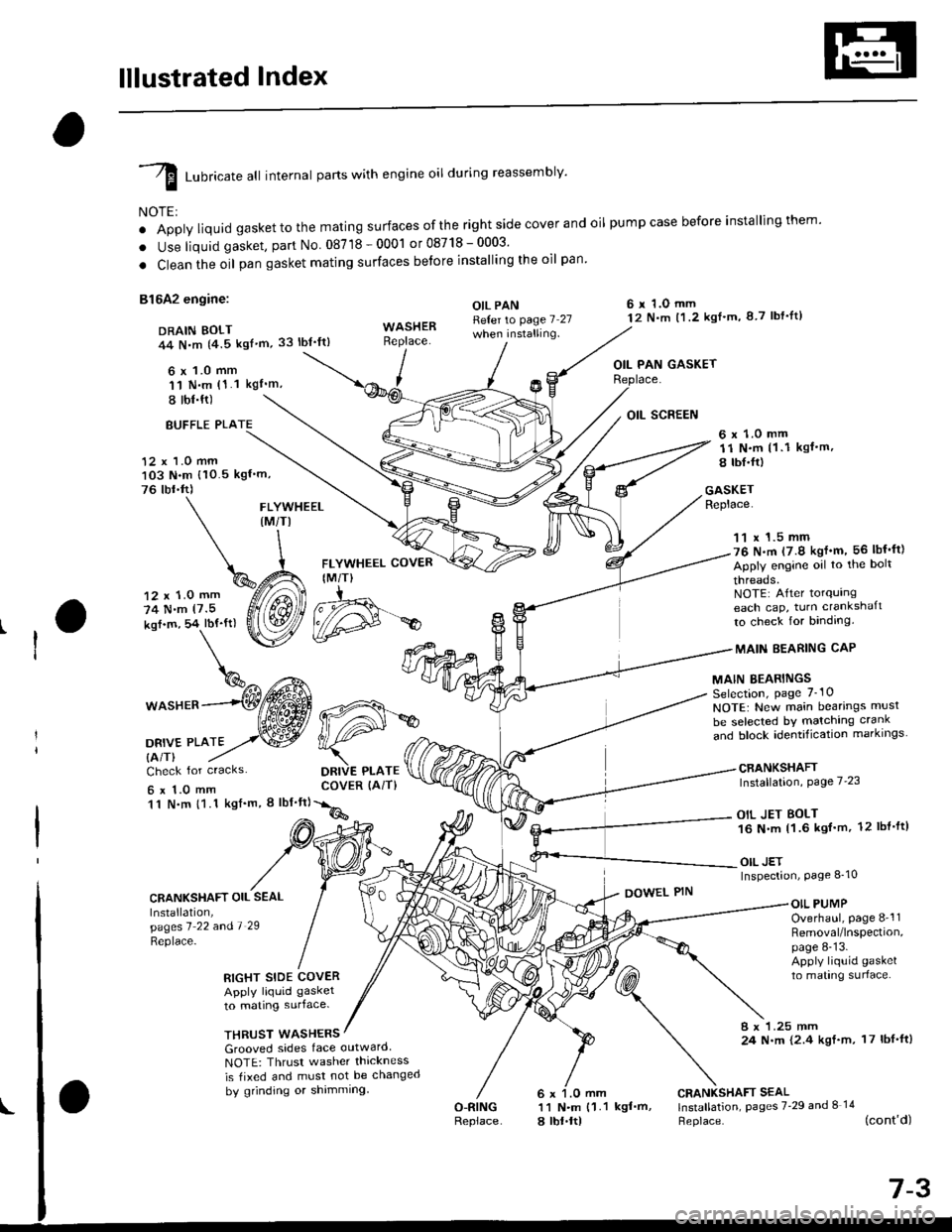
lllustrated Index
I runricate att internal parts with engine oil during reassembly'
NOTE:
o Apply liquid gaskettothe mating surfaces ofthe right side cover and oil pumpcase before installingthem'
. Use liquid gasket, part No 08718-0001 or08718-0003'
. Clean the oil pan gasket mating surfaces betore installing the oil pan
81642 engine:
DRAIN BOLT44 N,m {4.5 kgf'm,33 lbt'ft)
6 x 1.0 mm'11 N.m (1.1 kgI'm,
I tbl.ft)
OIL PANReter to page 7 27when installing.
6 r 1.O mm12 N.m t1.2 kgl'm, 8 7 lbf'lt)
OIL PAN GASKET
BUFFLE PLA
12 x 1.0 mm103 N.m {10.5 kgf'm,
76 tbr.ft)
6 x 1.0 mm11 N.m (1 .1 kgf.m,
8 tbI.fr)
GASKETReplace.FLYWHEEL(M/TI
12 x 1.0 mm
74 N.m (7.5
kof.m, 54 lbf'ft)
1^c{Eb\%^ t*^
*o"rr^--(Wffi
oa*,trto2,.w
FLYWHEEL COVER
IM/T)
DRIVE PLATECOVER (AiT)
11 x 1.5 mm76 N.m (7.9 kgf'm, 56 lbf'ft)
Apply engine oil to the bolt
threads.NOTE: After torqurngeach cap, turn crankshaft
to check for binding.
MAIN EEARING CAP
MAIN BEARINGSSelection, page 7_10
NOTE: New main bearings musl
be selected bY matching crank
and block identification markrngs
CRANKSHAFTInstallation, Page 7'23
OIL JET BOLT16 N.m 11.6 kgf'm, 12 lbl'ft)
OIL JETInspection, Page 8_10
Check for cracks
6x1.0mm11 N.m {1.1 kgf'm, I lbf'ft}
CRANKSHAFT OIL SEAL
Installation,pagesl 22 andl 29
Replace-
DOWEL PINOIL PUMPOverhaul, page 8-'l1Removal/lnspection,page 8-13.Apply liquid gasket
to mating surlace.RIGHT SIDE COVERApply liquid gasket
to mating surface.
THRUST WASHERS8 x 1.25 mm24 N.m {2.4 kgf.m, 17 lbf'ft)Grooved sides face outward
NOTE: Thrusr washer thickness
is tixed and must not be changed
by grinding or shimming
O-RINGReplace
CRANKSHAFT SEAL11 N.m {1.1 kgf'm, lnstallation, pages 7'29 and I 14
a lbt.ltl Heplace. (cont'd)
d#*
Page 202 of 2189

D16Y5, D16Y8 engines:
DRAIN BOLT39 N.m 14.0 kgt'm,
Apply liquid gasket to
these points.
OIL PANRefer to page 7-25
when installing.WASHERReplace.
29 lbl.tt)
\
\^
6 x 1.0 mm q%
P
I
FLYWHEEL COVER(M/T}
12 x 1.0 mm118 N.m(12.0 kgt.m, 87 lbt'ft)
FLYWHEEL (M/TI
t2 N.m 11.2 kgf'm,
8.7 lbl.ftl
11 x 1.5 mm
51 N.m(5.2 kgf'm, 38 lbf ftl
Apply engine oiltothe bolt
threads.NOTE: Aftertorquingeach cap, turn crankshaft
to check for binding.
MAINBEARING
MAIN BEARINGSSelection, page 7-10NOTE: New main bearings must
be selected by matching crank
"nJ lr."i io"irriti"",ion-markings. --------*-i6{\
CRANKSHAFTInstallation, page 7-23
6 r 1.0 mm11 N.m (1 1 kgf'm, I lbf'ttl
OII PAN GASKETReplace.
DRIVE PLATE COVER
{A/T or CVT)
12 r 1.0 mm
74 N.m
17.5 kgl.m, 54 lbf'ft)
DBIVE PLATE {A/T or CVTI
Check for cracks
6 x 1.O mm11 N.m {1.1 kgl'm,
8 tbl.ftl
CRANKSHAFT OIL SEAL
lnstallation,pages 7'?1 and '1 '28
Replace.
RIGHT SIDE COVER
Apply liquid gasket
to mating surface.
OIL SCREEN
GASKETReplace.
OIL PUMPOverhaul, page 8_12Removal/lnspection,page 8-13Apply liquid gasket
to mating surface.
DOWEL PIN
WASHEFS
Grooved sides tace outward
NOTE: Thrust washer thickness
is fixed and must not be changed
bV grinding or shimming.
CRANKSHAFT SEALInstallation, pages 7 29
and 8-14Replace.
BREATHING PORT COVER
MOUNT BOLTS6 x 1.O mm11 f{..n (1.1 kgf'm, 8 lbf'fl)
Apply liquid gasket to
the bolt threads.
O.RINGReplace.
6 x 1.0 mm
11 N.m (1 1 kgl'm,
8 tbr.ftl
(cont'd)
7-5
\
OOWEL PIN
Page 204 of 2189
Flywheel and Drive Plate
Replacement
Manual Transmission:
816A2 engine:
Remove the eight flywheel bolts, then separate the fly-
wheel from the crankshaft flange. After installation'
tiohten the bolts in the sequence shown
RING GEAR HOLDER "-i
OTLAB PVOOlOO
D16Y5, D16Y7, D16Y8 engines:
Remove the six flywheel bolts, then separate the flywheel
from the crankshaft flange. After installation, tighten the
bolts in a crisscross Pattern.
RING GEABInspect ring gear
teeth lor wear or
damage.
RING GEARInspect ring gear
teeth lor wear orteetn lor wea( or /danase. ,///.'
12 x 1.0 mm103 N.m(10.5 kgf.m, 76 lbf.tt)
12 x 1.o mm1 18 N,m(12.0 kgI.m, 87 lbf.ftl
L
rurS;u'.\
$..3s'
Automatic Transmission:
Remove the six drive plate bolts, then separate the drive
olate from the crankshaft flange. Atter installation, tighten
the bolts in a crisscross Pattern.
t7.5 kgl.m, 54 lbl'ltl
12 x 1.0 mm74 N.m
7-7
Page 209 of 2189
Pistons and Crankshaft
Removal
1. Remove the oil pan assembly.
2. Remove the right side cover.
816A2 engine
D16Y5, Dl6Y7, D16Y8 ongines
RIGHT SIDE
7-12
\
3. Remove the oil screen.
4. R€move the oil pump.
816A2 engin€
OIL SCREEN
D16Y5, D1oyr, D16Y8 engin.s
O-RINGReplace.
5, Remove the baffle plate (816A2 engine).
OIL PUMP
Page 229 of 2189
lllustrated Index
NOTE:
. Use new O-rings when reassembling
. Apply oil to O-rings before installation
. Use liquid gasket, Part No 08718 - 0001 or 08718 -
0003.
CAUTION: Do not overiighten the drain bolt.
6x1.0mm12 N.m (1.2 kqtm,8.7 lbl.ftl. Clean the oil
Ing.
B1642 engine:
pan gasket mating surlaces before install-
WASHERRePlace'
DRAIN BOLT44 N.m (4.5 kgl'm,33 lbt'ft)
Do not overtrghten.
6x1.0mm11 N.m (1.1 kgtm,
OIL PANReler to page 7'27
when installing.
OIL PANGASKETReplace-
6x1.0mm11 N'm (1.1 kgl.m,8 lbf.ft)
OIL BREATHERCHAMEER8
otLSCREEN
GASKETReplace.
€!
fl
[50
BAFFLE PLATE
OIL JET BOLT16 N'm 11.6 kgf.m, 12lbt'ttl
OIL JETInspection, page 8-10
8x1+5mm24 N.d\l2.il kgf.ft,t7 tbtft)
OIL FILTERReplace.
ENGINE OIL PRESSURE SWITCH
Pipe Taper) 28 Threads/inch Clean
Use proper liquid sealant.
6x1.0mm11 N.m 11.1 kgt m,8 tbt.frl
Overhaul. page 8'11Removal/lnspection, Page 8-13
Apply liquid gasket to (cont,d)mating surface of engine block
Replacemenl, page 8-8
Replace.
8-3
Page 231 of 2189
NOTE:
. Use new O-rings when reassembling.
. Apply oil to O-rings before installation.
. Use liquid gasket, Part No 08718 - 0001 or 08718 -
0003.
. Clean the oil pan gasket mating surfaces before install-
Ing.
D16Y5, D16Y8 engines:
O.RINGReplace.
OIL PUMPOverhaul, Page 8 12
Inspection, Page 8 13 OOWEL PINApply liquid gasket
to the mating surface
of the block.
CAUTION: Do not overtightsn the drain bolt.
ENGINE OIL PRESSURE SWITCH18 N,m l'1.8 kgf.m, 13 lbf.ftl
1/8 in. ESPT (British
Standard Pipe Taper)28 Threads/inch. useproper liquid sealant.
O-RING
OIL BREATHERCHAMBER
6x1.0mm11 N.m {1.1 kgf.m,I tbt'ftl
6 x'1.0 mm11 N.m ('1.1 |8 tbf.ft)
GASKETReplace.
FILTERReplacement, page 8_8
BAFFL€ PLATE
6x1.0mm11N.m 11.1 kgl.m,8 tbf.ftl
6x1.0mm11 N.m 11.1 kg{'m,
8 rbf.ftl
OIL PANGASKETFeplace.
OIL PANReler to page 7 26when installing.
\3
6x1.0mm12 N.m {1.2 kg{.m,8.7 lbf ftl
BOLT39 N.m (4.0 kgf.m.29lbtftlDo not overtighten.
\
8-5
Page 568 of 2189
J
t
Clutch
Speciaf Tools .......... ...........12-2
f lfustrated Index .......... ......12-3
clutch Pedal
Adjustment .................... 12'4
Clutch Master Cylinder
Removal/lnstallation ..... 12-5
Slave Cylinder
Removal/lnstallation .....12'6
Pressure Plate
Removal/lnspection ...... 12-7
Clutch Disc
Removal/lnspection ...... 12-8
Flywheel
Inspection ....................... 12-9
Replacement ....................................... 12-9
Clutch Disc, Pressure Plate
lnstallation ..................... 12-10
Release Bearing
Removal/lnspection ......12-11
f nstalfation .................,... 12-12
\