1996 HONDA CIVIC Valve timing
[x] Cancel search: Valve timingPage 492 of 2189

\
I
'98 - 0O D16Y5 ongine with CvT
Adjust the idle speed using a Honda PGM Tester if pos-
sible. lf not, use the following procedure:
NOTE:
. Leave the IAC valve connected.
. Before s€tting the idle speed, check the following
rtems:- The MIL has not been reported on.
- lgnition timing
- Spark Plugs- Air clean€r
- PCV svstem
'1. Connect a tachometer.
2. Stan the engine. Hold the engine at 3,000 rpm w'th
no load (transmission in E or E] position) until the
radiator Jan comes on, then let it idle.
3. Check the idle speed under no-load conditions:
head lights, blower fan, rear defogger, radiator fan,
and air conditioner are not operatlng.
ldlo spaod ehould bo: 700 t 50 rpm
. lf the idle speed is within the specification, the
procedure is comPlete.
. lf the idle sDeed is out of specitication, 9o to step 4'
4. tf the idle speed is 810 1 50 rpm, this means the
EVAP system is purging the canister. To stop the
purging temporarily, raise the engine speed above
l,OO0 rgm with the accelsrator pedal. Slowly release
the pedal. and rscheck the idl€ speed.
. tf the idle speed is within the specificstion, the
Drocedure is comPlete.
. lf the idle sp€ed is out of spocification, go to step 5.
5. Disconnect th€ EVAP purgs control solenoid valve
2P connector.
EVAP PURGECONTROL
6. Remove the cap and turn the idle adiusting screw
1/2-turn clockwise or counterclockwlse
IDLE
7.After turning the idle adjusting screw 1/2-turn, check
the idl€ speed again. lf it is out of spec, turn the idle
adjusting screw 1/2-turn again.
NOTE: Do not turn the idle adjusting screw more
than 1/2-turn without checking the idle speed.
Turn the ignition switch OFF. Reconnect the EVAP
purge control solenoid valve 2P connector' then do
the ECM reset Procedure.
Start the engine. ldle the engine for one minute with
heater fan switch at Hl and air conditioner on, then
check the idle speed.
ldle spaed should be:
810 t 50 rpm (in El or E Posiiion)
lf the idle speed is not within specification, see
Svmptom Chart on Page 11-84.
9.
SOLENOID VALVE
11-223
Page 681 of 2189

Description
The automatic transmission is a 3-element torque converter and a dual-shaft electronically controlled unit which provides
4 soeeds forward and 1 reverse.
Torque Convertel, Geats, and Clutches
The torque converter consists of a pump, turbine and stator, assembled in a single unit. They are connected to the engine
crankshaft so they turn together as a unit as the engine turns. Around the outside of the torque converter is a ring gear
which meshes with the starter pinion when the engine is being started. The entire torque converter assembly seryes as a
flywheel while transmiuing power to the transmission mainshaft.
The transmission has two parallel shafts: the mainshaft and the countershaft. The mainshaft is in Iine with the engine
crankshaft. The mainshaft includes the 1st, 2nd and 4th clutches, gears tor 2nd, 4th, reverse and lst (3rd gear is integral
with the mainshaft, while the reverse gear is integral with the 4th gear). The countershaft includes the 3rd clutch, and
gears for 3rd,2nd, 4th, reverse. 1st and park. The gears on the mainshaft are in constant mesh with those on the counter-
shaft. When certain combinations of gears in transmission are engaged by clutches. power is transmitted from the main-
shaft to the countershaft to provide E, ld, E, and E positions.
Electronic Control
The electronic control svstem consists of the Powertrain Control Module {PCM), sensors, a linear solenoid and four
solenojd valves. Shifting and lock-up are electronically controlled for comtonable driving under all conditions. The PCM is
located below the dashboard, under the front lower panel on the passenger's side
Hydraulic Control
The valve bodies include the main vatve body, the secondary valve body, the regulator valve body, the servo body and the
lock-up valve body through the respective separator plates, They are bolted on the torque converter housang
The main valve body contains the manual valve, the 1-2 shift valve. the 2nd orifice control valve, the CPB {Clutch Pressure
Back-up) valve, the modulator valve. the servo control valve, the relief valve, and ATF pump gears The secondary valve
body contains the 2-3 shift valve. the 3-4 shift valve, the 3-4 orifice control valve, the 4th exhaust valve and the CPC (Clutch
pressure Control) valve. The regulator valve body contains the pressure regulator valve, the torque converter check valve,
the cooler relief valve, and the lock-up control valve. The servo body contains the servo valve which is integrated with the
reverse shift fork, and the accumulators. The lock-up valve body contains the lock-up shift valve and the lock-up timing
valve. The linear solenoid and the shift control solenoid valve Ay'B are bolted on the outside of the transmission housing,
and the lock-up control solenoid valve Ay'B is bolted on the outside of the torque converter housing. Fluid from regulator
passes through the manual valve to the various control valves. The clutches receive fluid from their respective teed pipes
or internal hydraulic circuit.
Shift Control Mechanism
Input from various sensors located throughout the car determines which shift control solenoid valve the PCM will activate
Activating a shift control solenoid valve changes modulator pressure, causing a shift valve to move. This pressurizes a line
to one of the clutches, engaging that clutch and its corresponding gear, The shift control solenoid valves A and B are con-
trolled by the PCM.
Lock-up Mechanism
In ,Dt1 position, in 3rd and 4th. and in E position in 3rd, pressurized fluid is drained from the back of the torque converter
through a fluid passage, causing the lock-up piston to be held against the torque converter cover. As this takes place, the
mainshaft rotates at the same as the engine crankshaft. Together with hydraulic control, the PCM optimizes the timing of
the lock-up mechanism. The lock-up valves control the range of lock-up according to lock-up control solenoid valves A and
B, and linear solenoid. When lock-up control solenoid valves A and B activate, the modulator pressure changes The lock-
up control solenoid valves A and B and the linear solenoid are controlled by the PCM.
(cont'd)
14-3
Page 699 of 2189

\
Regulator Valve BodY
The regulator valve body is located on the main valve body. The regulator valve body consists of the regulator valve' the
torque-converter check valve, the cooler relief valve, and the lock-up control vaive'
REGULATOR VALVE
BODY
REGULATOR VALVE
COOLER RELIEF VALV€
LOCK,UP SHIFT VALVE
CONVERIER
CHECK VALVE
CONTROL VALVE
Lock-up Valve BodY
The lock-up valve body with the lock-up shift valve and the lock-up timing valve is located on the regulator valve bodv
LOCK-UP NMING VALVE
icont d
1+21
Page 712 of 2189

Description
Lock-up System (cont'd)
TOROUE CONVERTER
In B.rl position, in 3rd and 4th, and lDl_- position in 3rd.pressurized fluid is drajned from the back of the torqueconverter through a fluid passage. causing the lock-uppiston to be held against the torque convener cover. Asthis takes place, the mainshaft rotates at the same speedas the engine crankshaft, Together with the hydrauliccontrol, the PCM optimized the timing of the lock_upsystem. Under certain conditions, the lock_up clutch isapplied during deceleration, in 3rd and 4th gear.
The lock-up system controls the range of lock_up accord_ing to lock-up control solenoid valves A and B. and thelinear solenoid. When lock-up control solenoid valves Aand B activate, modulator pressure changes. Lock_upcontrol solenoid valves A and B and the linear solenoidare mounted on the outside of the torque converterhousing. and are controlled by the pclvl.
Lock-up Conditions/Lock-up Control Solenoid Valves/Linear Solenoid Pressure
MODULATOR PRESSURE
.-- LINEAR SOLENOID PRESSURE
LOCK.UP CONTROL. VALVE
LOCK.UP CONTROLSOLENOID VALVELock-up
Conditions
Lock-up Control
Solenoid ValveLineal
Solenoid
PressureAB
Lock-up OFFOFFOFFHig h
Lock-up. HalfONDuty operation
OFF - ON
Lock-up. FullONONHigh
Lock-up
during
decelerationONDuty operation
OFF * ONLowTOROUE CONVERTERCHECI( VALVE
RELIEF VAI-VE
LOCK.UP TIMINGVALVE
^ r______rr r cooLER RELTEF VALVE
t'-
14-34
ATF PUMP
Page 713 of 2189

I
TOROUE CONVERTER
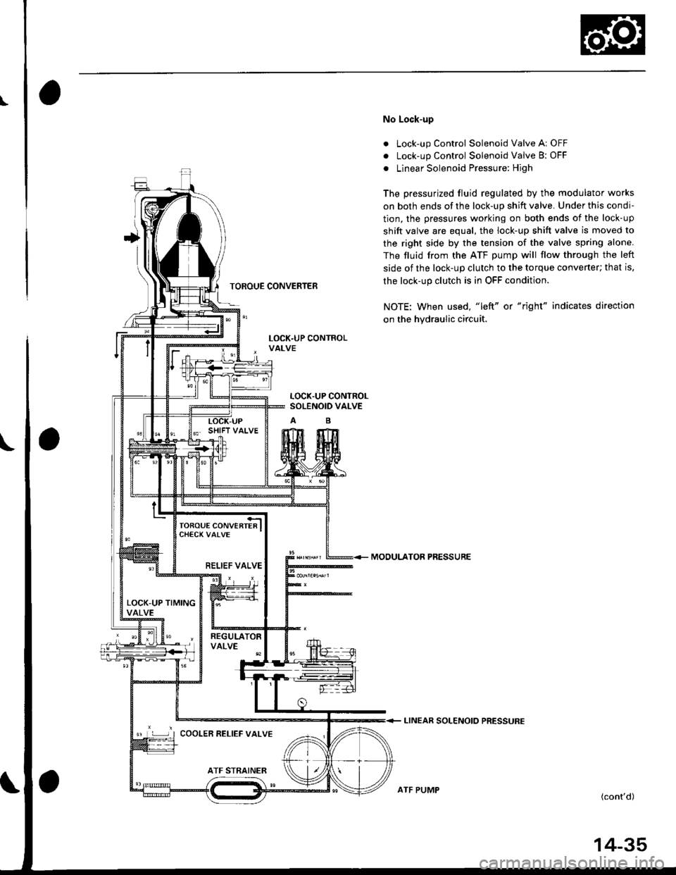
No Lock-up
. Lock-up Control Solenoid Valve A: OFF
. Lock-up Control Solenoid Valve B: OFF
. Linear Solenoid Pressure: High
The pressurized fluid regulated by the modulator works
on both ends of the lock-up shift valve. Under this condi-
tion, the pressures working on both ends of the lock-up
shift valve are equal, the lock-up shift valve is moved to
the right side by the tension of the valve spring alone.
The fluid from the ATF pump will flow through the left
side of the lock-up clutch to the torque convener; that is,
the lock-up clutch is in OFF condition.
NOTE: When used, "left" or "right" indicates direction
on the hydraulic circuit.
MOOULATOR PRESSURE
LINEAR SOLENOIO PRESSURE
(cont'd)
LOCK.UP CONTROLSOLENOID VALVE
RELIEF VALVE
LOCK-UP TIMINGVALVE
9 L ] I COOLER RELIEF VALVE
ATF PUMP
14-35
Page 714 of 2189

Description
Lock-up System (cont'dl
TOROUE CONVERTER
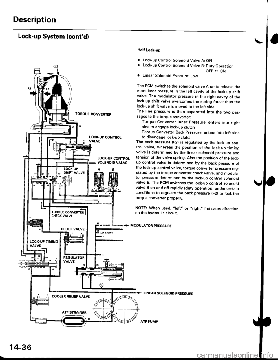
Half Lock-up
. Lock-up Control Solenoid Valve A: ONLock-up Control Solenoid Valve 8: Duty Operation
OFF - ONLinear Solenoid Pressure: Low
The PCM switches the solenoid valve A on to release themodulator pressure in the left cavity of the lock_up shiftvalve. The modulator pressure in the right cavity of thelock-up shift valve overcomes the spring force; thus thelock-up shift valve is moved to the left side.The line pressure is then separated into the two pas-sages to the torque converter:
Torque Converter Inner pressure: enters into rightsade to engage lock-up clutch
Torque Converter Back pressure: enters into left sideto diseogage lock-up clutchThe back pressure (F2) is regulated by the lock-up con-trol valve, whereas the position of the lock-up timingvalve is determined by the linear solenoid Dressure andtension of the valve spring. Also the position of the lock_up control valve is determined by the back pressure ofthe lock-up control valve, torque converter pressure reg_ulated by the torque converter check valve, and modula_tor pressure determined by the lock-up control solenoidvalve B. The PCM switches the lock-up control solenoidvalve B on and off rapidly {duty operation} under certainconditions to regulate the back pressure (F2) to lock thetorque convener properly.
NOTE: When used, "left" or "right" indicates directionon the hvdraulic circuit.
MODULATOR PRESSURE
LINEAR SOLENOTD PRESSURE
LOCK.UP CONTROLVALVE
LOCK.UP CONTROLSOI.TNOID VALVE
A8
TOROUE CONVERTERCHECK VAI-VE
RELIEF VALVE
LOCK-UP TIMINGVALVE
^ L____J'r cooLER RELTEF valvE
14-36
ATF PUMP
Page 715 of 2189

TOROUE CONVERTER
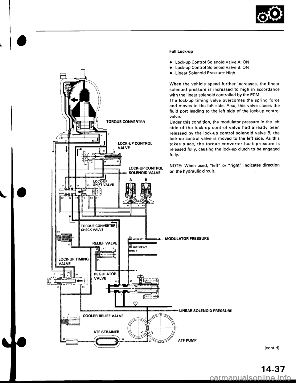
Full Lock-up
. Lock-up Control Solenoid Valve A: ON
. Lock-up Control Solenoid Valve B: ON
o Linear Solenoid Pressure: High
When the vehicle speed further increases. the linear
solenoid pressure is increased to high in accordance
with the linear solenoid controlled bv the PCM.
The lock-up timing valve overcomes the spring force
and moves to the left side. Also, this valve closes the
fluid port leading to the left side of the lock-up control
Under this condition. the modulator pressure in the left
side of the lock-up control valve had already been
released by the lock-up control solenoid valve B; the
lock-up control valve js moved to the left side. As this
takes place, the torque converter back pressure is
released fully. causing the lock-up clutch to be engaged
fully.
NOTE: When used, "|eft" or "right" indicates direction
on the hvdraulic circuit.
MODULATOR PRESSURE
LINEAR SOLENOIO PRESSURE
{cont'd)
LOCK.UP CONTROLSOLENOID VALVE
RELIEF VALVE
LOCK.UP TIMINGVALVE
'r ,-.r' cooLER RELTEF vALvE
ATF PUMP
14-37
Page 716 of 2189

Description
Lock-up System (cont'dl
TOROUE CONVERTER
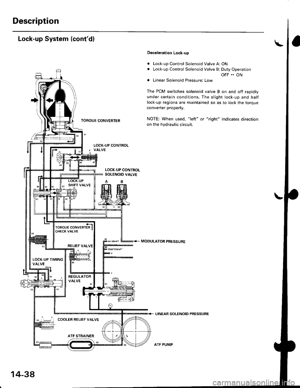
Deceleration Lock-up
. Lock-up Control Solenoid Valve A: ON. Lock-up Control Solenoid Valve B: Duty Operation
OFF - ONa Linear Solenoid Pressure: Low
The PCM switches solenoid valve B on and off rapidly
under certain conditions. The slight lock-up and half
lock-up regions are maintained so as to lock the torque
converter properly.
NOTE: When used, "left" or "right" indicates direction
on the hydraulic circuit,
MOOULATOR PRESSURE
LINEAR SOLENOID PRESSURE
LOCK-UP CONTROLSOLENOID VALVE
RELIEF VALVE
LOCK.UP TIMINGVALVE
COOLER RELIEF VALVE
ATF STRAINER
1434
ATF PUMP