1996 HONDA CIVIC DTC chart
[x] Cancel search: DTC chartPage 557 of 2189
Emission Control System
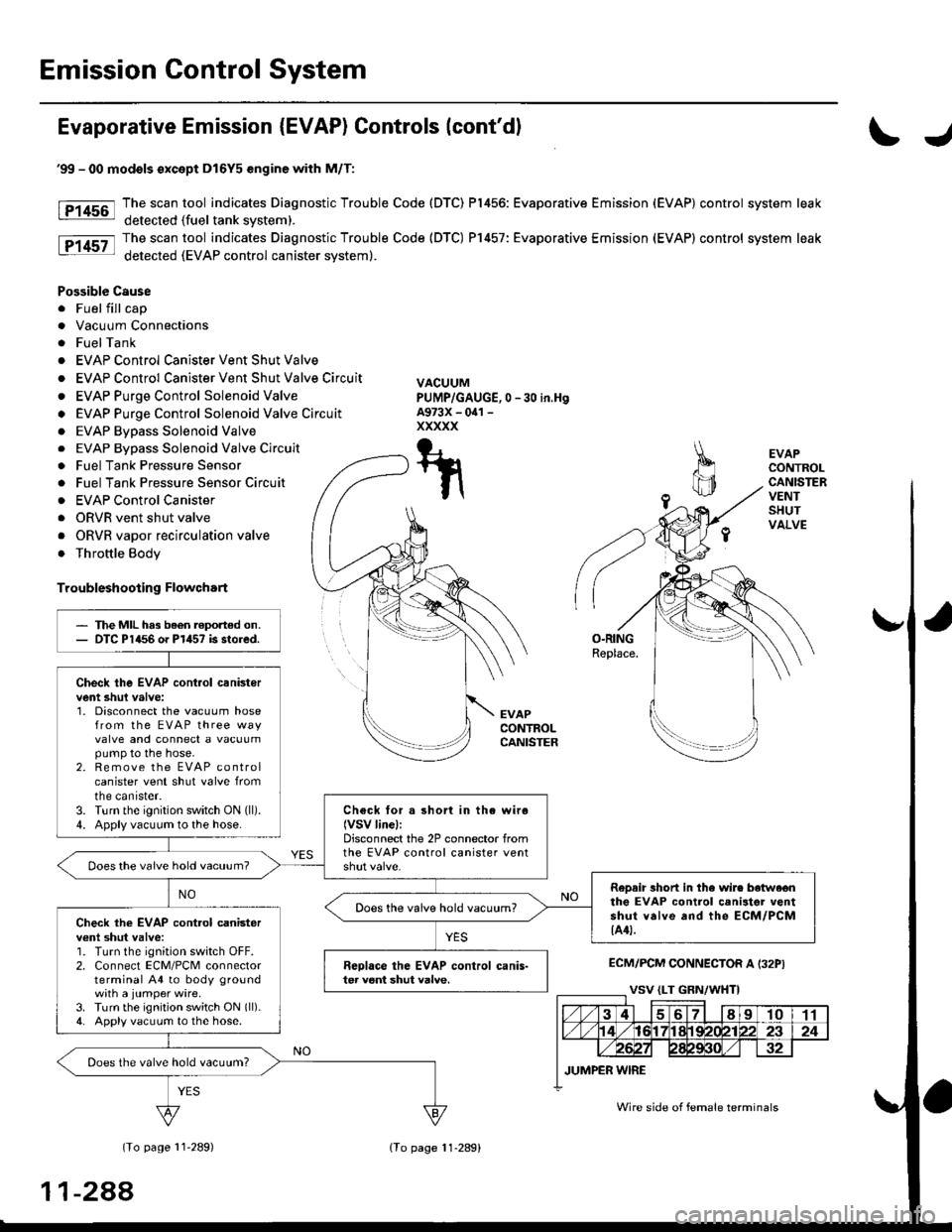
Evaporative Emission {EVAP) Controls (cont'dl
\J
tF1456-l
tP14sz-l
EVAPCONTROLCANISTERVENTSHUTVALVE
O.RINGReplace.
EVAPCONTROLCANISTER
ECM/PCM CONNECTOR A I32PI
(To page 11'289)
'99 - 00 modols except Dl6Y5 engine with M/T:
The scan tool indicates Diagnostic Trouble Code (DTC) P1456: Evaporative Emission (EVAP) control system leak
detected (fuel tank svstem).
The scan tool indicates Diagnostic Trouble Code (DTC) P1457: Evaporative Emission (EVAP) control system leak
detected (EVAP control canister system).
Possible Cause
. Fuel fill cap
. Vacuum Connections
. FuelTank
. EVAP Control Canister Vent Shut Valve
. EVAP Control Canister Vent Shut Valve Circuit
. EVAP Purge Control Solenoid Valve
o EVAP Purge Control Solenoid Valve Circuit
. EVAP Bypass Solenoid Valve
0 -30 in,Hg
. EVAP Bypass Solenoid Valve Circuit
. Fuel Tank Pressure Sensor
. Fuel Tank Pressure Sensor Circuir
. EVAP Control Canister
. ORVR vent shut valve
. ORVR vapor recirculation valve
. Throttle Body
Troubleshooting Flowchart
VACUUMPUMP/GAUGE,A973X - oal -
xxxxx
T-t
t\
The MIL has been reported on.DTC P1456 o. P1457 is stored.
Check the EVAP cont.ol canistervent shul valve:1. Disconnect the vacuum hosefrom the EVAP three wayvalve and connect a vacuumpump to the hose.2. Remove the EVAP controlcanister vent shut valve fromtne canrster.3. Turn the ignition switch ON (ll).
4. Apply vacuum to the hose.Check for a short in the wiro(VSV linel:Disconnect the 2P connector fromthe EVAP control canister ventDoes the vaive hold vacuum?
RoDair 3hort in the wire botwe€nthe EVAP control canilter ventshut valve and the ECM/PCM{A4t.
Does the valve hold vacuum?Check the EVAP cont.ol canisterv€nl shut valve:1. Turn the ignition switch OFF.2. Connect ECM/PCM connectorterminal A4 to body groundwith a jumper wire.3. Turn the ignition switch ON (ll).
4. Apply vacuum to the hose.
Reolace the EVAP control canis-ter veni shut valve.
Does the valve hold vacuum?
Wire side of female terminals
11-288
lTo page 11-289)
Page 726 of 2189
Troubleshootin g Procedures
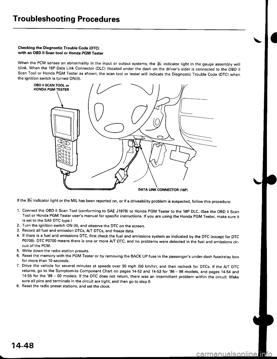
Chccking the Diagnostic Trouble Code IDTC)with an OBD ll Scan tool or Honda PGM Tester
when the PCM senses an abnormality in the input or output systems, the pl indicator light in the gauge assembly willblink. When the 16P Data Link Connector (DLC) (located under the dash on the driver,s side) is connected to the OBD llScan Tool or Honda PGM Tester as shown, the scan tool or tester will indicate the Diagnostic Trouble Code (DTC) whenthe ignition switch is turned ON{ll).
lf the El indicator light or the MIL has been reported on, or lf a driveability problem is suspected, follow this procedure:
1. Connect the OBD ll Scan Tool (conforming to SAE J19781 or Honda PGM Tester to rhe 16p DLC. (See the OBD ll ScanTool or Honda PGM Tester user's manual for specific instructions. lf you are using the Honda PGM Tester, make sure itis set to the SAE DTC type.)
2. Turn the ignition switch ON (lll, and observe the DTC on the screen,3, Record all fuel and emission DTCS, A/T DTCS, and freeze data.4 lf there is a fuel and emissions DTC, first checkthe fuel and emissions system as indicated bythe DTC (except for DTCP0700). DTC P0700 means there is one or more A,/T DTC, and no problems were detected in the fuel and emissions cir-cuit of the PCM.
5. Write down the radio station oresets.
6. Reset the memory with the PGM Tester or by removing the BACK UP fuse in the passenger's under-dash fuse/relay boxfor more than 10 seconds.
7. Drive the vehicle for several minutes at speeds over 30 mph (50 km/hr), and then recheck for DTCS. lf the A"/T DTCreturns, go to the Symptom-to Component Chart on pages 14-52 and 14-53 for'96 - 98 models, and pages 14-54 and14-55 for the'99 - 00 models, lf the DTC does not return, there was an intermittent problem within the circuit. Makesure all pins and terminals in the circuit are tight, and then go to step g.
8. Reset the radio preset stations, and set the clock.
OBD ll SCAN TOOL orHONDA PGM TESTER
DAYA LINK CONNECTOR {16P}
14-44
Page 727 of 2189
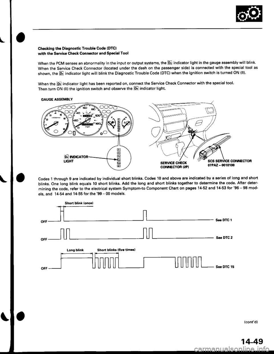
Chocking th€ Diagnostic Trouble Code (DTCI
with the Servico Check Conneqtor and Sp€cialTool
When the PCM senses an abnormality in the input or output systems, the @ indicator light in the gauge assembly will blink
When the Service Check Connector (locat€d under the dash on the passengsr side) is connected with the special tool as
shown, the E indicator light will blink the Diagnostic Trouble Code (DTC) when the ignition switch is turned ON (ll).
When the E indicator light has been reported on, connect the Service Check Connector with the special too'.
Then turn ON (ll) the ignition switch and obssrve the E indicator tight.
CONNECTOBSERVICE CHECKCONNECTOR I2PI07PAZ -0010100
Codes 1 through 9 are indicated by individual short blinks, Codes 10 and above are indicat€d by a sories of long and short
blinks. One long blink equals 1O short blinks. Add the long and short blinks together to determine th€ code. After deter-
mining the code, refer to the electrical system Symptom-to Component Chart on pages 1+52 and 1+53 for'96 - 98 mod-
els, and 14-54 and 14-55 for the '99 - 00 models.
S€r DTC 1
s.. DTC 2
Long blinkShort blink lfiYa tim.!,
S€c DTC 15
(cont'd)
GAUGE ASSEMBLY
Short blink loncel
14-49
Page 732 of 2189

Symptom-to-Component Chart
Electrical System -'99 - 00 Models
*1: The DTc in the parentheses is the code E indicator tight indicates when the Data Link connector is connected to theHonda PGM Tester.*2: Whenever the Honda PGM Tester or scan Tool detects an automatic transmission control system DTc, p07oo will beset in the PGM-FI control svstem
DTC*IE Indicator
LightMILDotostion ltemPage
P1753
fi)BlinksONLock-up control solenoid valve A'14-80
P1758
t2lBlinksONLock-up control solenoid valve B14-82
P1705
{5}BlinksONAy'T gear position switch {short to ground)14-84
P1706
(6)OFFONy'VT gear position switch {open)14-81
P0753
\71BlinksONShift control solenoid valve A14-89
P0758
(8)BlinksONShift control solenoid valve B14-9r
P0720
(9)BlinksONCountershaft speed sensorr4-93
P0715
(15)B linksONMainshaft speed sensor14-95
P1768
(16)BlinksONLinear solenoid't 4-97
PO7 40(40)OFFONLock-up control system14-99
P0730
(41)OFFONShift control svstem14- 100
P0700*,
(none)OFFAutomatic transmission control system in the pGM_Fl
controt svstem
14-54
Page 752 of 2189
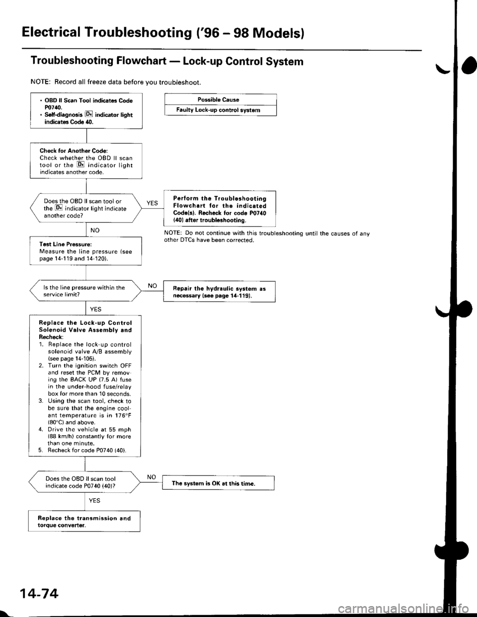
Electrical Troubleshooting ('96 - 98 Models)
Troubleshooting Flowchart - Lock-up Control System
NOTE: Record all freeze data before vou troubleshoot.
Possible Cause
Faulty Lock-up cont.ol system
NOTE: Do not continue with this troublesnoonnoother DTCS have been corrected.until the causes of any
. OBD ll Sc6n Tool indicatG Codem7{0.. Self-diagnosis E indicator lightindicates Code 40.
Check tor Another Code:Check whether the OBD ll scantool or the E indicato, lightindicates another code.
Perform lhe Troublo3hooiingFlowchart tor the indicatedCode(s). Recheck for cod. P07il0lilol aftor iroubl€3hooting.
Does the OBD ll scan tool orthe E indicator light indicateanother code?
Tast Line Pressure:Measure the line pressure (seepage 14-119 and 14-120).
Repair tho hydreulic aystem a3necessary {3ee page 14-119).
Replace the Lock-up ControlSolenoid Valve Assembly andR6check;1. Beplace the lock up controlsolenoid valve Ay'B assembly(see page 14-105).2. Turn the ignitaon switch OFFand reset the PCM by removing the BACK UP (7.5 A) fusein the underhood fuse/relaybox for more than 10 seconds,3. Using the scan tool, check tobe sure that the engine coolant temperature is in 176'F(80'C) and above.4. Drive the vehicle at 55 mph(88 km/h) constantly for morethan one minute.5. Recheck for code P0740 (40).
Does the OBD ll scan toolindicate code P0740 {40)?The systom k OK at this time.
l'.
14-74
Page 753 of 2189

Troubleshooting Flowchart - Shift Control System
NOTE: Record all freeze data before vou troubleshoot.
Possible Cause
Faulty shift control system
. OBD ll Scan Tool indicates CodeP0730.. Sell-diagnosis E indicator
light indicates Code ill.
Check tor Another CoderCheck whether the OBD ll scantool or the E, indicator lightindicate another code.
Perlorm ths TroubleshoolingFlowch.rt for the indic.t.dCode(sl. Recheck tor code m730
l4'l I atter troubleshooting.
Does the oBD ll scan tool orthe E indicato'. tight indicate another code?
Test lst, 2nd, 3rd and 4th Clutch
Pressure:Measure the 1st, 2nd, 3rd and 4th
clutch pressure (see page 14119
thru 14-121).
Ropair the hydrlulic systom !snecessary {see page 14-1 19 and11-1211.
ls each clutch pressure within
the service limit?
Replace Shift Control Solenoidvalve Assembly, Linear SolenoidAssambly and Rechock:1. Replace the shift controlsolenoid valve A'/B assembly(see page 14-106).2. Replace the linear solenoidassembly lsee page 14 108).3. Turn the ignition switch OFFand reset the PCM memory byremoving the EACK UP (7.5 A)tuse in the under hood fuse/relay box for more than l0
seconds,4. Drive the vehicle at over 12mph (20 km/h) in 1st, 2nd,3rd
and 4th gear for more than 30seconds at P1 position.
5. Recheck tor code P0730 (41).
Does the OBD ll scan tool orthe Ed indicator tight indi
cate code P0730 {41)?
The swt6m is OK et this time.
NOTE: Do not continue with this troubleshooting until the causes ot any
other DTCS have been corrected.
Page 777 of 2189
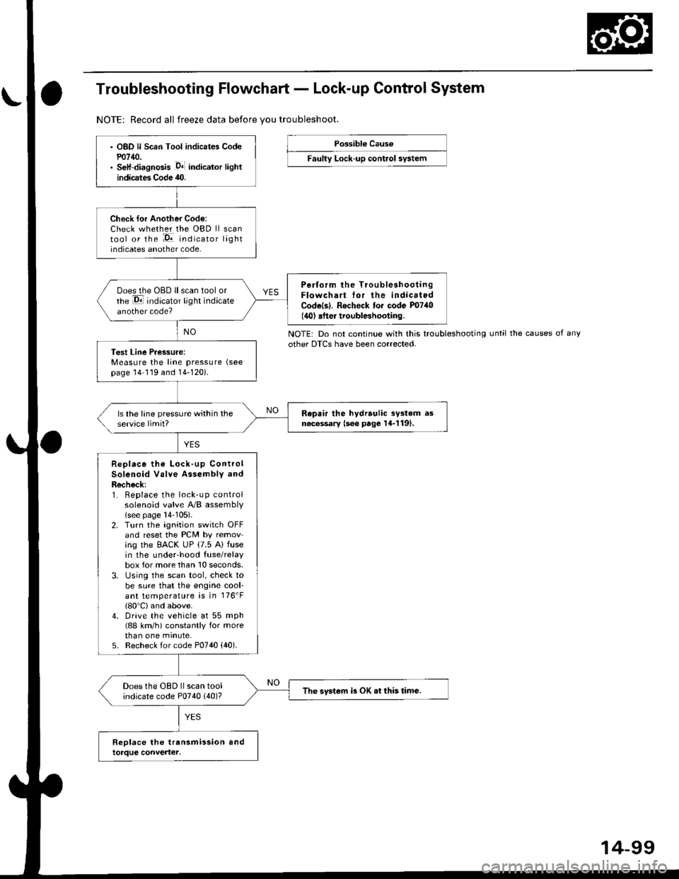
Troubleshooting Flowchart - Lock-up Control System
NOTE: Record all freeze data before vou troubleshoot.
Possibl€ Cause
Faulty Lock-up control sy3tem
NOTE: Do not continue with this troubleshootingother DTCS have been corrected.until the causes of any
OBD ll Scan Tool indicates Codem14/J.S€lf-diagnosis .D4l indicalor lightindicates Code 40.
Check for Another Code:Check whether the OBD ll scantool or the :E indicator lightindicates another code,
Perform the TroubleshootingFlowchart tor the indicatedCodels|. Rocheck to. code P0740(40) .fter troublBhooting.
ooes the OBD ll scan tool orrhe E indicator light indicateanother code?
Test Line Pressure:Measure the line pressure (see
page 14 119 and 14-120).
Repair the hydrrulic sy3tem asn6c6ssary (see page 14-1191.ls the lane pressure within theservice limit?
Replace the Lock-up ControlSolenoid Valve Assembly andRecheck:1. Replace the lock-up controlsolenoid valve A/B assembly(see page 14-105).2. Turn the ignition switch OFFand reset the PCM by removing the EACK UP (7.5 A) fusein the underhood {use/relaybox for more than 10 seconds.3. Using the scan tool, check tobe sure that the engine cool-ant temperature is in 176'F(80'C) and above.4. Drive the vehicle at 55 mph(88 km/h) constantly for morethan one minute,5. Recheck for code P0740 {40).
Does the OBD ll scan toolindicate code P0740 (40)?The svstem i3 OK .t this time.
14-99
Page 911 of 2189
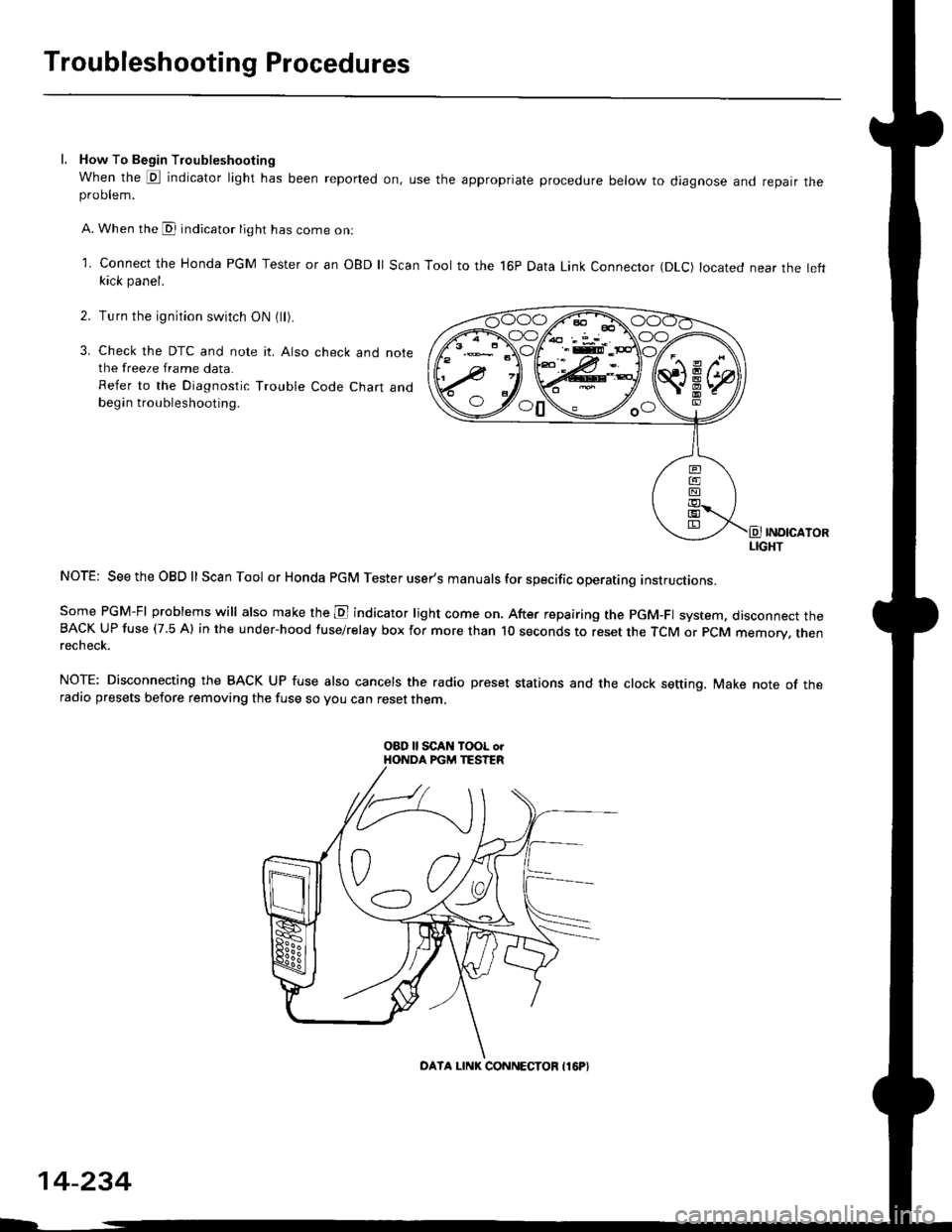
Troubleshooting Procedures
l. How To Begin Troubleshooting
When the E indicator light has been reported on, use the appropriate procedure below to diagnose and repatr theproDlem.
A. When the @ indicator light has come on:
l connect the Honda PGM Tester or an oBD ll Scan Tool to the 16P Data Link Connector (DLc) located near the leftkick panel.
Turn the ignition switch ON (ll).
Check the DTC and note it. Also check and notethe freeze frame data.
Refer to the Diagnostic Trouble Code Chart andbegin troubleshooting.
INOICATORLIGHT
NOTE: SeetheOBDll Scan Tool or Honda PGM Tester user's manuals for specific operating instructions.
Some PGM-FI problems will also make the E indicator light come on. After repairing the pGM-Fl system, disconnect theBACK UP fuse (7.5 Al in the under-hood fuse/relay box for more than l0 seconds to reset the TCM or PCM memory, rnenrecheck.
NOTE: Disconnecting the BACK UP fuse also cancels the radio preset stations and the clock setting. Make note of theradio presets before removing the fuse so you can reset them,
2.
3.
o0\e--loo
OATA LINK CONNECTOB I16P}
14-234