Page 1744 of 2189
Circuit Diagram
UNDER-HOOD FUSE/RELAY 8OXIGNITIONSWITCH
WHT/8LI( +WHT
Brake systsm light
passenger's airbag
l----ltlI DUMMY II BESISTOR I
tll
tl
la rl
MEMORY ERASESIGNAT IMES)CONNECTOR I2P)
GRY{GRN)
I
BRN BRN
tl.-l- .-r-\./ \./
ECM/PCM SERVICECHECKCONNECTOR
ILT 8LU
I
t'7
DATA LINKCONNECTOR{DLC) {r6P)
GRY GRY(GRN) IGNN)
V:
G801
Teminalside oi thal€ terminals
24-6
4''
SRS UNIT TERMINALSG40tG402
SBS INDICATOR CIRCUIT{ln the gauge assembly)
PGM_FI
DRIVER'SAIRBAGINFLATOR
10 14 r 13 6 7(VAl 3{VBlSRS UNIT16 17 t5 9 18 8
Page 1764 of 2189

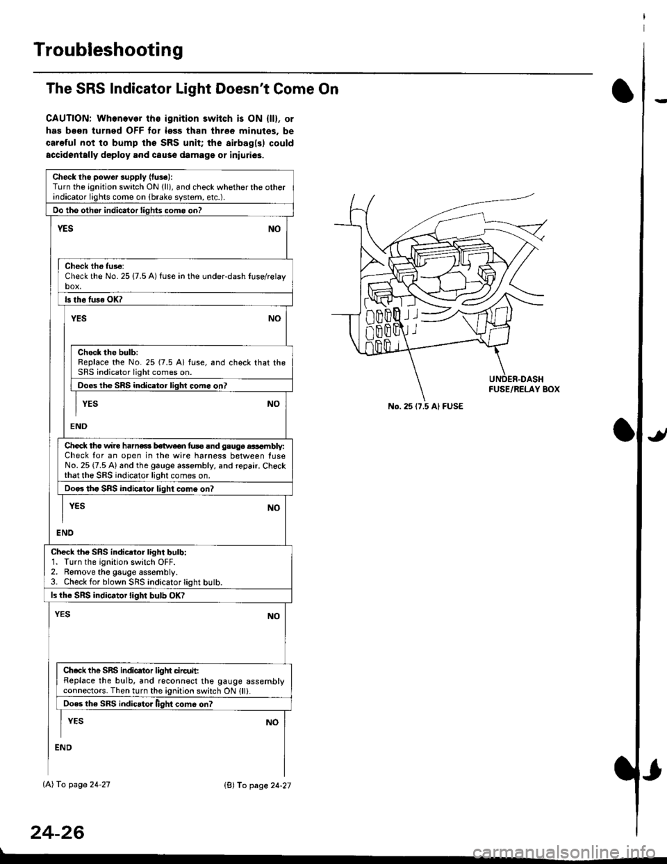
Troubleshooting
The SRS Indicator Light Doesn't Come On
CAUTION: Whonever ths ignition switch is ON {ll}, or
has been turned OFF tor less than three minutes. be
careful not to bump the SRS unit; the airbagls) could
accidentally deploy .nd caus6 damage or iniuri€s.
Check tho pow€r supply (fuse):
Turn the ignition switch ON (ll), and check whether the otherindicator lights come on (brake system, etc.).
Oo the other indicator liohts como on?
YESNO
Check th6 fuso:Check the No. 25 {7.5 A) fuse in the under-dash tuse/relayb"t
ls th6 tu36 OK?
NOYES
Check the bulb:Replace the No. 25 (7.5 A) fuse, and check that theSRS indicator light comes on.
Doos the SRS indicator liqhl come on7
I YES No
END
Check tho wire harns b€twecn fus6 and gauge aasambly:Check for an open in the wire harness between luseNo. 25 {7.5 A) and the gauge assembly, and repair. Checkthat the SRS indicator light comes on.
Doo. tho SRS indic.tor light como on?
I yEs No
I
END
Check tho SRS indicator light bulb:1. Turn the ignition switch OFF.2. Remove the gauge assembly.3. Check for blown SRS indicator light butb.
ls the SRS indicator light bulb OK?
NOYES
Ch.ck the SnS indicator liglrt circuit:Replace the bulb, and reconnect the gauge assemblyconnectors. Then turn the ignition switch ON {ll}.
Ooes th6 SRS indicato. llght come on?
I YEs No
:ND
lAl To page 24-27
24-26
lB'J fo page 24-27
))
No. 25 (7.5 Al FUSE
Page 1817 of 2189

Contents
How to Use This Manual ICircuit Schematics (see Circuit Index)Fuse/Relaylnformation 6Ground-to-Componentslndex 6-6ComponentLocationPhotooraohs 201Conriector Views 202
Circuit Index
Accessory power socket 155Air conditionerAir delivery'96198 models 61'99-'00 models 61-2Blower controls'96198 models 60'99100 models 60-1Compressor controls 62Fans 63Anti-lock brake system (ABS) 44A/T gear position indicatorCVT 89All except CVT 89-1Automatic transmission controlsAll '96-'98 models except CVT and GX 39All '99100 models except CVT 39-8All GX models 39-8'96-'�98 CVT 39-4'99100 cw 39-12Back-up lightsCoupe and Sedan 110Hatchback l'10-1Brake lightsAll Coupes and'96-'98 Sedans 110-15'99-'00 Sedans 110-16Hatchback 110-17Brake system indicator light'96198 models 7'1'99100 models 71-1Ceiling light 114-3Charging system 22Condenser fan 63Console lights 114Cruise control 34Dash lights 114Daytime running lights 110- 13Engine coolant temperature gauge 81-1Fog lights 110-10Front parking lights 110-2Fuel gauge 81-1Fuse/relay boxUnder-dash 6Under-hood 6-4Underhood ABS 6-3Gauges 81Ground distribution 14Ground-to-Componentslndex 6-6Hazard warning lightsAll except '99100 Sedans 110-6'99100 Sedans 110-8Headlights 110-12Headlight switch 100Heater - See Air ConditionerHorn'96197 models 40'98 model 40-1'99100 models 40-2lgnition key reminder 73lgnition systemAll '96198 models except Dl685 20All '99100 models except D16Y5 with Mn 2O-2All D1685 engines 20-2'99-'00 D 16Y5 with M/T 20
lndicators 80Integrated control unit 70lnterlock systemAll except'96J98 CVT 138'96198CVT 138-1License plate lightsAll Coupes and '96-'98 Sedans I l0-3'99100 Sedans 1 10-4Hatchback 110-5Low fuel indicator light 74Moonrool'96197 models |22'98-'00 models 122-1Odometer 81Oil pressure indicator light 80-3Power distributionBattery to ignition switch, fuses, and relaysFuses to relays and components 10-2Power door locksAll models without keyless entry 130'96-'98 models with keyless entry 130-2'99100 models with keyless entry 130-12Power mirrorsWithout detogger 141With defogger '141-2
Power windows 120Programmed fuel injection system (PGNr-Fl)All '96-98 models except D1685 23All '99-'00 models except D16Y5with M/T and D1685 24All D1685 engines 25'99100 D16Y5 with M/T 23Radiator fan 63Rear window defogger'96-,98 models 64'99100 models 64-1Seat belt reminder 73Security system'96.'98 USA HX, LX, EX 133'96-'98 Canada EX, Si 133'99TOO USA HX, LX, EX, DX.V Si 133-4'99100 Canada EX, Si 133-4All CX and DX models 133-8Speedometer 81Starting systemA./T (All except Dl685) 21A"/r (D16Bs) 21-1Manualtransmission 21-2Slereo sound system 150Supplemental rastraint system (SRS) 47Tachometer 81TailliqhtsAllboupes and'96-'98 Sedans 110-3'99100 Sedans 1 10-4Hatchback 110-5Trunk light 114-3Turn signal lightsAll except'99100 Sedans 110-6'99-'00 Sedans 1 10-8Vehicle speed sensor (VSS) 33Wiper/washerFront 91Rear 92
10
Page 1839 of 2189
Fuse
NumberFuse NameAmpsPage
BATTERY
Component or Circult Protected
Power distribution
lgnition switch
INTERIOR LIGHT | 7.5 | 10-10 | DLC, Ceiling light, Trunk light
FI E/M15 i(20 GX) i
i PGM-FI main relay, Fuel injection relay (GX)
Not used
POWER WINDOW| 10-10 | Power window relay
BACK UPStereo radio iuner ('9G'98 mod€ls), Audio unit ('99100
models), Heater control panel, PCM/ECM, TCM (9e'98
cvr)
HEADLIGHT
REAR DEFROSTER I
DOOR LOCK UNIT,
ROOF
i 10-12i Headlights
Not used
Rear window defogger relay
Power door lock control unit (all except '99-'00 models
with keyless), Keyless door lock control unit ('99-'00
models with keyless), Moonroof
i HORN, SrOP Lri 10-13i Horn relay, Brake switch
HAZARDHazard warning switch
OPTIONI 10-13I Security system (option)
i HEATER MOTOR Ii 10-1 i Blower motor relay
(CONDENSER FAN)
COOLING FANl1o-1
Condenser Jan relay, A'lC compressor clutch relay
Radiator tan relay
&5
Page 1918 of 2189
Cruise Control
(
UNDER.DASHFUSE/RELAYBOXI t FUSE i4| (CBUISE CO{TAOL)
i f tlfl*t., s"" P *",a H DistribulDn,
L--g----r9101_
".,."11[ftT:{.
! i,*f+*l
f:L[
SeeDash andConsoleLights
"-T[_
CRUISECONTROLMAINswtTcH
\fa
SeeDash andConsoleLights
I
'r
Lr cRN I I
I """I
I
*"1
rt
,. L----- ---3-l
i--- r#e
-ffi$r------(
llL------- --------J
"oN"
It{otcAToR
depressed. f--
Open withbrake pedal
34
Page 1922 of 2189

Gruise Control (cont'd)
- How the Circuit Works
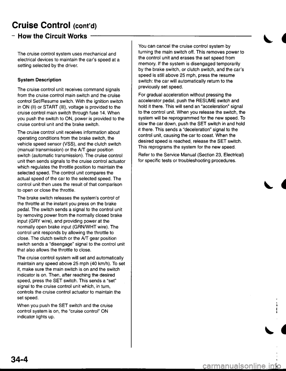
The cruise control system uses mechanical and
electrical devices to maintain the car's sDeed at a
setting selected by the driver.
System Description
The cruise control unit receives command signals
from the crurse control main switch and the cruise
control SeVResume switch. With the ignition switch
in ON (ll) or START (lll), voltage is provided to the
cruise control main switch through fuse 14. When
you push the switch to ON, power is provided to the
cruise control unit and the brake switch.
The cruise control unit receives information about
operating conditions from the brake switch, the
vehicle speed sensor (VSS), and the clutch switch
(manual transmission) or the A,/T gear position
switch (automatic transmission). The cruise control
unit then sends signals to the cruise control actuator
which regulates the throttle position to maintain the
selected speed. The conlrol unit compares the
actual speed of the car to the selected speed. The
control unit then uses the result of that comoarison
to open or close the throttle.
The brake switch releases the system's control of
the throttle at the instant you press on the brake
pedal. The switch sends a signal to the control unit
by removing power from the normally closed brake
input (GRY wire), and providing power at the
normally open brake input (GRN/vVHT wire). The
control unit responds by allowing the throttle to
close. The clutch switch or the A,/T gear position
switch sends a "disengage" signal to the control unit
that also allows the throttle to close.
The cruise control system will set and automatically
maintain any speed above 25 mph (40 km/h). To set
it, make sure the main switch is on and the switch
indicator is on. Then, after reaching the desired
speed, press the SET switch. This sends a "set"
signal to the cruise control unit which, in turn,
controls the cruise control actuator to maintain the
set speed.
When you push the SET switch and the cruise
control system is on, the "cruise control" ON
indicator lights up.
34-4
(
You can cancel the cruise control system by
turning the main switch off . This removes power to
the control unit and erases the set speed from
memory. lf the system is disengaged temporarily
by the brake switch, or clutch switch, and the car's
speed is still above 25 mph, press the resume
switch: the car will automatically return to the
previously set speed.
For gradual acceleration without pressing the
accelerator pedal, push the RESUME switch and
hold it there. This will send an "acceleration" signal
to the control unit. When you release the switch, the
system will be reprogrammed for the new speed. To
slow the car down. oush the SET switch in and hold
it there. This sends a "deceleration" signal to the
control unit, causing the car to coast. When the
desired speed is reached, release the SET switch.
This reprograms the system tor the new speed.
Refer to the Service Manual (Section 23, Electrical)
tor specific tests or troubleshooting procedures.
(
a
Page 1944 of 2189

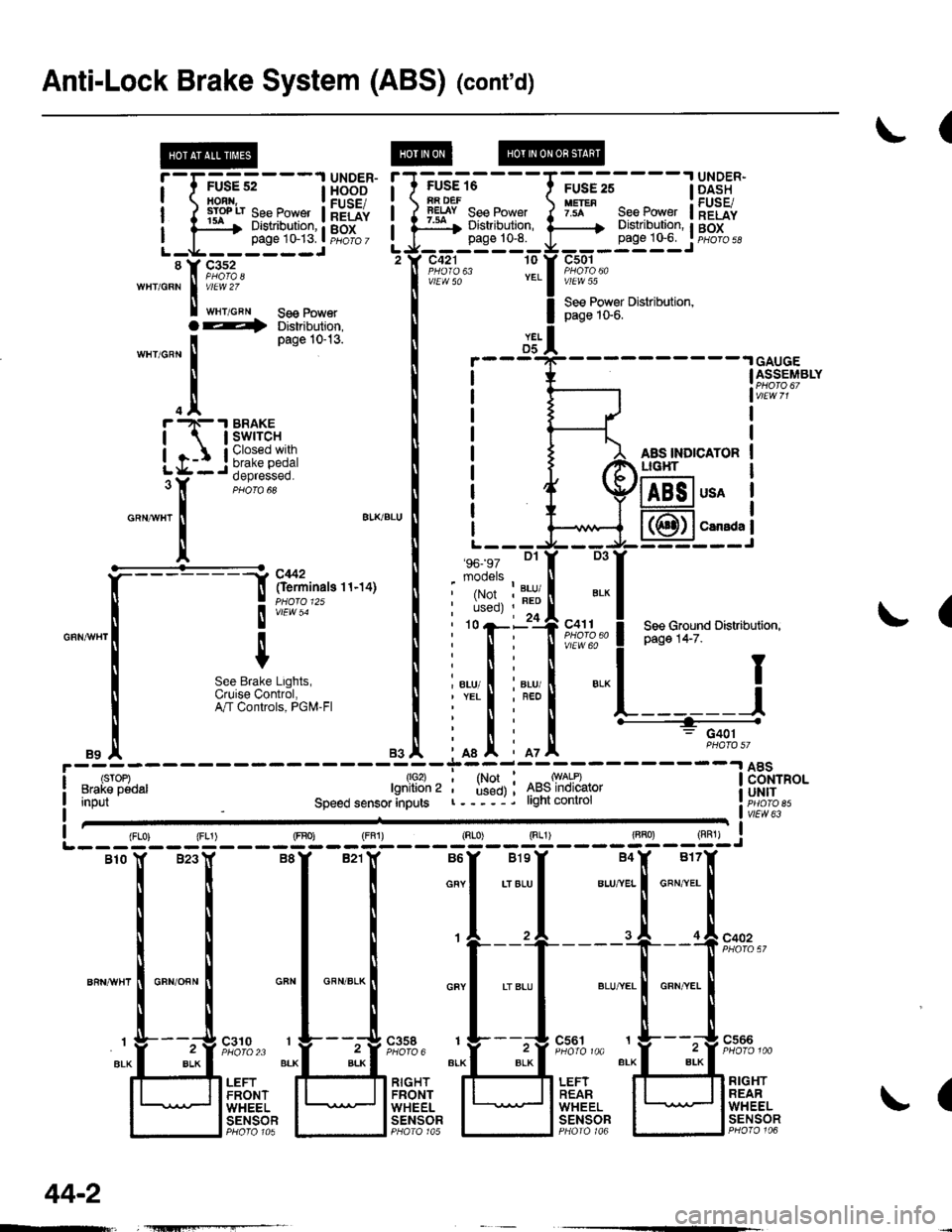
Anti-Lock Brake System (ABS) (cont'd)
(
FUSE 16iA DEFlEtsY See Power:ar Distribution,page 10-8.
c421 10
vlEW 50
'96- 97 Dl
mooels
.I UNDER-
page 1G6. I pHoro 5d
c501
vlEW 55
See Power Distribution,page 1S6.
AAS INDICATORLIG}IT
!'-r;us?;---l H5BE"
ilrryilrfi#ftilHriL-g------JL-g------J'tr F,1%'wHr/GRN I v/El.V 2Z
I t"r,o"" se€ Power
YELD5GAUGEASSEMBLY
usA
CarsdaI
(
D3
', ',i:,tr?""" ! P"g" t+-z".r',
*
! see cround Distributiofl,
".., I i"., I ".-l I;nl
iffit L------J
' n : G401
mI iot
T1*l ^*ry*l:-------l 8Bi"o.' used) ; 4ts5lnolcalor i UH|Tr----j. light conlrol r. iicib ett,"LTfflo",Input
1lo2)lgnition 2
Speed sensor anputsvlEw 63
(
{FLo) {FL1) (FBo) {FF1) (Rr"o) Sg____gT]-__g,l-j
Blo lf B23Y B8Y B21lf B6Y BlsY B4X B17f
i i I i o""l .,",-ul u.,"..1 o"",'.. I
rrttl
| | | I ,l ,l .I of"on"
ll ll I ti
't---'+----"[ --f !'?'%,'
""n*",lo"no""l *"1 *"*-l *"1 .'"."1 *,*.[ "**.I
I r L___t"" " t__t"." 1___!".""
"r.f_ "4::3' ;FJ,;::; ":f3:::1'' "lf-*i":''
t' ,.,Jtri"?r. ll;l]flffi lFli.ft. lU]flqtfl
l l"#tgl I lt5T8?l I lt"F"Ti?l I lt;Tt?f
O--t Distribution,
'n"r,o^n
I
Page 10-13'
.trr -N- .I BRAKE
| | swrrcH
igr:*
o"ntr"r
!
a'KBLU
It
""*[:-l
ftff^"n"o''''ot
I
", I
m;r""#,usi:",
".1
44-2
Page 1965 of 2189
Integrated Control Unit
NOTE: Fuse 31 is hot with lgnition Switch in START (lll) and clutch pedal depressed or A,/T Gear Selector in
PARK (P) or NEUTRAL (N), see Starting System, page 21,21-1, ot 21-2.
See BrakeSystemlndicatorli^hl
FUSE 3IstaaTEaSIGI{AT7AAI
I
I
I
I
I
\
\
\
\
\
\
I
I
I
I
I
I
/
S€s SiarlingSyslsm, pago 21,21-1. or 21'2.
SEs BrakeSystemlndicetorLight A6
SsaClharSrrESystom
Eog GoundDistlbution,page l,l-7.
L------3c420PHO|O 63vtEw 53
--r-r..r'
FED/BLU
SeeCeilingLightSee Seat Beltand lgnitionKey Remind€rs
t@
i'l-;;,-lH8B'r*| rrmn1gn I FUSEI
i f t*" ig8f"LJr____J PHOTO 7
u'lf tf,%,
S vtEw 3a
wHr/FED
| 3fl3,n'"n
wHr,FED I sYsteh
<--=- !t
,r"r,".0 | ,n"r,".u I
| .l B*?r:"" ,.!,.*,