Page 715 of 2189

TOROUE CONVERTER
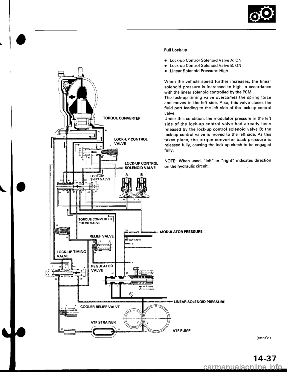
Full Lock-up
. Lock-up Control Solenoid Valve A: ON
. Lock-up Control Solenoid Valve B: ON
o Linear Solenoid Pressure: High
When the vehicle speed further increases. the linear
solenoid pressure is increased to high in accordance
with the linear solenoid controlled bv the PCM.
The lock-up timing valve overcomes the spring force
and moves to the left side. Also, this valve closes the
fluid port leading to the left side of the lock-up control
Under this condition. the modulator pressure in the left
side of the lock-up control valve had already been
released by the lock-up control solenoid valve B; the
lock-up control valve js moved to the left side. As this
takes place, the torque converter back pressure is
released fully. causing the lock-up clutch to be engaged
fully.
NOTE: When used, "|eft" or "right" indicates direction
on the hvdraulic circuit.
MODULATOR PRESSURE
LINEAR SOLENOIO PRESSURE
{cont'd)
LOCK.UP CONTROLSOLENOID VALVE
RELIEF VALVE
LOCK.UP TIMINGVALVE
'r ,-.r' cooLER RELTEF vALvE
ATF PUMP
14-37
Page 716 of 2189
Description
Lock-up System (cont'dl
TOROUE CONVERTER
Deceleration Lock-up
. Lock-up Control Solenoid Valve A: ON. Lock-up Control Solenoid Valve B: Duty Operation
OFF - ONa Linear Solenoid Pressure: Low
The PCM switches solenoid valve B on and off rapidly
under certain conditions. The slight lock-up and half
lock-up regions are maintained so as to lock the torque
converter properly.
NOTE: When used, "left" or "right" indicates direction
on the hydraulic circuit,
MOOULATOR PRESSURE
LINEAR SOLENOID PRESSURE
LOCK-UP CONTROLSOLENOID VALVE
RELIEF VALVE
LOCK.UP TIMINGVALVE
COOLER RELIEF VALVE
ATF STRAINER
1434
ATF PUMP
Page 717 of 2189
Component Locations
POWERTRAIN CONTROLMODULE (PCM)
TRANSAXLE {A/TI
COUNI€RSHAFTSPEED SENSOR
SOI,TNOID VALVEASSEMBLY
SOLENOID VALVEASSEMBLY
GEAR POSITION SWITCH
SPEED SENSOR
1+39
Page 719 of 2189
SERVICE CHECK CONNECTOR
LOCK -UP CONTROLSOLENOIO VALVEASSEMELY
RED WHT
tlll'
IT
tl
ll
Lo-l
MAINSHAFTSPEED SENSOR
TBRNiBLK
I
I
I-
G 101
NCSG ILS - ILS + ISH A ISH B ltc A ltc B
SHIF'CONTROLSOTENOID VALVEASSEMEI-Y
PCM Terminel Locations
14-41
Page 720 of 2189

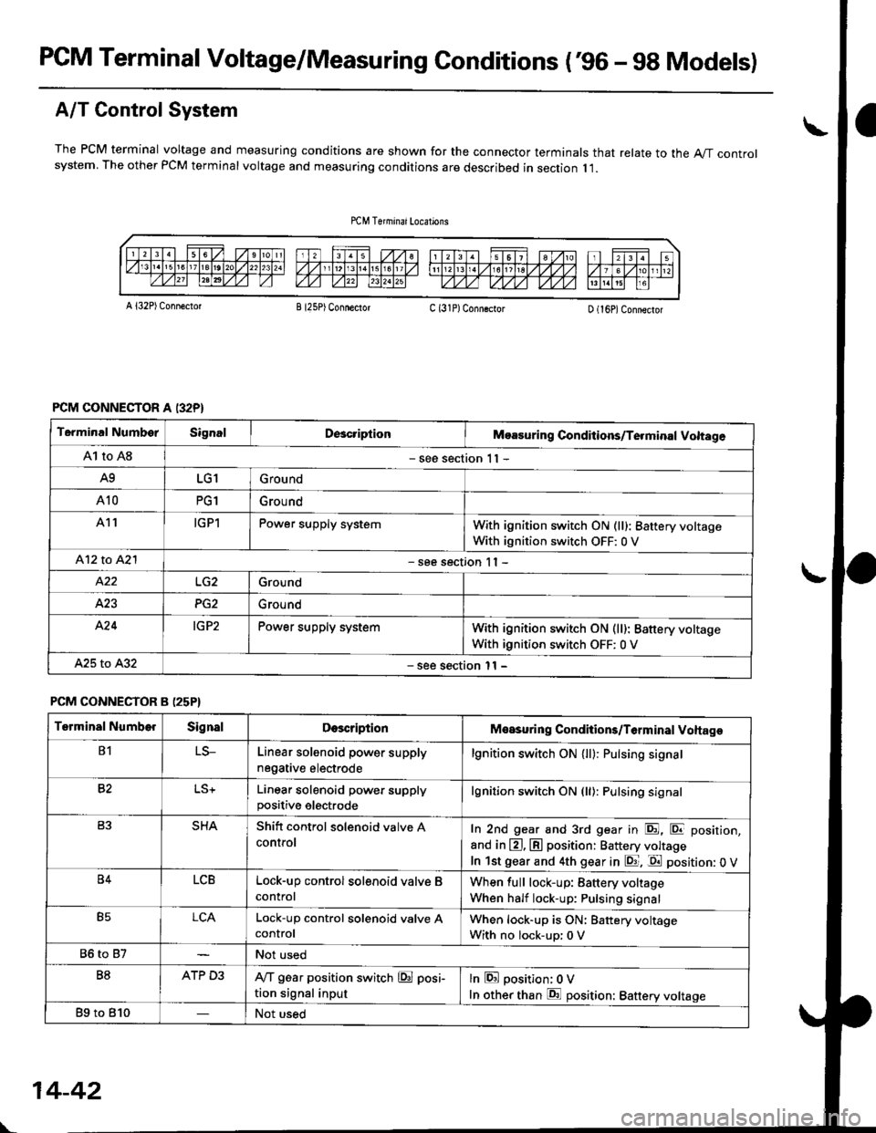
PCM Terminal Voltage/Measuring Gonditions ('96 - 9g Models)
A/T Control System
The PCM terminal voltage and measuring conditions are shown for the connector terminals that relate to the A"/T controlsystem. The other PCM terminal voltage and measuring conditions are described in section I l.
A l32P) Conn€ctotB I25P) ConnectorC (31P)ConngctorD (16P)Connector
PCM CONNECTOR A I32P}
Terminal NumborSignalDcacriptionMoasuring Conditions/Te.minal Voltage
A1 to A8- see section 1 I -
A9LG1Ground
A10PG1Grou nd
A11IGPlPower supply systemWith ignition switch ON (ll): 8attery voltage
With ignition switch OFF: 0 V
412 to A2l- see section I I -
Ground
423PG2Ground
A'24IG P2Power supply systemWith ignition switch ON (ll): Battery voltage
With ignition switch OFF: 0 V
A25 to A32- see section l1 -
PCM CONNECTOR B (25P}
Terminal NumberSignalDescriptionMeasuring Conditions/T6rminal Voltage
B1LS-Linear solenoid power supply
negative electrode
lgnition switch ON (ll): Pulsing signa.
82Linear solenoid power supplypositive electrode
lgnition switch ON (ll): Pulsing signal
SHAShitt control solenoid valve A
controlIn 2nd gear and 3rd gear in E, E position,
and in @, @ position: Battery voltage
In lst gear and 4th gear in E. E position: 0 V
B4LCBLock-up control solenoid valve B
control
When full lock-up: Battery voltage
When half lock-up: Pulsing signal
B5LCALock-up control sol€noid valve AcontrolWhen lock-up is ON: Battery voltage
With no lock-up: 0 V
86 to 87Not used
B8ATP D3IVT g6ar position switch @ posi-
tion signal input
lnEposition; OV
In other than E position: Battery voltage
Bg to 810Not used
\-
14-42
Page 721 of 2189

I
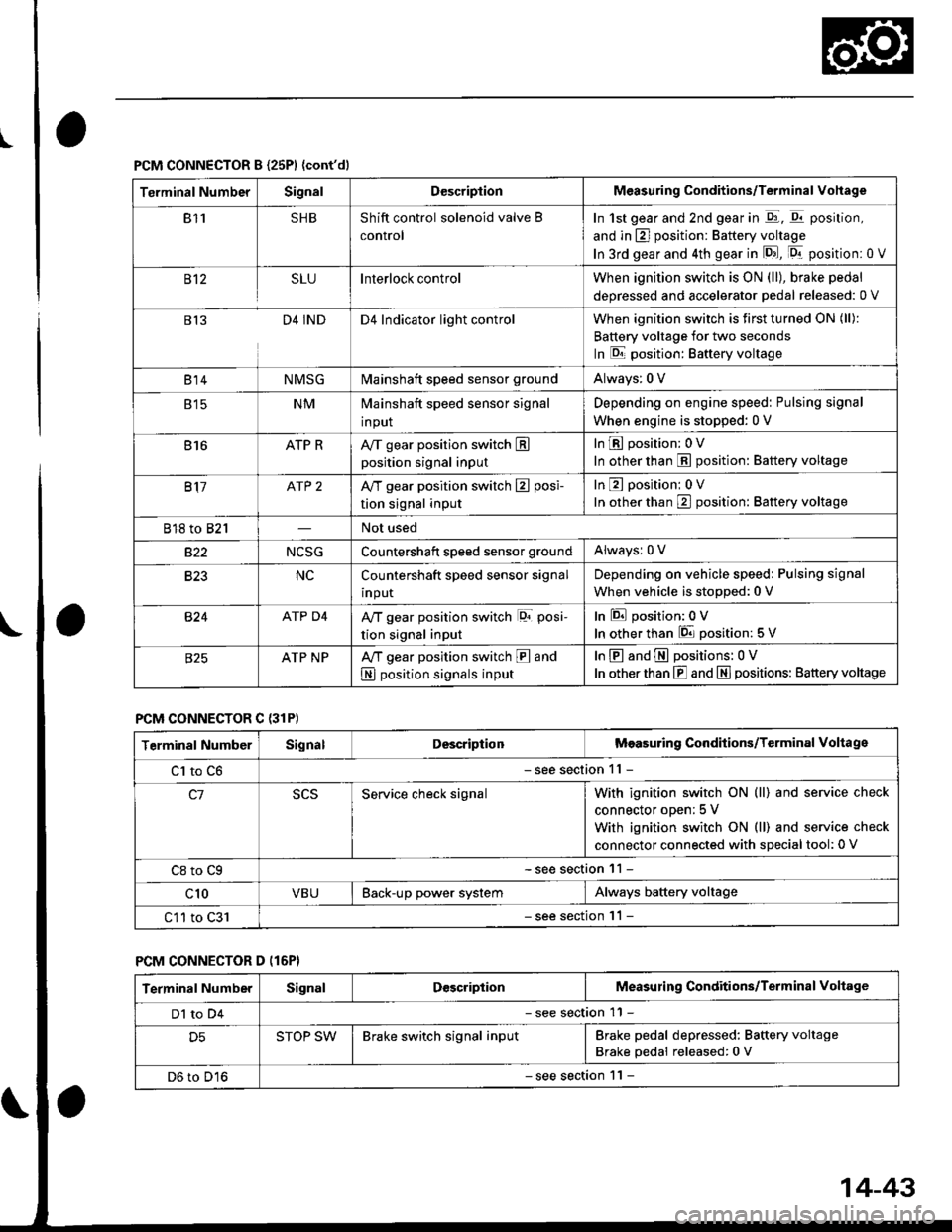
PCM CONNECTOR B {25P1 {cont'dl
Terminal NumberSignalDescriptionMeasuring Conditions/Terminal Vohage
811SHBShift control solenoid valve B
control
In 1st gear and 2nd gear in -q1, q11 position,
and in E] position: Battery voltage
In 3rd gear and 4th gear in lD.J, [Dr- position: 0 V
B't2SLUInterlock controlWhen ignition switch is ON (ll), brake pedal
deoressed and accelerator Dedal released: 0 V
813D4 INDD4 Indicator light controlWhen ignition switch is first turned ON (ll):
Battery voltage for two seconds
In E position: Baftery voltage
B't 4NMSGMainshaft speed sensor groundAlways: 0 V
E tcNMMainshaft speed sensor signal
input
Depending on engine speed: Pulsing signal
When engine is stopped: 0 V
816ATP RAy'T gear position switch Eposition signal input
InE position: 0V
In other than E position: Battery voltage
817ATP 2A/T gear position switch E posi-
tion signal input
InE position: 0V
In orher than E position: Battery voltage
818 to 821Not used
s22NCSGCountershatt speed sensor groundAlwaysr 0 V
B�23NCCountershaft speed sensor signal
input
Depending on vehicle speed: Pulsing signal
When vehicle is stopped: 0 V
B�24ATP D4Ay'T gear position switch lor posi-
tion signal input
InEposition:0V
In other than 6 position: 5 V
ATP NPA,/T gear position switch E and
N position signals input
InE and E positions: 0V
In otherthan E and N] positions: Battery voltage
PCM CONNECTOR C {31P)
Terminal NumberSignalDescriptionMeasuring Conditions/Terminal Voltage
Cl to C6- see section 11 -
c1Service check signalWith ignition switch ON (ll) and service check
connector oDen; 5 V
With ignition switch ON (ll) and service check
connector connected with sDecial tool: 0 V
C8 to Cg- see section 11 -
c10VBUBack-up power systemAlways battery voltage
C11 to C31- see section '11 -
PCM CONNECTOR D (16P}
Terminal NumberSignalDescriptionMeasuring Conditions/Terminal Voltage
Dl to D4- see section 11 -
D5STOP SWBrake switch signal inputBrake pedal depressed: Battery voltage
Brake pedal released: 0 V
D6 to D16- see section 1 l -
14-43
Page 722 of 2189
PCM Gircuit Diagram (A/T Gontrol System:'99 - 00 Models)
UNOEF DASIFL]SE/FELAY BOX
ta T06 T Dr.
INT€RLOCKCCNTFOLuN|l
ert*rll
I STARTEF
r-->lIl__ sL!
I
UISEF,DASHFISSIEL YmXr,Jo 25 (7 5A) GAUGE ISSEMBLY
Lr GRN -----l l"-- LTGRll
L eultru ----iF erk€Lu
14-44
Page 724 of 2189

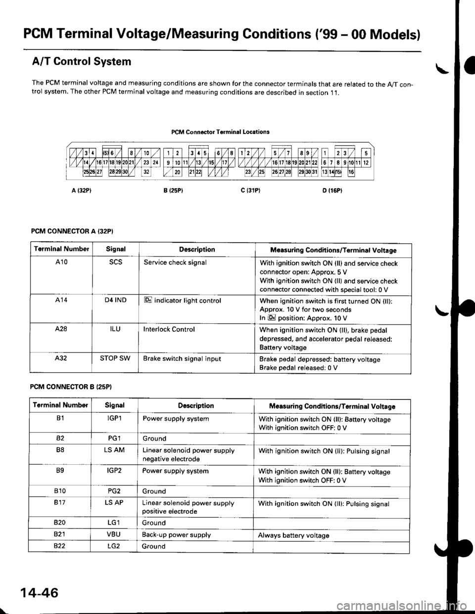
PCM Terminal Voltage/Measuring Conditions ('99 - 00 Models)
A/T Control System
The PCM terminal voltage and measuring condjtions are shown for the connector terminals that are related to the A//T con-trol system, The other PCM terminal voltage and measuring conditions are described in section ,11.
PCM Connoctor Tgrminrl Locations
PCM CONNECTOR A {32PI
PCM CONNECTOR 8 (25P}
Terminal NumbelSignalDescriptionM€asuring Conditions/Terminal Voltage
A105L5Service check signalWith ignition switch ON (ll) and service check
connector open: Approx, 5 V
With ignition switch ON (ll) and service check
connector connected with sDecial tool: 0 V
A14D4 INDE indicator light controlWhen ignition switch is first turned ON (ll):
ApDrox. 10 V for two seconds
In E position: Approx. 1O V
428ILUInterlock ControlWhen ignition switch ON (ll), brake pedal
depressed, and accelerator pedal rereaseo:
Battery voltage
A.32STOP SWBrake switch signal inputBrake pedal depressed: battery voltage
Brake oedal released:0 V
Terminal NumberSignalDescdptionMeasuring Condhions/Torminal Voltag6
B1!GP1Power supply systemWith ignition switch ON (ll): Battery voltage
With ignition switch OFF: 0 V
PGlGround
B8LS AMLinear solenoid power supply
negative electrode
With ignition switch ON (ll): Pulsing signal
B9IG P2Power supply systemWith ignition switch ON (ll): Baftery voltage
With ignition switch OFF: 0 V
810PG2G rou nd
917LS APLinear solenoid power supplypositive electrode
With ignition switch ON (ll): Pulsing signal
B�20Ground
VBUBack-up power supplyAlways battery voltage
822Ground
\
14-46