1996 HONDA CIVIC moonroof
[x] Cancel search: moonroofPage 1295 of 2189
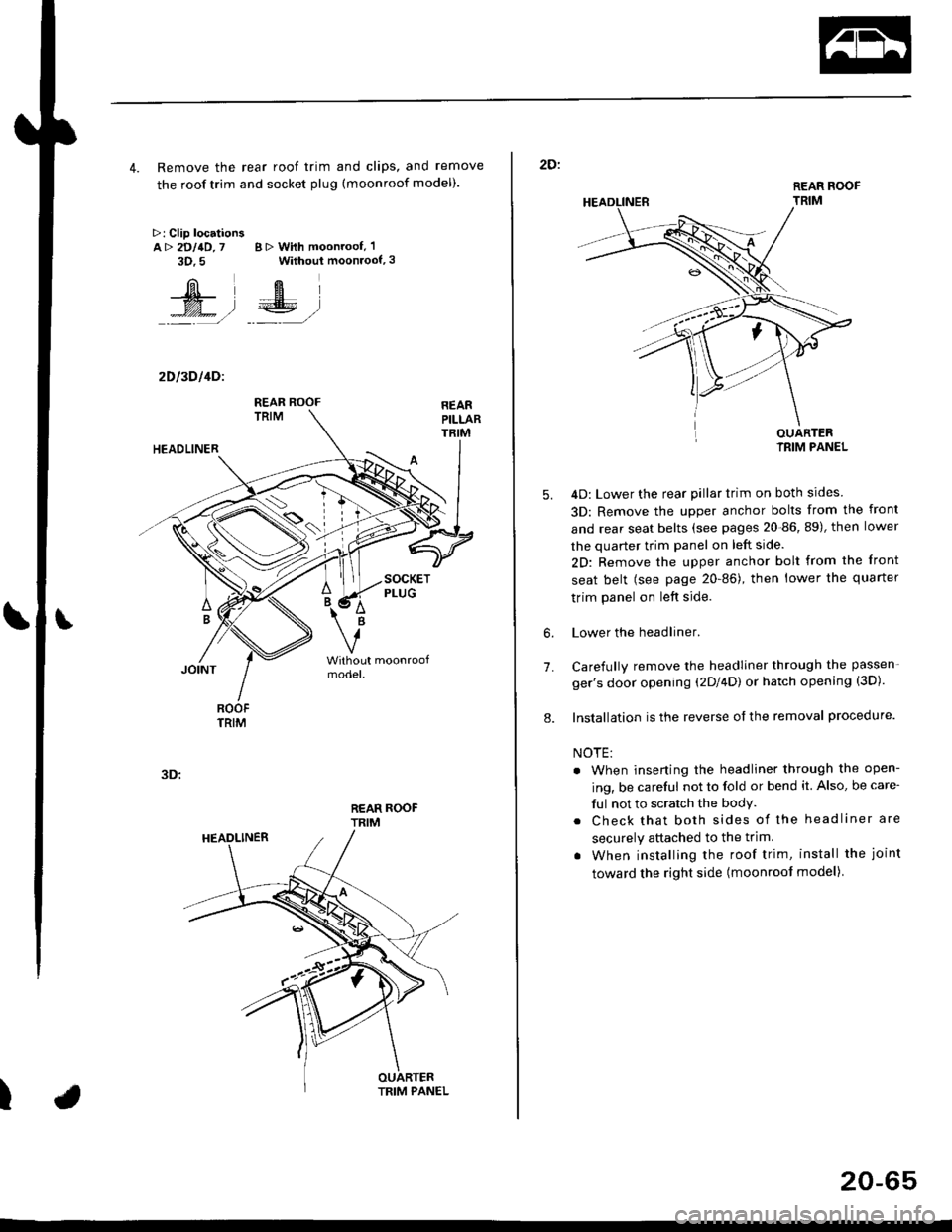
4. Remove the rear roof trim and clips, and remove
the roof trim and socket plug (moonroof model).
>: Clip locationsA> 2DllD,7 B > With moonroof, 'l
3D.5 Without moonroof,3
[il',fEl
t% .l €E .l':: =,/ _._- ,/
2D l3D l4Dl
REAR ROOFTRIM
3D:
t
REAR ROOF
TRIM
2D:
5.
7.
OUARTERIRIM PANEL
4D: Lower the rear pillar trim on both sides
3D: Remove the upper anchor bolts from the front
and rear seat belts (see pages 20-86, 89), then lower
the quarter trim panel on left side.
2D: Remove the upper anchor bolt from the front
seat belt (see page 20-86), then lower the quaner
trim panel on left side.
Lower the headliner.
Carefully remove the headliner through the passen-
ger's door opening (2Dl4D) or hatch opening (3D).
Installation is the reverse of the removal procedure.
NOTE:
. When inserting the headliner through the open-
ing, be careful not to fold or bend it. Also, be care-
ful not to scratch the bodY.
. Check that both sides of the headliner are
securely attached to the trim.
. When installing the roof trim, install the joint
toward the right side (moonroot model)
6.
8.
20-65
Page 1298 of 2189
Dashboard
Component RemovaUlnstallation
CAUTION: When prying with a flat-tip screwdriver,
wrap it with protoctivo tape, and apply protective tape
around tho r6lat6d parts, to prevent damag6.
NOTE: Take care not to scratch the dashboard and relatedpans.
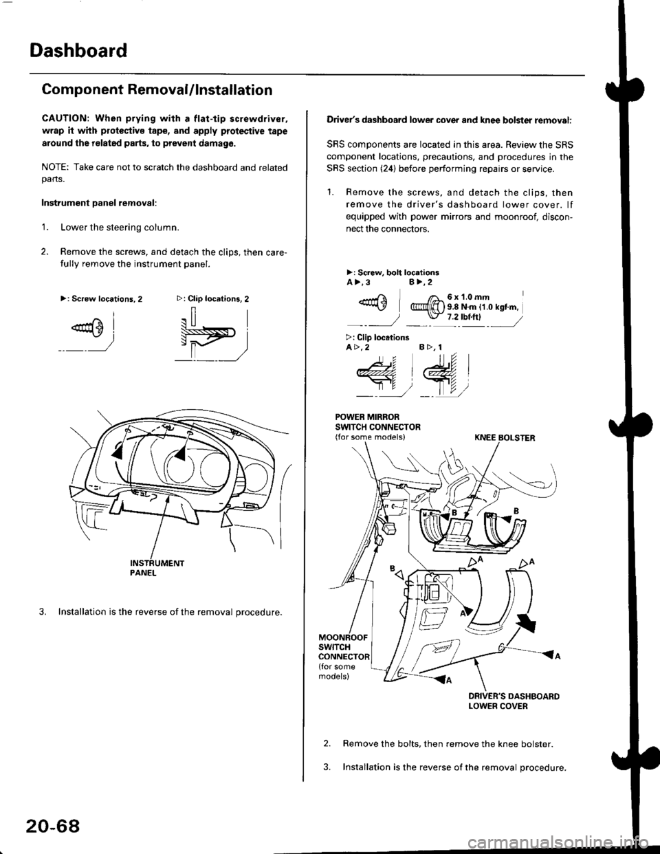
Instrument Danel removal:
1.Lower the steering column.
Remove the screws, and detach the clips, then care-
fully remove the instrument panel.
3. Installation is the reverse of the removal procedure.
>: Clip locations, 2
.il |
Pit)_ _ ,/
>: Screw locations,2
^l
@sl
:)
PANEL
20-68
Driver's dashboard lower cover and knee bolster removal:
SRS components are located in this area. Review the SRS
component locations, precautions. and procedures in the
SRS section (24) before performing repairs or service.
'1. Remove the screws, and detach the clips, then
remove the driver's dashboard lower cover. lf
equipped with power mirrors and moonroof, discon-
nect the connectors.
>: Screw, boh loc.tionsA>.3B>,2
_-rri I /a_6x1.0mm*\Y @{[) s 8 N'm tt o rst'm,
_-_- J _ \J- 7 2_rbtftl -_
>: Clip locationsA>.2 B >, 1
tu
DRIVER'S DASHBOARDLOWER COVER
Remove the bolts, then remove the knee bolster.
Installation is the reverse of the removal procedure.
Page 1300 of 2189
Dashboard
Gomponent Removal/lnstallation
(cont'd)
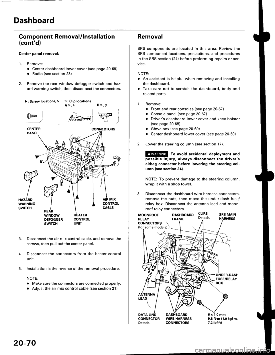
Center panel removal:
1. Remove:
. Center dashboard lower cover (see page 20-69)
. Radio {see section 23)
2. Remove the rear window defogger switch and haz-
ard warning switch, then disconnect the connectors.
>: Screw locations, 5 >: Clip locationsA>,4 B>,3
fii*-)
CENTERPANEI.
rt-xR.
W
IHAZARDWARNINGswlTcH
r44 "
F.IZvl
IIREARwtNoowOEFOGGERswtrcH
MtxCONTNOLCABLE
3. Disconnect the air mix control cable, and remove the
screws, then pull out the center panel.
4. Disconnect the connectors from the heater control
u nit.
5. Installation is the reverse of the removal procedure.
NOTE:
. Make sure the connectors are connected properly.
. Adjust the air mix control cable (see section 21).
20-70
Removal
SRS components are located in this area. Review the
SRS component locations, precautions, and procedures
in the SRS section (24) before preforming repairs or ser-
vice.
NOTE:
. An assistant is helpful when removing and installing
the dashboard.
. Take care not to scratch the dashboard, body and
related parts.
1. Remove:
o Front and rear consoles (see page 20-67)
. Console panel (see page 2O 67),
. Driver's dashboard lower cover and knee bolster(see page 20-68)
. Glove box (see page 20-69)
. Center dashboard lower cover (see page 20-69i
2. Lower the steering column (see section 17).
@ To avoid accidental deplovment and
possible injury, always disconnect the driver's
airbag connector belore lowering the steering col-
umn lsee section 241.
NOTE: To prevent damage to the steering column,
wrap it with a shop towel.
3. Disconnect the dashboard wire harness connectors,
remove the nuts, then move the under-dash fuse/
relay box. Disconnect the antenna lead and moon-
roof relay connectors.
DASHBOARD cltPs
CONNECTORS(for some models)
MOONROOFRELAY
ANTENNALEAO
FRAME
SRS MAINHARNESS
9.8 N.m (1.0 kgf m,7.2lbt.ltl
DATACONNECTOR WIRE HARNESSDetach. CONNECTORS
Page 1471 of 2189

l'f .
Electrical
Special Toofs .,....................,23-2
Troubleshooting
Tips and Precautions ..............,.................... . 23-3
Five-step Troubleshooting .............. ......... . . 23-5
wire color codes ..........,23-5
Schematic Symbols ........,................... . . .. .... 23-6
Relay and Control Unit Locations
Engine Compartment ...,..................... ... .. . 23'7
Dashboard ......................23-8
Dashboard/Door ......... 23-12*Airbags ................. ....... Section 24
Air Conditioning ......... Section 21
Aftelnator ..........."""" """ 23-112
Anti-lock Brake System {ABS) Section 19*A/T Gear Position Indicator .....................,. .... ... 23-149
Automatic Transmission Svstem .... . ....... Section 14
Batterv ......... . . . ... ...... .......23-91
Blower controls .. . ... Section 2l
Charging System ....'...........23'112
Connector ldentilication and Wire Harness
Routing .................. ......23'13
Cruise Control ............,........23-240
Dash Lights Brightness Controller ............. ....... 23-180
Fan controfs "" 23'126
Fuel PumD ........ . ........ section 11
Fuses/Refay ...............,..,,.. 23'62
PGM-FI Control System ......................,....... Section 1 1
*Gauges
Circuit Diagram ....,.,.......23-131
Fuef Gauge ...........'.'.......23-142
Gauge/lndicator .. . .. 23-129
Ground Distribution .. . 23-75
Heatei controls .. . ..... Section 21*Horn................. ...............23-196
*tgnition Switch ....................23-89
lgnition System .......,.... 23-102
*lntegrated Control Unit ....................................... 23-156
fnterlock System ,........ . . , ,23-144
Lighting System . . . .. ......... 23-161
Lights, Exterior
Back-up Lights ..'............23'171
Brake Lights .................. 23'174
Daytime Bunning Lights (Canadal ............... 23'166
Front Parking Lights ......,................ .'. .......... 23-167
Front Turn Signal Lights .......... . . ............ ..,.23-167
Headtights ....".'....-... ..... 23'167
High Mount Brake Light ...................... ... .23'179
License Plate Lights ...... 23'176
Taitfights ................ .......23'171
lnterior Lights ..-.......,, . 23-142
Moonroof ..,.................,........ 23-235
Power Distribution ....... . . .23-61
Power Door Locks .......,,,. .23'251
Power Mirrors ,..............,.,...23'206
Power Relays ....... . ...... . . .. 23-86
Power Windows ............,,....23-220
Rear Window Defogger .......................... . . ... . . 23-2OO
Spark Plugs . ..... . ........ .....23-111
Slarting System ................23-93*stereo Sound Svstem ,................. ..... ... . ... ,.,.,,23'147'Supplemental Restraint System (SRS) ... . Section 24
Turn Signal/Hazard Flasher System .......'.'....-... 23-173
*Undel-dash Fuse/Relay Box ............,.................. 23-85
vehicfe soeed sensor (VSSI """" ""' 23-140+Wipers/Washers .........,.,.,...23-214
NOTE: Unless otherwise specified, references to auto-
matic transmission (Mf) in this section include the CVT.
Page 1478 of 2189
Relay and Control Unit Locations
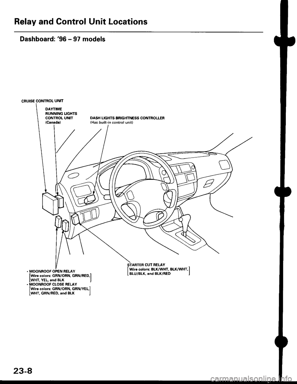
Dashboard: '96 - 97 models
CRUISE CONINOL UNIT
DAYTIMERUNNING LIG}ITSCONTROL UNITlCan!dal
IWire colo.s: GRN/ORN, GRN/RED,l
IWHT, YEL, and BLK I. MOONROOF CLOSE RELAYfwir. colorc: GRN/ORru, Cnru/VeLl
IWHT. GRN/RED, and ALK I
DASH LIGHTS BRIGHTNESS CONTROLLER{Has built-in control unit)
23-8
Page 1480 of 2189
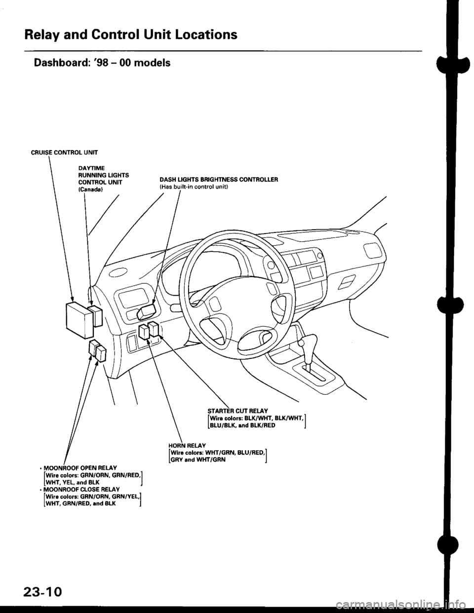
Relay and Control Unit Locations
Dashboard: '98 - 00 models
CRUISE CONTROL UNIT
DAYTIMERUNNING LIGIfiSCONTROL UNITlCrnrda)
DASH LIGHTS BRIGHTNESS CONTROLLER{Has built-in control unit}
STARTEB CUI RELAY
[wi]e color.: BLX/WHT, exnfxf, IIBLU/BLK, |nd BLK/RED j
coloE: WHT/GRN, BLU/REO,IandWHT/GRN I
MOONROOF CLOSE RELAY
fwiro colors: GRN/O8ru. CnrulYel,l
IWHT, GBN/RED, end BLK I
23-10
Page 1483 of 2189
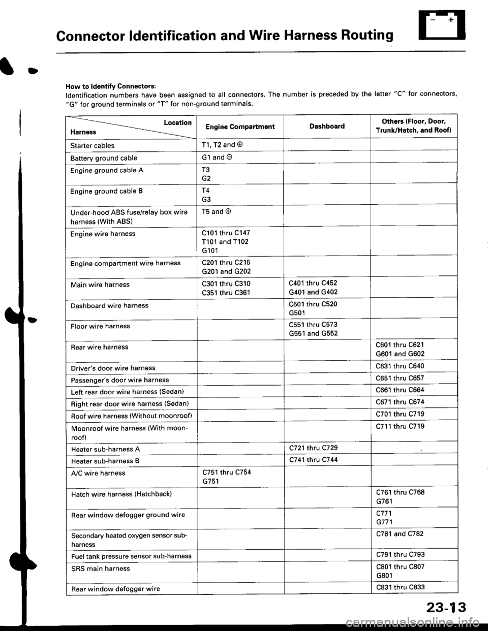
Connector ldentification and Wire Harness Routing
D
How to ldentify Connectors:
ldentification numbers have been assigned to all connectors. The number is preceded by the letter "C" for connectors,"G" for ground terminals or "T" for non-ground terminals.
Location
HarnessEngine CompartmentDashboardOthers {Floor, Door,
Trunk/Hatch, and Rootl
Starter cablesT1, T2 and @
Battery ground cableG1 and O
Engine ground cable AT3
G2
Engine ground cable BT4
Under-hood ABS fuse/relay box wire
harness (With ABS)
t5 ano (9
Engine wire harnessCl01 thru C147
T101 and T102
G101
Engine compartmenl ware harnessC201 thru C215
G201 and G202
Main wire harnessC301 thru C310
C351 thru C361
C401 thru C452
G401 and G402
Dashboard wire harnessC501 thru C520
G501
FIoor wire harnessC551 thru C573
G551 and G552
Rear wire harnessC601 thru C62l
G601 and G602
Driver's door wire harnessC631 thru C640
Passenger's door wire harnessC651 thru C657
Left rear door wire harness (Sedan)C661 thru C664
Right rear door wire harness (Sedan)C671 thru C674
Roof wire harness (Without moonroof)C701 thru C719
Moonroof wire harness {With moon-
roof)
C7l'l thru C719
Heater sub-harness AC721 thru C729
Heater sub-harness BC7 41 thtu C7 44
Ay'C wire harnessC751 thru C754
G751
Hatch wire harness (Hatchback)C761 thru C768
Rear window defogger grgund wirec771
G171
Secondary heated orygen sensor sub-
narness
C781 and C782
Fuel tank pressure sensor sub-harnessC791 thru C793
SRS main harnessC801 thru C807
G801
Rear window defogger wireC831 thru C833
Page 1502 of 2189
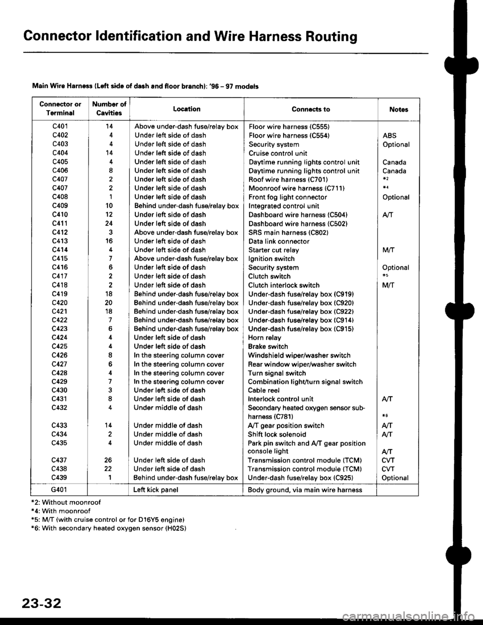
Connector ldentification and Wire Harness Routing
Connector or
Terminal
Number of
CavhiosLocationConnocts ioNotes
c401
c402
c403
c404
c405
c406
c407
c407
c408
c409
c410
c411
c412
c413
c414
c415
c416
c417
c418
c4l9
c420
c42'l
c423
c424
c425
c426
c427
c42A
c429
c430
c431
c432
c433
c434
c435
c431
c438
c439
'14
't4
I
I
10't2
24
16
7
o
18
20
18
7
6
I
o
4
7
8
14
1
Above under-dash fuss/relay box
Under left side ot dash
Under left sid€ of dash
Under left side of dash
Under left side of dash
Und€r left side of dash
Under left side of dash
Under left side of dash
Under left side of dash
Behind under-dash fuse/relay box
Under left side of dash
Under left side of dash
Above under-dash fuse/relay box
Under left side of dash
Under left side of dash
Above under-dash fuse/r€lay box
Under left side of dash
Under left side of dash
Under left side of dash
Behind under-dash fuse/relay box
Eehind under-dash fuse/relay box
Behind under-dash fuse/relay box
Behind under-dash fuse/relay box
Behind under-dash fuse/relay box
Under left side of dash
Under left side of dash
In the steering column cover
In the steering column cover
In the steering column cover
In the steering column covEr
Under left side of dash
Under left side of dash
Under middle of dash
Under middle of dash
Under middle of dash
Under middle of dash
Under left side of dash
Under left side of dash
Eehind under-dash fus€/relay box
Floo. wire harness (C555)
Floor wire harness (C554)
Security system
Cruise control unit
Daytime running lights control unit
Daytime running lights control unit
Roof wire harness (C701)
Moonroof wire harness (C7l1)
Front fog light connector
Integrated control unit
Dashboard wire harness (C504)
Dashboard wire harness (C502)
SRS main harness (C802)
Data link connector
Starter cut relay
lgnition switch
Security system
Clutch switch
Clutch interlock switch
Under-dash fuss/relay box (C9191
Undor-dash fuse/r€lay box {C920)
Under-dash tuse/relay box (C922)
Under-dash luse/relay box (C914)
Under-dash fuse/rBlay box (C915)
Horn relay
Brake swilch
Windshield wiper/washer switch
Rear window wiper/washer switch
Turn signal switch
Combination lighvturn signal switch
Cable reel
lnterlock control unit
Secondary heated oxygen sensor sub-
harn€ss (C781)
Ay'T gear position switch
Shift lock solenoid
Park pin switch and Ay'T gear position
console light
Transmission control module (TCM)
Transmission control module {TCM)
Under-dash fuse/relay box {C925)
ABS
Optional
Canada
Canada
Optional
Atr
MTT
Optional
Mlf
NT
Atf
CVT
CVT
Optional
AN
Atr
G401Left kick panelBody ground, via main wire harness
Main Wir€ Harness (Loft side of da3h and floor branch): '96 - 97 models
*2:Without moonroof*4: With moonroof*5: M/T (with cruise control or for D16Y5 engine)*6: With secondary heated oxygen sensor (H02S)
23-32