Page 1550 of 2189

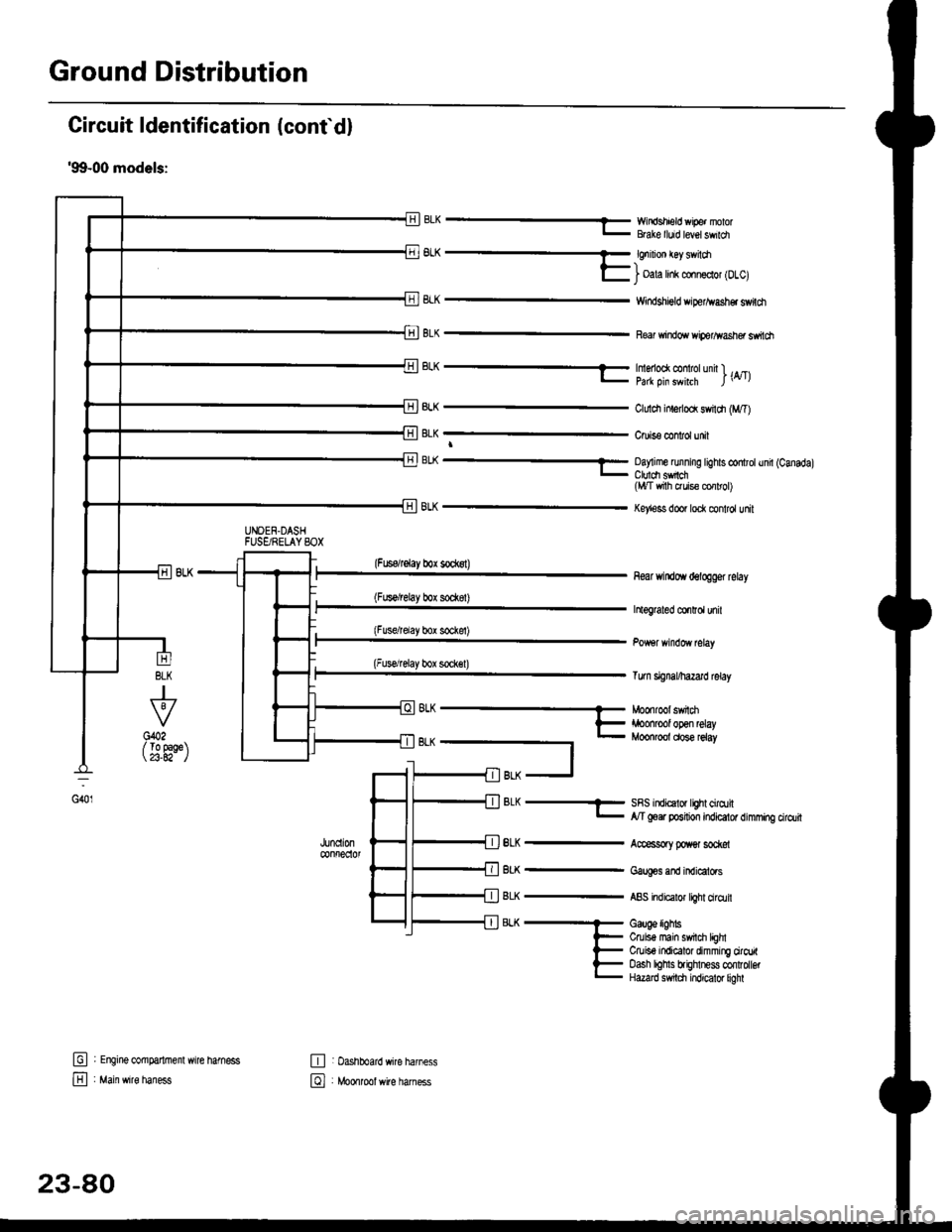
Ground Distribution
Circuit ldentification (conf d)
'99-00 models:
EWir'rdshield wipe. nolorBGke lluid level swildl
6L^ -- €nrnon €y sv loa-)l- i oala hnk conn€clol lDlcl
8LK
BLK
Windshigld dper^vash€r switdt
Re windo wiperlflasher ssitch
BLK
J
To 9aqe23.A2-
tr
E
UNOEN.DASHFUSgRELAYSOX
-r^ -..-- tmenoo( @ rotunn l ._.l- pa* oin swhrh l\4tl
ClLrldr inlerlod swildr (M,T)
Cruis€ confol unit
BL( ---- Oay me running tights controtund (Canadal_ Ctuldt sfich(l,t/T vrith ruis€ cor rol)
Key'ess door lock control unit
(Fuserelay box sockst)
(Fus€/relay box sod(8t)
(Fusdrelay bor sockel)
(Fuserelay box sock€l)
8LK
BLK
BLK
BLK
8LK
near windoYr delogger rclay
htograted co.Ird unil
Tum signal/hazard lelay
SRS indicalor lighl cirqtil,y'T goer position indicator dimming cirdlit
Accessory poxer sod@l
Gaug€s and indicators
ABS indicalor light ciro.lil
Gauge lighbCruis€ main swil$ lEhlCruiso indicator dimming ciroritoash lohls brighlness confolbtHazard s$tdl indicator liohl
G401
(
oh --- Moonroot swnm
t- iroonrool open relay- Moonroot dose reiay
t
fil BLK -J
: Engine @mparlrnenl wire hamess
: Main wire haness
,JUncll0n@nfreclol
E : Dashboard wire harness
El , Mo*tool *ite har"..
23-80
Page 1621 of 2189
JCircuit Diagram
A/TUNDER HCCD FUSE BELAY BOX
PCi\4
V
I
I.T Gq
GNIT ONSW TCHTJNDEF OASH
'^a" fr-.-r^ """- *
-l
6l\
U__t- -t ir_i ;_P _+irh-
\:f
; h,:_
ArT GEAR POS TION IND CATOF (n lhegauge assembyl
A13412
YEL
f333{'*)
f7
IRED,ELKPCM
V
IGRNlBLK
I
l-
6LK 8LU
12
f7 f7 fl
ItlWHT YEL GFN
rl\4 l765 2 (Nol used)
{'}'}'1,
I
A._. --An i
t.--it-
Lrl9_PNK-
A'T GEARBLK
AIT GEAR POSTON NDLCA1ORD MM]NG CIRCUT
II
I
DASH L GHTSBRIGHTNESSCONTFOLLER
f7
ISLU\. -Ti i:5AFL]SE
V
IF:I BLK
I
l',
ll^,.,^,1L,-N pos r oN II(d].ONSCLEI
lYi:il |
Il--f'-
IRED
I
I
DASH L GHTSBB GHTNESSCONTFOLLER
BLK
I
oio,G402
23-151
Page 1743 of 2189

Description
)
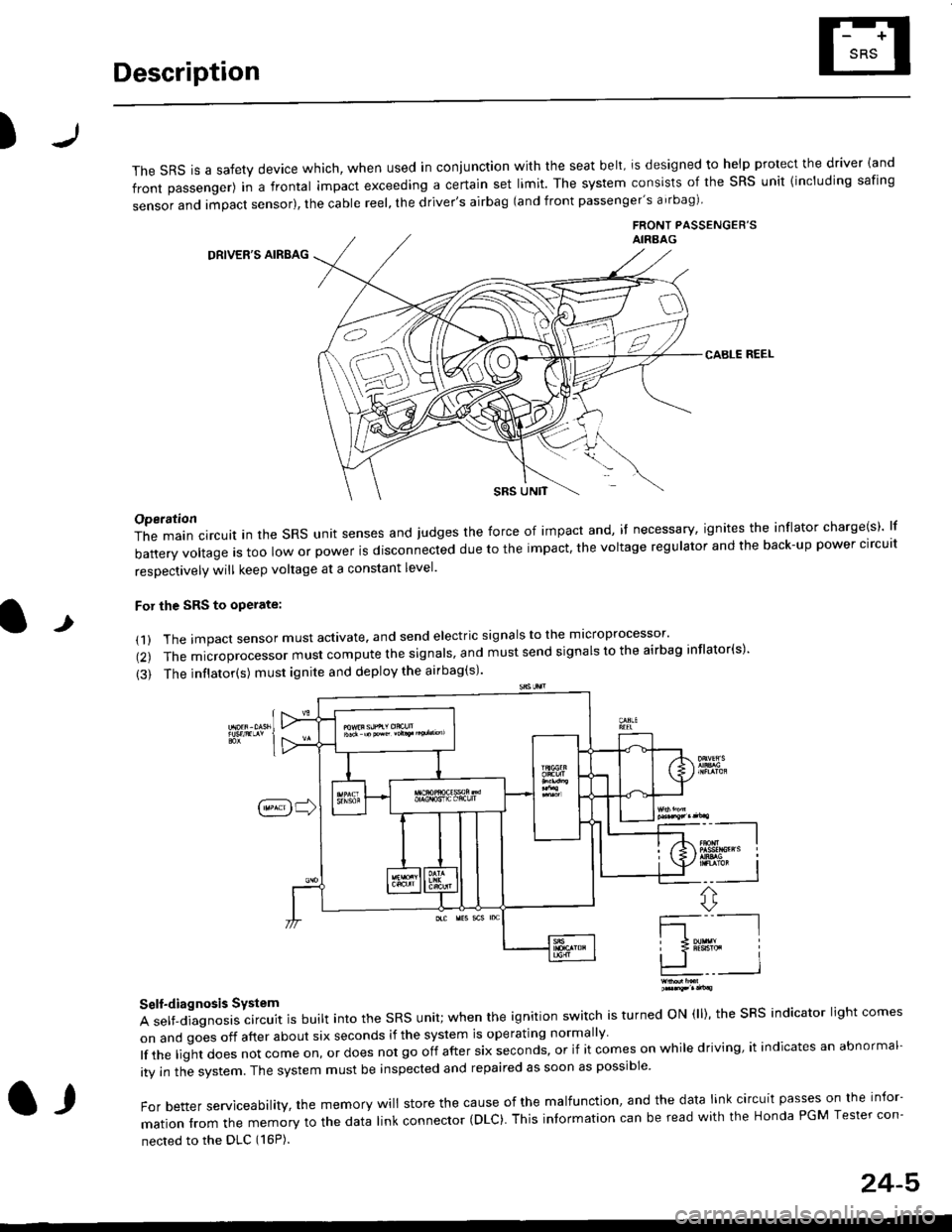
The sRS is a safety device which, when used in coniunction with the seat belt, is designed to help protect the driver land
front passenger) in a frontal impact exceeding a certain set limit. The system consists of the sRS unit {including safing
sensor and impact sensor), the cable reel, the driver's airbag (and front passenger's airbag)
FRONT PASSENGEB'SAIRAAG
DRIVER'S AIRBAG
CABLE REEL
SRS UNtT
t
Operation
The main circuit in the SRS unit senses and judges the force of impact and, if necessary, ignites the inflator charge(s) lf
battery voltage is too low or power is disconnected due to the impact, the voltage regulator and the back-up power clrcult
resoectivelv will keep voltage at a constant level.
For the SRS to operate:
(1) The impact sensor must activate. and send electric signals to the mlcroprocessor'
(2) The microprocessor must compute the signals' and must send signals to the airbag inflator(s)'
{3) The inflator(s) must ignite and deploy the airbag(s)'
_"-_-l
Ir3B!#h i
!.. I
ffi,*
Self-diagnosis System
A self-diagnosis circuit is built into the SRS unit; when the ignition switch is turned ON (ll), the SRS indicator light comes
on and goes off after about six seconds if the system is operating normally
lf the liglt does not come on, or does not go off after six seconds, or if it comes on while driving, it indicates an abnormal-
ity in the system. The system must be inspected and repaired as soon as possible
For better serviceability, the memory will store the cause of the malfunctlon, and the data link circuit passes on the infor-
mation from the memory to the data link connector (DLC). This intormation can be read with the Honda PGM Tesler con-
nected to the DLC (16P).
l,
24-5
Page 1744 of 2189
Circuit Diagram
UNDER-HOOD FUSE/RELAY 8OXIGNITIONSWITCH
WHT/8LI( +WHT
Brake systsm light
passenger's airbag
l----ltlI DUMMY II BESISTOR I
tll
tl
la rl
MEMORY ERASESIGNAT IMES)CONNECTOR I2P)
GRY{GRN)
I
BRN BRN
tl.-l- .-r-\./ \./
ECM/PCM SERVICECHECKCONNECTOR
ILT 8LU
I
t'7
DATA LINKCONNECTOR{DLC) {r6P)
GRY GRY(GRN) IGNN)
V:
G801
Teminalside oi thal€ terminals
24-6
4''
SRS UNIT TERMINALSG40tG402
SBS INDICATOR CIRCUIT{ln the gauge assembly)
PGM_FI
DRIVER'SAIRBAGINFLATOR
10 14 r 13 6 7(VAl 3{VBlSRS UNIT16 17 t5 9 18 8
Page 1751 of 2189

rl
Troubleshooting
t)
Self-diagnostic Procedures
The self-diagnostic function of the SRS system allows it to locate the causes of system problems and to store this informa' I
tion in memory. For easier troubleshooting, this data can be retrieved via a data link circuit l
. When you turn the ignition switch ON (ll), the SRS indicator will come on. ll it goes off after six seconds. the system is
norma l.
. lf there is an abnormality, the system locates and defines the problem, stores this information in memory, and turns
the sRS indicator light on. The data will remain in the memory even when the ignition switch is turned off or if the bat-
tery is disconnected.
o when you connect the scs service connector to the service check connector (2P), and turn the ignition switch oN (ll),
thesRsindicator|ightwi||indicatethediagnostictroub|ecode(DTC)bythenumberofb|inks.
. After reading and recording the DTC. proceed with the troubleshooting for this code'
Precauiions
.Useon|yadigita|mU|timetertocheckthesystem'|fit,snotaHondamu|timeter,makesureitsoutputisl0mA(0.01A)
or|esswhenSwitchedtothesma||estva|ueintheohmmeterrange,AtesterwithahigheroUtpUtcoulddamagethe��
airbag circuit or cause accidental airbag deployment and possible injury'
r when-ever the ignition switch is oN (ll). or has been turned oFF for lessthan three minutes, be careful nottobumpthe
SRS unit; the airbags could accidentally deploy and cause damage or injuries
. Before you ,"n1ou" th" SRS main harness, disconnect the driver's airbag connector (and the front passenger's airbag
connector).
. Make sure the battery is sufficiently charged {see section 23}. lf the battery is dead or low, measuring valLles won t be
correct.
. Do not touch a tester probe to the terminals in the sRS unit or harness connectors, and do not connect the terminals
with a jumper wire. Use only the backprobe set or the special tools'
For backprobing spring-loaded lock type connectors, refer to page 24-9'
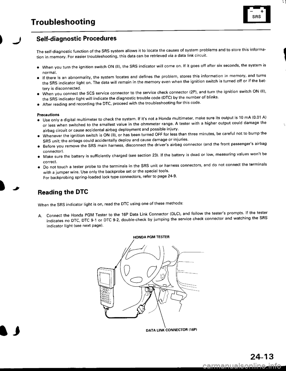
Reading the DTC
when the SRS indicator light is on, read the DTC using one of these methods:
A. Connect the Honda PGM Tester to the 16P Data Link Connector {DLC), and follow the tester's prompts lf the tester
indicatesnoDTc,DTcg-1orDTc9-2,doub|e-checkbyjumpingtheservicecheckconnectorandwatchingthesRS
indicator light (see next Page)
HONDA PGM TESTER
DATA LINK CONNECTOR Il6PI
l,
24-13
Page 1839 of 2189
Fuse
NumberFuse NameAmpsPage
BATTERY
Component or Circult Protected
Power distribution
lgnition switch
INTERIOR LIGHT | 7.5 | 10-10 | DLC, Ceiling light, Trunk light
FI E/M15 i(20 GX) i
i PGM-FI main relay, Fuel injection relay (GX)
Not used
POWER WINDOW| 10-10 | Power window relay
BACK UPStereo radio iuner ('9G'98 mod€ls), Audio unit ('99100
models), Heater control panel, PCM/ECM, TCM (9e'98
cvr)
HEADLIGHT
REAR DEFROSTER I
DOOR LOCK UNIT,
ROOF
i 10-12i Headlights
Not used
Rear window defogger relay
Power door lock control unit (all except '99-'00 models
with keyless), Keyless door lock control unit ('99-'00
models with keyless), Moonroof
i HORN, SrOP Lri 10-13i Horn relay, Brake switch
HAZARDHazard warning switch
OPTIONI 10-13I Security system (option)
i HEATER MOTOR Ii 10-1 i Blower motor relay
(CONDENSER FAN)
COOLING FANl1o-1
Condenser Jan relay, A'lC compressor clutch relay
Radiator tan relay
&5
Page 1852 of 2189
Power Distribution
- From Fuses to Relays and Components (cont'd)
-",JX-
I
I
\FUSE '3n{fEtbRUC|{T7.'.4
FUSE 44FI EA'!aacoa Dr6lc)
FUSE il8POUGNtvtl|Do{taoa
c351
c420PHOTO 63
I-.:CrJ
WIIT/ELX
1
I
I
I
I
FUELINJECTIONRELAYPage 25-1PHOTO 135
DATA LINKCONNECTOR(DLc)
Page 23-4,24-4, ot 25-4PHOfO 5001685 engine -
c419PHOTO 63
UNDER.DASHFUSE/RELAYBOXPHO|Q 5A
POWEBw]tDowNELAYPagE 120H$fa8
L-- ----- --20
wlIT/RED
-t
c420 6PHO|O 63vtEw 53
WHT/FEO
c407PHOTO 52Y|EW 2 ( 9& 00 modsrs)
c5s'rPHO|O 63
L-----JU DEN.DASHFUSE/RELAY BOXPHOfO 58
To Fuses 7, 8, 1 0, and I 1 ;tor deiails, s8€ PowerVYindotts, pa$ 120.
HatchbackCoup€ & S€dan
WHT/FED
(Sedan 1)
(e6-
101
,,, tr:::--*''.:lltut
(Not used)
i--l
tlL--J
TRUNKLIGHTPage 114-3
tl
tl
SPOT.LIGHTSPage 114-3
tl
tl
CEILINGLIGHTPage 114-3
* = Male-Femaleterminalsreversed for'99-'00 models
7A
tl
tl
PGM-FI MAINRELAYPage 23.24, ot 25
vtLw 18
I
I
PGM-FIRELAYPage 2324, ot 22
vtLw 18
i-,-x;-l
icontac{i
tlINTEGNATED
l__i!ffi*
10-10
Page 1863 of 2189
Ground Distributioh (conrd)
)
- G401
NOTE:
To G402on page14-5.
WINOSHIELOWIPERMOTORPage 91-1
DAYTIMERUNNINGLIGHTS
99.!rRoL cLUrcHuNr I swtTcH:?99^ Pases 23-5and 34-3vtEw 66 PHA|A 55
I
I
INJECTORCONTROLMODULEPage 25-1
I
I
3
. Wires shown without color codes are black.
o On Coupe and Sedan models, G401 is represented by ring terminals.
tl
tl
INTER.LOCK6611p99 PARKUN|T PINpaoe j38 SWITCHor ige_t Page 138PHoro6s of 138-1vtEw 26 PHOfO /7r-1 r-'t
tttl
CLUTCHINTER-LOCKSWITCHPage 21-2
ll
ll
ttl
rll
I
Itttl
'Ll;
I
n
t
M/T with 01685Cruise/D16Y5enginewith M/T
BRAKEFLUIDLEVELswtTcHPage 71ot 71-1
tl
tl
DOOR LOCK .CONTROLSTEERINGLOCKPage /3
tl
tl
UNITPage 130-12 ;
ttl
tt:
models
RNte 40
I
I
(
I
I czor
l'i1l?,
'97 mo
HORNPage 4
I
I
NFnl
s 9c.Plv'
BLK/RED
t
IJ;--
',f-l
DATA LINKCONNECTOR(DLC)Pages 23-4,24-4,25 4,44-1, and 47
30
14-6
G401