Page 152 of 2189

Valve Guides
7.
VALVESEAT
PFUSSIAN BTUE COMPOUNO
The actual valve seating surface. as shown by the
blue comDound, should be centered on the seat.
. lf it is too high (closer to the valve stem), you
must make a second cut with the 60'cutter to
move it down, then one more cut with the 45'
cutter to restore seat width,
. lf it is too low (closer to the vslve edge), you
must make a second cut with the 30" cutter to
move it uD, then one more cut with the 45'cutter
to restore seat width.
NOTE: The final cut should always be made with
the 45" cutter.
lnsert the intake and exhaust valves in the head and
measure the valve stem installed height.
Intake. Exhau3t Siem Installsd Height:
Standard (New): 53.17 - 53.6,4 mm
12.093 - 2.112 in)
Sorvice Limit: 53.89 mm (2.122 in)
lf the valve stem installed height is over the service
limit. reDlace the valve and recheck. lf its still over
the service limit, replace the cylinder head; the
valve seat in the head is too deep.
VALVE STEMINSTALLED HEIGHT
8.
\-
Replacement
1.As illustrated below, use a commercially-available
air-impact valve guide driver attachment modified
to fit the diameter of the valve guides. In most cases.
the same procedure can be done using the special
tool and a conventional hammer.
VALVE GUIDE DRIVERlCommerciallv available)5.3 mm
87 mm +- 57 mft
t3.43 in) | 12 24 inl
tr-r'10.8 mm(0.42 inl
or
VALVE GUIDE DRIVER, 5.5 mm
07742 - 0010100
Select the proper replacement guides. and chill them
in the freezer section of a refrigerator for about an
nour.
Use a hot plate or oven to evenly heat the cylinder
head to 300"F (150'C). Monitor the temperature with
a cooking thermometer.
CAUTION:
. Do not use a torch; it may warp the head.
Do not got the head hottel than 300"F (150"C1;
excessive heat may loosen thg valve seats.
To avoid burns. use heayy gloves whon handling
the heated cylinder h€ad.
{cont'd)
6-41
Page 153 of 2189

Valve Guides
Replacement (cont'd)
Working from the camshaft side, use the driver andan air hammer to drive the guide about 2 mm (0.1 in)towards the combustion chamber. This will knock offsome of the carbon and make removal easier.
CAUTION:
. Always wear satety goggles or a face shield when
driving valve guides.
. Hold the air hammer directly in line with thevalve guide to prevent damaging the driver.
Turn the head over, and drive the guide out towardthe camshaft side of the head.
VALVE GUIOE ORIVER,5.5 mm07742 - 001 01 00
It a valve guide still won't move, drill it out with a8 mm {5/16 in) bit, then try again.
CAUTION: Drill guides only in extreme cases; you
could damage the cylinder head it the guide breaks.
6. Remove the new guides from the freezer, one at atime, as you need them.
6-42
I7. Apply a thin coat of clean engine oil to the outsideof the new valve guide. Install the guide from thecamshaft side of the head; use the special tool todrive the guide in to the specified insralled height. lfyou have all 16 guides to do, you may have to reheat
the head.
VALVE GUIOEDRIVER,5.5 mm07742 - 0010100
ll
Valve Guide lnstalled Height:
Intake: 17.85 - 18.35 mm (0.703 - 0.722 inl
Exhausi: 18.65 - 19.15 mm (0.734 - 0.754 in)
VALVE GUIDE
Page 160 of 2189
Special Tools
(\
Ref. No. I Tool NumberDescriptionOty Page Relerence
q oTHAH PJ7010B
g I 07JAA-001020A
g I 07JAB-0010204
I 07JAB - 0010404
g 07LAJ - PR3020A
|6) 07MAA - PR70100
g I ozvu,r - enu orzo
g 07MAF - PR9010A
g 07742 - 0010100(!D I 07757-PJ10104
Valve Guide Reamer,5.5 mm
Socket, 19 mm
Holder Handle
Pulley Holder Attachment. 50 mm
Air Stopper
Tappet Adjuster
Tappet Locknut Wrench
Valve Spring Compressor Attachment ExtensionValve Guide Driver, 5.5 mm
Valve Spring Compressor Attachment
1 I 6-81
1 659
1 6-59
1 ] 6-5s
1 I 6-55
1 6-57
1 6-57
1 J 6-77
1 6-80, 81
1 6-71
ta;
aL)'n
-=<-,,LE;;
(D
a
6-50
\-
Page 162 of 2189

VTEC Control System
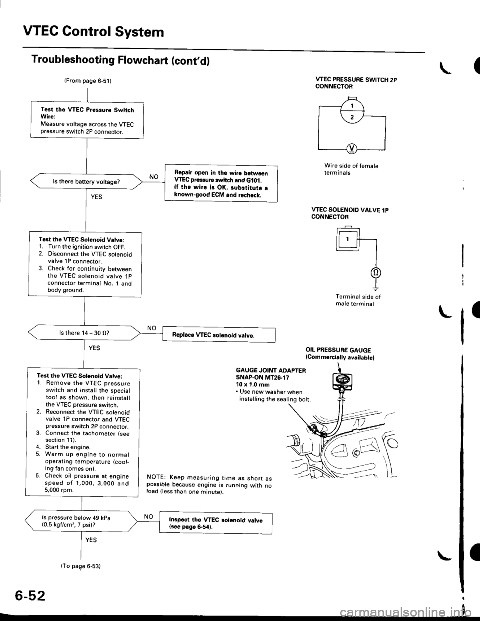
Troubleshooting Flowchart (cont,d)
VTEC PRESSURE SWITCH 2PCONNECTOR
Wire side of temaleterminals
OIL PRESSURE GAUGE(Comm.rcially avail.bte)
GAUGE JOINT ADAPTERSNAP.ON MT26.1710 x 1.0 ftm. Use new washer wheninstalling the sealing bott.
NOTE: Keep measuring time as shorr aspossible because engine is running witn noload lless than one minute).
6-52
(
VTEC SOLENOID VALVE lPCONNECTOF
Ir------r I
lLl.ll-r
II
It
Terminal side ofmale terminal
I
(From page 6-5l l
(To page 6-53)
Test tha VTEC P.es3uro SwitchWi.e:Measure voltage across the VTECpressure switch 2P connector.
Ropair opon in the wiro batwoenVIEC pr...urc switch and G lot .lf the wiro is OK, 3ubltitutr aknown-good ECM and rochack.
ls there battery voltage?
Test the VTEC Solenoid V.tve:1. Turn the ignition switch OFF.2. Disconnect the VTEC solenoidvalve 1P connector.3. Check for continuity betweenthe VTEC solenoid valve 1Pconnector terminal No, I andbody ground.
ls there 14 - 30 O?
Te3t the VTEC Sotonoid Vatve:'1. Remove the VTEC pressureswitch and install the specialtool as shown. then reinstallthe VTEC pressure switch.2. Reconnect the VTEC solenoidvalve 1P connector and VTECpressure switch 2P connector,3. Connect the tachometer (seesection 1l).4. Start the engine.5. Warm up engine to normaloperatrng temperature (cool-ing fan comes on).6. Check oil pressure at enginespeed of 1,000,3,000 and5,000 rpm.
ls pressure below 49 kPa(0.5 kgflcm,,7 psi)?Inipoct thg VTEC aolenoid valvel3ee P8go 6-54).
I
Page 163 of 2189

(From page 6-52)
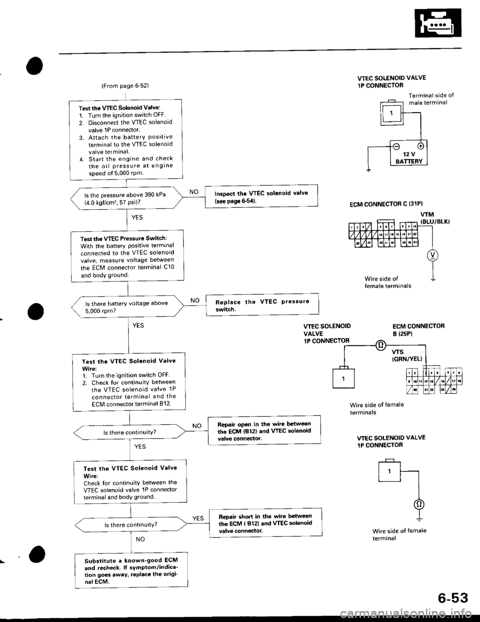
Test the VTEC Solenoid Valve:
1. Turn the ignition switch OFF
2. Disconnect the VTEC solenoid
valve 1P connector,
3. Attach the batterY Posrtrveterminal to the VTEC solenoid
valve terminal.4. Start the engine and check
the oil Pressure at engine
speed ol5,000 rPm
lrcoect the VTEC solenoid valve(see page S54)ls the pressure above 390 kPa(4.0 kgt/cm?, 57 Psi)?
Test the VTEC Pressure Switch:
With the battery Positive terminal
connected to the VTEC solenoid
valve, measure voltage between
the ECM connector terminal C10
and body ground.
ls there battery voltage above
5,000 rpm?
Test the VTEC Solenoid Valve
Wire:1. Turn the ignition switch OFF
2. Check for continuitv between
the VTEC solenoid valve 1P
con nector terminal and the
ECM connector terminal 812
Repair open in the wire between
the ECM lB12| and VTEC aolenoid
Test lhe VTEC Solenoid Valve
Wire:Check for continuity between the
VTEC solenoid valve'lP connector
terminal and body ground.
Repair short in the wiro b€'tween
the ECM ( 812) and VTEC aolenoid
Substitute a known'good ECM
and recheck. lI sYmptom/indica'tion goes away. repleca the origi-
nal ECM.
VTEC SOLENOID VALVE
1P CONNECTOR
Terminal side ofmale terminal
VIEC SOLENOIDVALVE1P CONNECIOR
ECM CONNECTORB l2sP)
ECM CONNECTOR C (31PI
WM
Wire side ot female
termrnals
VTEC SOLENOID VALVE
1P CONNECTOR
I'ft
I
I
Wire side of female
termanal
6-53
Page 165 of 2189

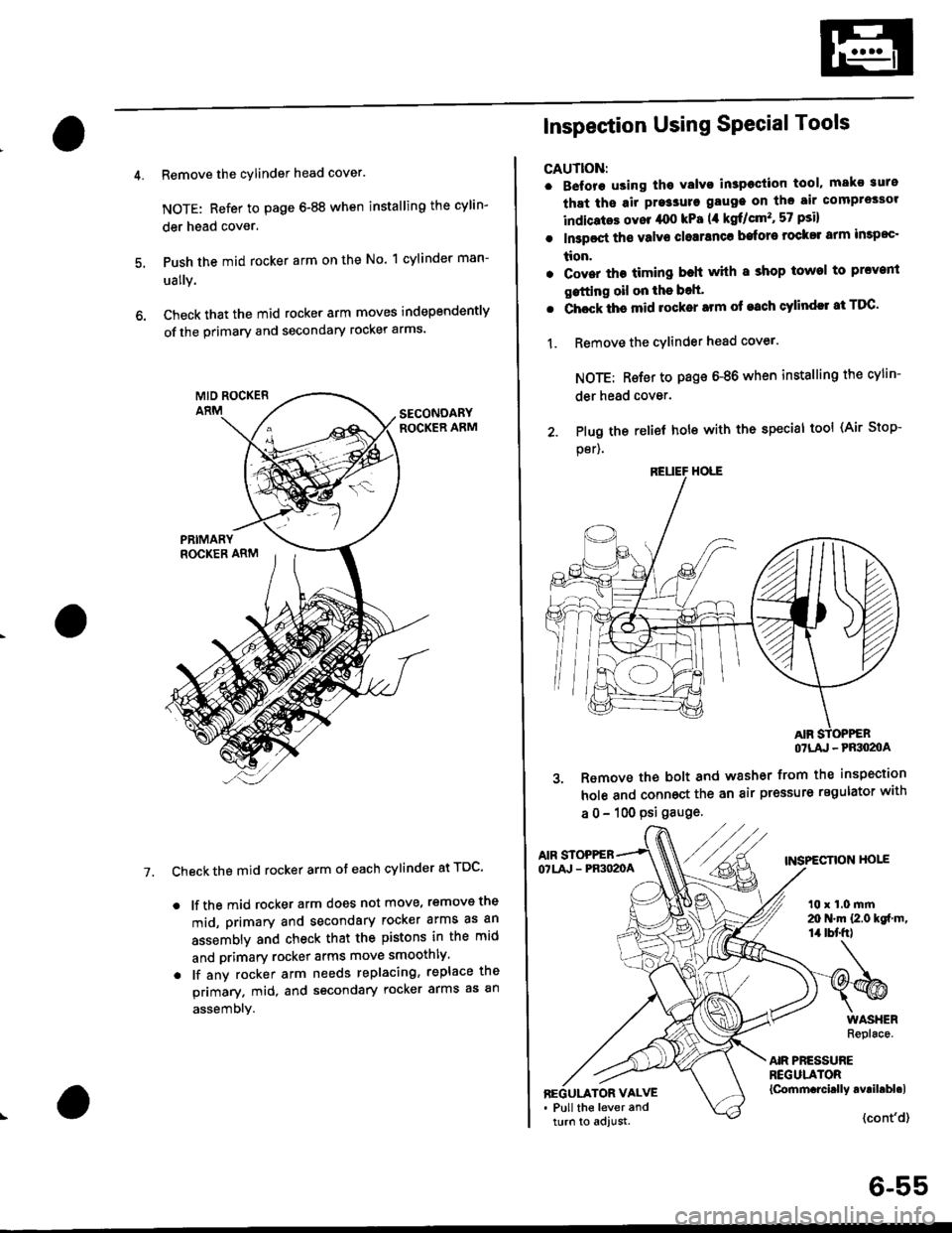
Remove the cylinder head cover.
NOTE: Refer to page 6-88 when installing the cylin-
der head cover.
Push the mid rocker arm on the No. 1 cylinder man-
ually.
Check that the mid rocker arm moves independently
of the primary and secondary rocker arms.
Check the mid rocker arm ot each cylinder at TDC'
. lf the mid rocker arm does not move, removs the
mid, primary and secondary rocker arms as an
assembly and check that the pistons in the mid
and primary rocker arms move smoothly.
. lf any rocker arm needs replacing, replace the
primary. mid, and secondary rocker arms as an
assembly.
7.
2. Plug the
per).
Inspection Using SPecial Tools
CAUTION:
. B€fore using tho Yalvo inspeciion tool, mako suro
that ths air pre3sure gauge on the air comprossor
indicatos ovor /rco kPa (,1 kgf/cm'�, 57 psi)
. In3poct ths valve closranca bafore rock$ arm impoc'
tion.
. Cover the timing beh whh I shop towel to prcvenl
gstting oil on the bolt'
. Chock ths mid rocker arm of each cylindll at TDC'
1. Remove the cYlinder head cover.
NOTE: Rsfer to page 6-86 when installing the cylin-
der head cover.
relief hole with the special tool (Air Stop-
OTLA' - PRSO2OA
3. Remove the bolt and washer from the inspection
hole and connoct the an air pressure regulator with
a 0 - 100 psi gauge.
AIF STOPPEBTNSPECTION HOIEOTLA' - PR3O2OA
t0 x 1.0 mrn20 N.m {2.0 kgf m,14 tbt'fr)
AIR PRESSUREREGULATOR{Cornm.rcirlly avril.bl.lBEGULATOR VALVE. Pull the lever andturn to adjust.{cont'd}
6-55
Page 166 of 2189
VTEC Rocker Arms
4.
Inspection Using Special Tools (cont,dl
Loosen the valve on the regulator and apply thespecified air pressure.
Specified Air Pressuro:
250 kPa {2.5 kgtlcm,, 36 psil- 490 kPa {5.0 kgtcm,, 7t psil
Make sure that the primary and secondary rockerarms are mechanically connected by the pistonsand that the mid rocker arms do no. move wnenpushed manually.
SECONDARYROCKER ARM
. lf any mid rocker arm moves independently ofthe primary and secondary rocker arms, replacethe rocker arms as a set.
Remove the tools.
Check the operation of the lost motion assembly bypushing on the mid rocker arm. The lost motionassembly should compress fully and operatesmoothly through its full stroke. Replace the assem_bly if it does not work smoothly.
After inspection. check that the Malfunction Indi_cator Lamp {MlL) does not come on.
7.
6-56
I
ll
;l
Page 179 of 2189
WATER BYPASS
HOSE
14. Remove the upper radiator hose, heater hose and
water bvpass hose.
HEATER
Remove the engine wire harness connectors and wlre
harness clamps from the cylinder head and the intake
manifold.
Four fuel injector connector
Engine coolant temperature (ECT) sensor connec-
tor
ECT gauge sending unit connector
ECT switch connector
ldle air control (lAC) valve connector
Manifold absolute pressure (MAP) sensor connec-
tor
Throttle position sensor connector
Primary Heated oxygen sensor (Primary HO2S)
connecror
VTEC solenoid valve connector
15.
a
a
a
a
a
\
16.
17.
Remove the spark plug caps and distributor form
the cylinder head.
Remove the upper bracket.
NOTE:
. Use a jack to support the engine before removing
the upp€r bracket is removed.
. Place a cushion between the oil panandthejack.
12 x 1.25 fin74 N.m 17.5 kgtm,
UPPER BRACKET
18. Remove the cylinder head cover.
{cont'd)
6-69