1996 HONDA CIVIC Mount replacement
[x] Cancel search: Mount replacementPage 784 of 2189
Shift Control Solenoid Valve A/B Assembly
Test
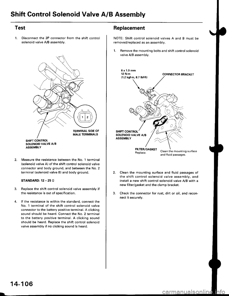
1. Disconnect the 2P connector from the shift control
solenoid valve A,/B assemblv.
SHIFT CONTROLSOLENOID VALVE A/B
ASSEMBLY
N4easure the resistance between the No. 1 terminal(solenoid valve A) of the shift control solenoid valve
connector and body ground, and between the No. 2
terminal (solenoid valve B) and body ground.
STANDARD: 12 - 25 O
Replace the shift control solenoid valve assembly if
the resistance is out of specification,
lf the resistance is within the standard, connect the
No. 1 te.minal of the shift control solenoid valve
connector to the battery positive terminal. A clicking
sound should be heard. Connect the No. 2 terminal
to the battery positive terminal. A clicking sound
should be heard. Replace the shift control solenoid
valve assembly if no clicking sound is heard.
14-106
Replacement
NOTE: Shift control solenoid valves A and B must be
removed/replaced as an assembly.
1. Remove the mounting bolts and shift control solenoid
valve A,/B assembly.
5xL0mm12 N.m(1.2 kgf.m,8.7 lbf.ft)CONNECTOR BRACKET
FILTER/GASKETBeplace.Clean the mounting surfaceand fluid passages.
Clean the mounting surface and fluid passages of
the shift control solenoid valve assembly, and
install a new shift control solenoid valve Ay'B with a
new filter/gasket and the clamp bracket.
Check the connector for rust. dirt or oil. and recon-
nect it securelv,
Page 786 of 2189

Mai nshaft/Cou ntershaft
Linear Solenoid AssemblySpeed Sensors
Replacement
1. Remove the mounting bolts and the linear solenoid
assemory.
Clean the mounting surfaceand flu id passages.
6x1.0mm12 N.m 11.2 kgl m,8.7 tbf.ftl
@
@
GASKET
Clean the mounting surface and fluid passage of the
linear solenoid assembly and transmission housing.
Install a new linear solenoid assembly with a new
gasl(et.
NOTE; Do not pinch the gasket when installing the
linear solenoid; make sure that the gasket is installedproperly in the mounting groove of the linear sole-
noid.
Check the linear solenoid connector for rust, dirt or
oil, and connect it securely,
LINEARSOLENOIDASSEMELY
I
14-108
Replacement
't.
6x128.7
Remove the 6 mm bolt and the countershaft speed
sensor from the right side cover.
COUNTERSI{AFTSPEED SENSOR
O.RINGReplace.
MAINSHAFTSPEEDSENSOR
MAINSHAFT SPEEDSENSOB WAS}IER(D16Y7 enginel
6x1.0mm12 N.m (1.2 kgf m,8.7 tbf.ft)
1.0 mmN.m (1.2 kgf.m,rbf ft)
\\
/,
%/E:)
Remove the 6 mm bolt and the mainshaft sDeed
sensor from the transmission housino.
Replace the O-ring with a new one before installing
the countershaft speed sensor or th€ mainshaft speed
sensor.
NOTE: Installthe mainshaft speed sensor washer on
the mainshaft speed sensor. The mainshaft speed
sensor washer is used on models with the D'|6Y7
engine.
Page 979 of 2189

Lower Valve Body Assembly
Replacement
@ Make sure lifts, iacks, and saf€ty stands
are placsd prop€rly {sea section 1).
CAUTION: While removing and installing th6 lower
valve body asssmbly, b€ sule not to allow dust and
other for€ign particles to entsr inio the transmksion.
1. Raise the front of the vehicle, and support it with
safetv stands (see section 1).
2. Set the parking brake, and block both rear wheels
securetv.
4.
6.
Remove the drain plug, and drain the CVT fluid.
Reinstall the drain plug with a new sealing washer(see page 1+299).
CAUTION: Keop all of other toreign parliclos out of
the transmission.
Disconnect the 8P connector from the solenoid har-
ness connector.
Remove the ATF cooler hoses at the ATF cooler
lines. Turn the ends of the ATF cooler hoses up to
prevent ATF from flowing out, then plug the ATF
cooler noses.
CAUTION: Keep all of other foroign particlo3 out of
tho transmission.
Remove the right front mounvbracket.
10 x 1.25 mmila N.m (,1.5 kgf.m, 33 lbtft)
RIGHT FRONTMOUNT/BRACKET
ATF COOLER LINE
10 x 1.25 mmsil N.m 15.5 kgf.m,40 rbr.ft)
ATF COOLER HOSE
14-302
14.
7. Remove the ATF cooler outlet line.
8. Remove the ATF cooler line bracket bolt.
9. Remove the ATF pan (fourteen bolts).
10. Remove the ATF strainer (two bolts).
1 l. Remove the one bolt securing the solenoid harness
connector,
12. Remove the
bolts).
lower valve body assembly (eight
LINE BOLT28 N.m (2.9 kgtm,21 lbtft)SEALINGReplace.
ATF COOI.-EROUTLET
OOWEL PIN
O.RINGFeplace.
SOLENOIO HARNESSCONNECTOR
5x1.0mm12 N.m 11.2 kgt.m,8.7 tbt.ftlO.RINGReplace.ATFSTNAINER
6x1.0mm12 N.m 11.2 kgt m,E.7 tbt'ft)
OOWEL NN
BODY ASSEMBLY
6x1.0mm12 N.m 11.2 kgf.m,8.7 rbf.ft)
ATF PAN GASKETReplace.
VALVE
ATF COOLER INLETUNE BRACKET BOLT8 x 1,25 mm26 N.m {2.7 kgf.m,20 tbf.frl
13.
ATF PANx 1.0 mm12 N.m 11.2 kgf.m, E.7 lbf.ftl
Install the new lower valve bodv in the reverse
ordgr of the removal orocedure.
CAUTION: Koep all ot other fo.oign particles out of
ths transmission.
NOTE:
. Replace the following parts:
- O-rings on the solenoid harness connector
and the ATF strainer- ATF pan gasket- Sealing washers
. lf the ATF cooler inlet line bracket is bent or
warped, put it back to the original position.
Perform the start clutch calibration orocedure on
page 14-293.
Page 1060 of 2189
Inspection and Adjustment
Steering Operation
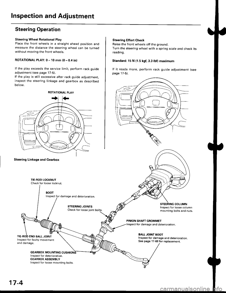
Steering Wheel Rotational Play
Place the front wheels in a straight ahead position andmeasure the distance the steering wheel can be turnedwithout moving the front wheels.
ROTATIONAL PLAY: 0 - 10 mm (0 - 0.4 in)
lf the play exceeds the service limit, perform rack guide
adjustment (see page lT-5).
lf the play is still excessive after rack guide adjustment,inspect the steering linkage and gearbox as descrjbed
Detow.
Steering Linkage and Gearbox
TIE.ROO LOCKNUTCheck for loose locknut.
BOOTInspect for damage and deterioration.
STEERING JOINTSCheck for loose joint
END BALL JOINTInspect for faulty movementano oamage.
GEABBOX MOUNTINGInspect f or deterioration.GEABBOX ASSEMBLY
Ste€ring Effort Check
Raise the front wheels off the ground.
Turn the steering wheel with a spring scale and check itsreaorng,
Standard: 15 N (1.5 kgf, 3.3 lbll maximum
lf it reads more. perform rack guide adjustment (see
page 17-5).
COLUMNInspect for loose columnmounting bolts and nuts.
PINION SHAFT GROMMETfor damage and deterioration.
BALL JOINT BOOTInspect for damage and deterioration.See pago 17-68 tor replacement.
ao-\---------U
17-4
Inspect for loose mounting bolts.
Page 1087 of 2189
ISteering Linkage and Gearbox
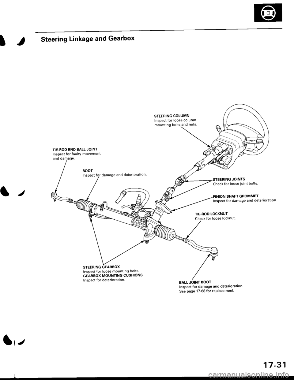
TIE-ROD END BALL JOINT
Inspect for faulty movement
and damage.
STEERING COLUMN
Inspect for loose column
mounting bolts and nuts
BOOTInspectdamage and deteriorataon
STEERING GEARBOXlnspect for loose mounting bolts.
GEARBOX MOUNTING CUSHIONS
Inspect f or deterioration
STEERING JOINTSCheck for loose joint bolts.
l./
TIE-ROD LOCKNUTfor loose locknut
BALL JOINT BOOT
Inspect for damage and deteriorataon'
See page 17-68lor replacement.
SHAFT GROMMETInspect for damage and deteriorataon.
lrz
17-31
Page 1132 of 2189
Front Suspension
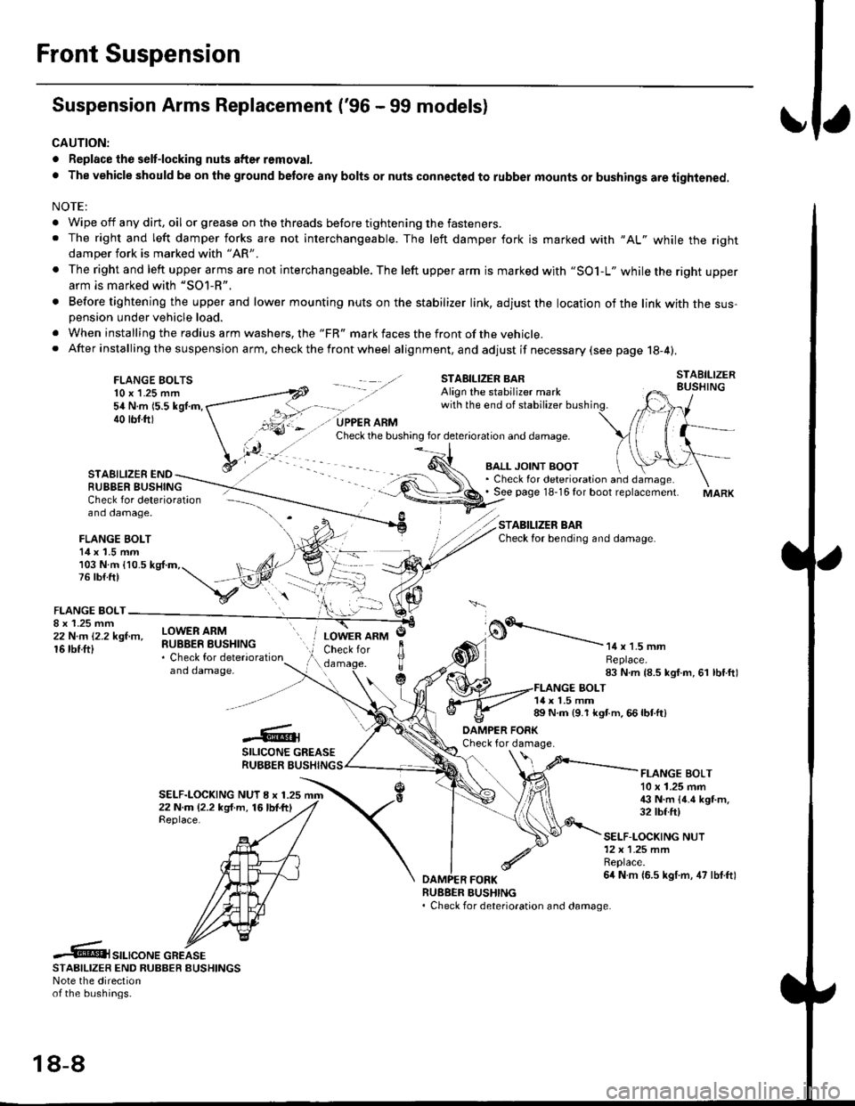
Suspension Arms Replacement ('96 - 99 models)
CAUTION:
. Replace the selt-locking nuts after removal.
. The vehicle should be on the ground betore any bolts or nuts connected to rubber mounts or bushings are tightened.
NOTE:
. Wipe off any dirt, oil or grease on the threads before tightening the fasteners.. The right and left damper forks are not interchangeable. The left damper fork is marked with "AL" while the rightdamper fork is marked with "AR'
. The right and left upper arms are not interchangeable. The left upper arm is marked with "SO1-L" while the right upperarm is marked with "SOl-R".
. Before tightening the upper and lower mounting nuts on the stabilizer link, adjust the location of the link with the sus-pension under vehicle load.
. When installing the radius arm washers, the "FR" mark faces the front ofthe vehicle.. After installing the suspension arm, ch eck the front wheel alignment, and adjust if necessary (see page 18-4).
FLANGE BOLTS10 x 1.25 mm54 N.m 15.5 kgl.m,40 tbf.ftl
STAEILIZER ENDRUBBER BUSHING
BALL JOINT BOOT. Check for deterioration and damage.. See page 18-16 for boot replacement.
STABILIZER BARCheck for bending and damage.
Check for deterioration - ---\--
and damage, -\
FLANGE BOLT14 x 1.5 mm/)l103 N.m {10.5 kg{.m,. t, ,/4,76lb{.ft) t,,"-iV
v:\FLANGE BOLT-
;iffillr-"- ilHitffi*::,"*"
and damaoe,
o.'-----------14 x 1.5 mmReplace.83 N.m {8.5 kgf.m, 61 lbf.ftl
LOWER ARMCheck for
c
JlTTda
1{ x 1.5 mm89 N.m {9.1 kgt m. 66 lbtft)
-6;SILICONE GREASERUBBER BUSHING
DAMPER FORKCheck for damage.
SELF-LOCKING NUT I x 1.2522 N.m (2.2 kg{.m, 16lbf.ftlReplace.
FLANGE BOLT10 x 1.25 mm€ N.m {4.6 kgt m.32 tbf.ft)
SELF-LOCKING NUT12x 1.25 mmReplace.6it N m {6.5 kgf.m, 47 lbf.ftl
RUEBER BUSHING. Check for deterioration and damage.
.6t",.,"o".c"KeSTAAIL|zER END RUBBER EUSHINGSNote the directionof the bushings.
18-8
Page 1133 of 2189
I
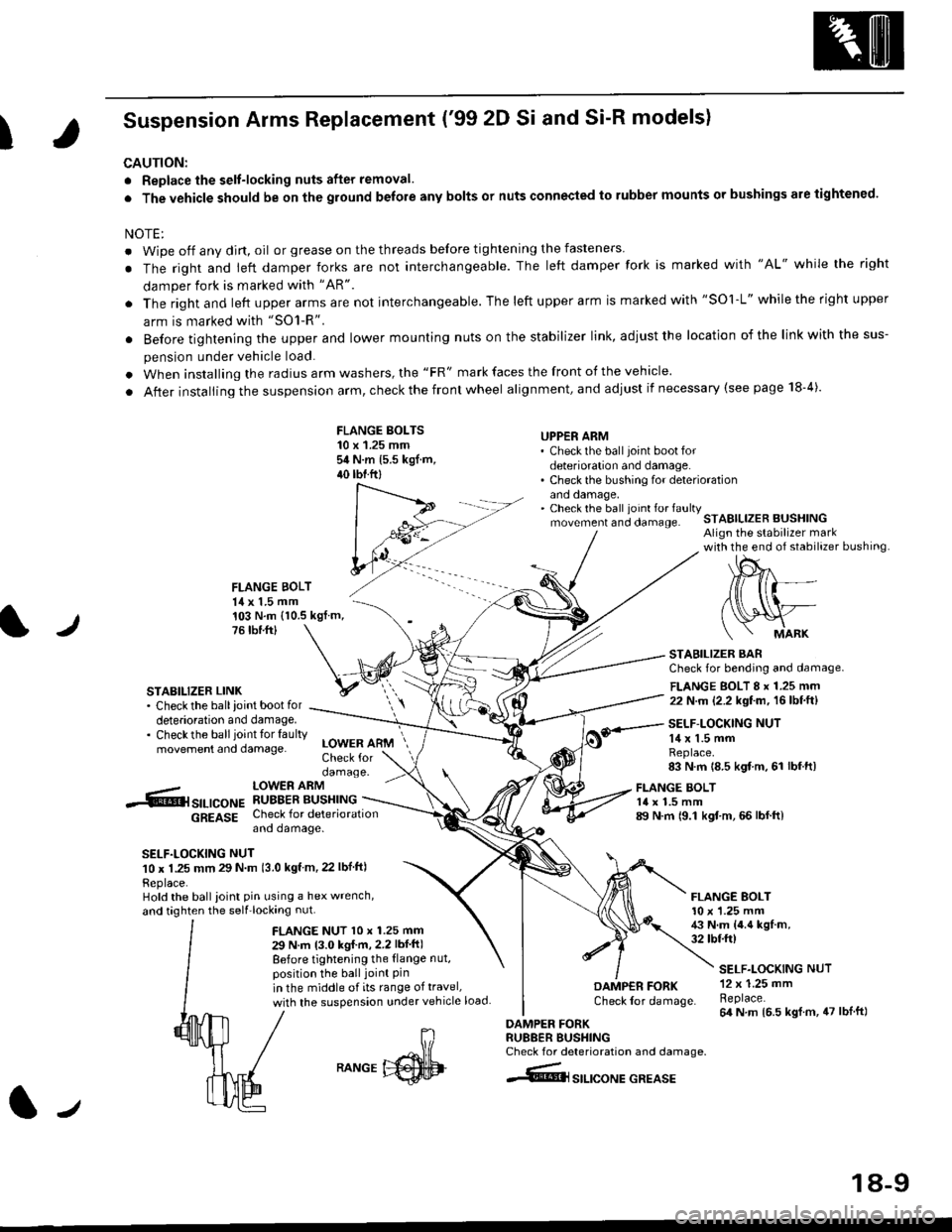
Suspension Arms Replacement ('99 2D Si and Si-R models)
CAUTION:
. Replace the selt-locking nuts after removal.
. The vehicle should be on the ground belore any bolts or nuts connected to rubber mounts or bushings are tightened.
NOTE:
. Wipe off any dirt, oil or grease on the threads before tightening the fasteners
. The right and ieft damper forks are not interchangeable. The left damper fork is marked with "AL" while the right
damper fork is marked with "AR"
. The right and left upper arms are not interchangeable. The left upper arm is marked with "SOl-L" while the right upper
arm is marked with "SO1-R".
. Before tightening the upper and lower mounting nuts on the stabilizer link, adiust the location of the link with the sus-
pension under vehicle load.
. When installing the radius arm washers, the "FR" mark faces the front of the vehicle.
. After installing the suspension arm, check the front wheel alignment, and adjust if necessary (see page 18-4).
FLANGE BOLTS10 x 1.25 mmsit N.m 15.5 kgf.m,40 tbtftl
UPPER ARM' Check the ball joint boot fordeterioration and damage.. Check the bushing for deteriorationano oamage,. Check the ball ioint fo. faultymovement and clamage.STABILIZER BUSHINGAlign the stabilizer markwith the end of stabilizer bushing
FLANGE BOLT14 x 1.5 mm
l./
103 N.m (10.5 kgf.m,76 tbr.ftl
STABILIZER LINK. Check the ballioint bootfordeterioration and damage.. Checkthe ballioint tor faultymovement and damage.
STABILIZER BARCheck for bending and damage.
FLANGE BOLT 8 x 1.25 mm22 N.m (2.2 kgf.m, 16lbf.ft)
SELF-LOCKING NUT14 x 1.5 mmReplace.83 N.m 18.5 kgf m, 61 lbf.ft)
-.6r srr-,co", hSHrtlrT.[*"u
6g619g Check for deteriorationano oamage.
SELF.LOCKING NUT10 x 1.25 mm 29 N m 13.0 kgf m, 22 lbf ftl
Replace.Hold the ball ioint pin using a hex wrench,
and taghten the self'locking nut.
LOWER ARMCheck fordamage.
FLANGE NUT l0 x 1.25 mm
29 N.m 13.0 kgI m,2.2 lbf ft)
Before tightening the {lange nut,position the ball joint Pinin the middle of its range of travel,
with the suspension under vehicle load
FLANGE BOLT14 x 1.5 mm89 N.m 19.1 kgf.m, 66 lbf.ft)
FLANGE BOLT10 x '1.25 mm43 N.m {4.4 kgf.m,32 tbtft)
DAMP€R FORKCheck lor damage.
DAMPER FORKRU88ER BUSHINGCheck for deterioration and damage.
4@lsrlrcoNE GREASE
SELF.LOCKING NUT12 x 1.25 mmReplace.64 N m 16.5 kgl.m, 47 lblft)
J
RANGE
18-9
Page 1134 of 2189
Front Suspension
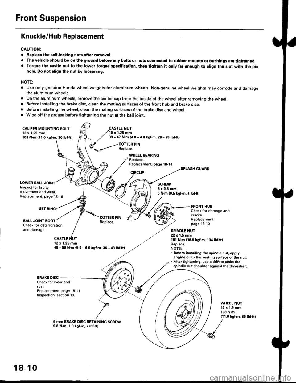
Knuckle/Hub Replacement
CAUTION:
. Replaco tho salf-locking nuts after romoval.
. The vehiclo should be on tho ground bsfore any bohs or nuls connected to rubber mounb or bushings are tightened.. Torqu€ th€ castle nut to the lowor torque specification, ihen tighton it only far enough to align th€ slot whh the pin
hole. Do not align the nut by loosening.
NOTE:
. Use only genuine Honda wheel weights for aluminum wheels. Non-genuine wheel weights may corrode and damagethe aluminum wheels.
. On the aluminum wheels, remove the center cap from the inside of the wheel after removing the wheel,. Before installing the brake disc, clean the mating surfaces of the front hub and brake disc,. Before installing the wheel, clean the mating surfaces of the brake disc and wheel.o Wipe off the grease before tightening the nut at the ball joint.
CALIPER MOUNTING BOLT12 x 1.25 mm108 N.m {11.0 kgl.m, 80lbf.ft)
LOWER BALL JOINTInspect for faultymovement and wear.
CASTLE NUT10 r 1.25 mm39 - ia7 N.m (4.0 - 4.8 kgf.m, 29 - 35 lbf,ftl
COTTER PINReplace.
WHEEL BEARINGReplace.Replacement, page 18-14
CIRCLIP
SCREW5x0.8mm5 N.m {0.5 ksl.m, 4 lbf.ftlReplacement, page 18-16
SET RING
BALL JOINT BOOT
FRONT HUBCheck for damage andcracks.Replacement,page 18-10Check for deteriorationand damage.
CASTLE NUT12 x 1.25 mm49 - 59 N.m l5.O - 6.0 kg{.m. 36 - /(} lbf,ftl
SPINDI.T ]{UT22 r 1.5 mmlEl N.m {18.5 kgf.rn, 13{ lbl.ttlReplace.NOTE:. Before instelling the spindle nut. apply6n9ine oilto th6 seating surface ofthe nut.. Atter tightening, uso a drift to stake thespindle nut should6r against the driveshaft.
BRAKE DISCCheck for wear andrust.Replacement, page 18-11lnspection, section 19.
WHEEL NUT12 x 1.5 mm'108 N.m1r1.0 kgf.m, 8lt lbf.ft)
6 mm BRAKE DISC RETAINING SCREW9.8 N.m 11.0 kgf.m, 7 lbtft)
18-10