1996 HONDA CIVIC Hose connection
[x] Cancel search: Hose connectionPage 557 of 2189
Emission Control System
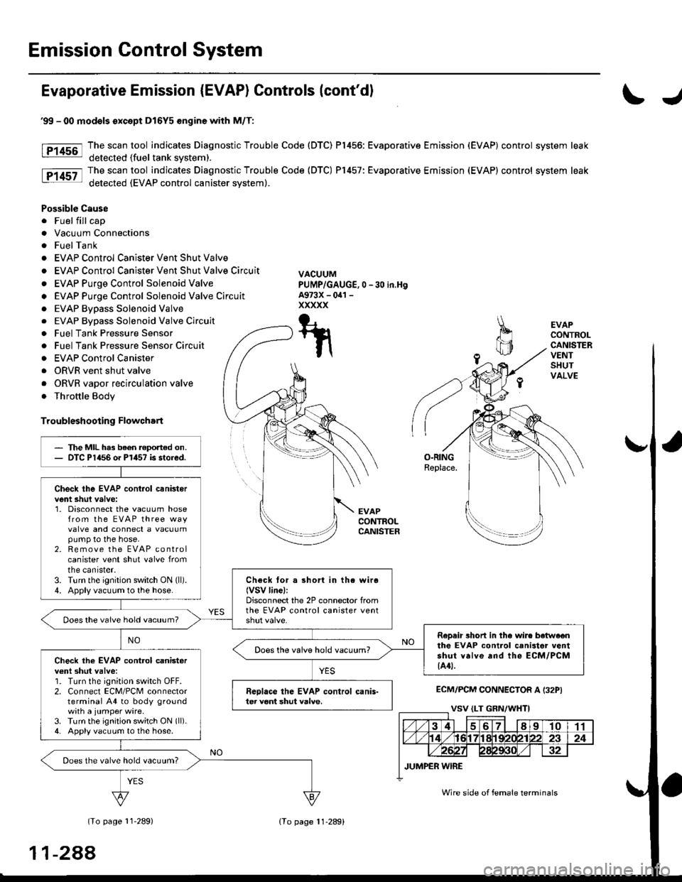
Evaporative Emission {EVAP) Controls (cont'dl
\J
tF1456-l
tP14sz-l
EVAPCONTROLCANISTERVENTSHUTVALVE
O.RINGReplace.
EVAPCONTROLCANISTER
ECM/PCM CONNECTOR A I32PI
(To page 11'289)
'99 - 00 modols except Dl6Y5 engine with M/T:
The scan tool indicates Diagnostic Trouble Code (DTC) P1456: Evaporative Emission (EVAP) control system leak
detected (fuel tank svstem).
The scan tool indicates Diagnostic Trouble Code (DTC) P1457: Evaporative Emission (EVAP) control system leak
detected (EVAP control canister system).
Possible Cause
. Fuel fill cap
. Vacuum Connections
. FuelTank
. EVAP Control Canister Vent Shut Valve
. EVAP Control Canister Vent Shut Valve Circuit
. EVAP Purge Control Solenoid Valve
o EVAP Purge Control Solenoid Valve Circuit
. EVAP Bypass Solenoid Valve
0 -30 in,Hg
. EVAP Bypass Solenoid Valve Circuit
. Fuel Tank Pressure Sensor
. Fuel Tank Pressure Sensor Circuir
. EVAP Control Canister
. ORVR vent shut valve
. ORVR vapor recirculation valve
. Throttle Body
Troubleshooting Flowchart
VACUUMPUMP/GAUGE,A973X - oal -
xxxxx
T-t
t\
The MIL has been reported on.DTC P1456 o. P1457 is stored.
Check the EVAP cont.ol canistervent shul valve:1. Disconnect the vacuum hosefrom the EVAP three wayvalve and connect a vacuumpump to the hose.2. Remove the EVAP controlcanister vent shut valve fromtne canrster.3. Turn the ignition switch ON (ll).
4. Apply vacuum to the hose.Check for a short in the wiro(VSV linel:Disconnect the 2P connector fromthe EVAP control canister ventDoes the vaive hold vacuum?
RoDair 3hort in the wire botwe€nthe EVAP control canilter ventshut valve and the ECM/PCM{A4t.
Does the valve hold vacuum?Check the EVAP cont.ol canisterv€nl shut valve:1. Turn the ignition switch OFF.2. Connect ECM/PCM connectorterminal A4 to body groundwith a jumper wire.3. Turn the ignition switch ON (ll).
4. Apply vacuum to the hose.
Reolace the EVAP control canis-ter veni shut valve.
Does the valve hold vacuum?
Wire side of female terminals
11-288
lTo page 11-289)
Page 679 of 2189

Automatic Transmission
Special Tools ......... .....'."".'-.-.' 14'2
Description .,....................-...... 14-3
power Flow ......,................. 14"6
Elestronic Control System .... . ................'..'.'.. 14-13
Hvdraulic Control .....'......" 1'l-19
Hydraulic F|ow...... .'.'.".'....11-21
Lock-up System '............ ... t/t'33
Electrical System
Component Locations....,.............'......'.............'.,. 14'39
PCM Circuit Diagram
lA/T Control Syst€m: '96 - 98 Models) .........'.. 1/t-40
PCM Tarminal Volt8ge/Measuring Condhions
{'96 - 98 ModeblA/T Control System ............
PCM Circuit Disgram(A/T Conlrol System: '99 - 00 Modsls) '..........' 14-44
PCM Terminal Voltage/Measuring Conditions('99 - 00 Models)A/T Control System ...
Troubleshooting Proceduros ....
Symptom-to-ComPonent Chari
Efectricaf SFiem - '96 - 98 Models '..-.-..."'.'..11-52
Eloqtrical System -'99 - 00 Modols ... .........". 1+54
EleclricatTroubl$hooting ('96 - 98 Models)
Valve Body
Repair .................... ........'.... 14-139
Valve
Assembly
ATF Pump
1,1-1i10
Inspection ...........'.......... 14-141
Main Valvs Body
Disass€mbf y/lnspoction/R.sssembly .'.'.'.'.. -. -. 1 1-1 12
Secondsry Valve BodY
Disa$embfy/lnspoction/Rsassembly ......'.'.'.'. 11-111
Regulator Valve Body
Disa$embly/lnspoction/Rea3sembly ..........'... 14-1{5
Servo Body
Disassombly/lnsp€ction/Reassembly .".'........ 14-146
Lock-up Valv6 Body
Dis$s.mbf y/ln3poction/Rea$embly .'.. -. -..'.'.' 1 1-1 17
Mainsh!ft
Dkassembly/lnep€ction Reassembly ..'...'........ 14'148
Inspoction .............'..........'. l it-149
Countsrshaft
Disa$embly/lnspeqtion/Rea3sembly .......'...'.. 1a-l51
Dba$ombly/Re$s.mblY11-152
til-46
I rl-48
Troubleshooting Flowcharts
Electrical Troubleshooting ('9!t - 00 Models)
Troublsshooting Flowchart3
Lock-up Control Solenoid vslvo A/B AssemblY
RePlacoment
Shift Cont.ol Solenoid Valve A/B A3sembly
Inspestion
Ona-way Clutch
Disassembh/lrupoction/Rca$embly .. "'........ l4-155
Clutch
lllustlttcd Ind.x {A48A, B4RA Transmlssion) ..' 14-156
tustr.tod Index (MrnA Transmi$ionl ............ til-158
...................... 14-153
L
14-56
1+81'
14-105
1+105
Replacoment ......
Mainshaft/Countorshaft Spo€d Sonsors
Replacemsnt ......'."'........... lit'108
Hydraulic System
Symptom-to-Componeni Chart
Hydraulic Sydemr+109
t4-113
1+116
11-117
Rea$emblY
14-106 Difforrr ial
llhdraied Index........ t4-156
B.ckhrh ln3poction. 14-167
Boaring Roplacemont..-..........11-167
..... 14-108 Diftrrsniial Carrior Repl8cemeni .'.-.............'...' lil-168
Oil Sall Romovalt4-t 59
Oil Soal ln3tallstion/Sidc Clearance'......'.....'... 1'l'169
Torqua Convertcr Housing Boarings
Mlin3haft Besring/Oil Scal Roplac.ment ."..'.. lil-172
Counio6hatt Betring R.plscem.nt ..'...... ....... 14-173
Test.....,......14-106
14-107
14-160
11-162
11-171
11-175
Replacement
Test .....,.,..........
Road Te3t
Linear Solenoid AsssmblY
Stall Speed
lllustrated Indax
Transmission/End Cover'. ....
Transmission Hou3ing,.............'.'......'....""..-.-.. 11-128
Torque Conve.ter Housing/Valvo Body ........... 14-130
End Cover
14-itB Park Stop
1+119 In3pection/Adiustmsnt...'......'.'............'...."""'14-175
Transmbgion
Reassombly
11-122 Torquo Convertet/Drivr Plsie ............'.'............'.. . l4-182
Transmission
11.726 Inrtallation
Tranlmission Housing Boarings
Msinsh.ft /CounteEhaft Bearings
B!pltcomgnt
Rcvo.3s ldlor Gear
lnrtallation
Cooler Flushing ..
Shift Cabls
Test
Fluid Level
Checkin9 .........."..'.'.....
Changing
Pressure Testing
Transmission
Transmission
Rgmoval ..
lil-176
.'..........'.'.'..... 1'l-183
.... lil-187
11-132Adiustmont
RemovaUlnttallation1,1-190
lit-191Transmisgion Housing
Removal ... '.'...... ......'..... 14-l3il
Tolque Convgrter Housing/valvs Body
Rsmoval .........,...... ............. 14-136
Valve CaDs
Description .......'................. t 4'138
Shift lndicator Panel
Adiu3tmant ..'.................. 14-192
ATF Coolor Hoses
Connection ..,............,.,....... l'l-192
Shift Lever .,........
Page 870 of 2189

Shift Indicator PanelATF Cooler Hoses
Adiustment
'1.Check that the index mark on the indicator alionswith the N mark on the shift indicator panel whenthe transmission is in NEUTRAL.
3 N.m {0.3 kgf.m, 2lbt.ftl
lf not aligned. remove the front console {see section20t.
Remove the shift indicator panel mounting screwsand adjust by moving the panel,
NOTE: Whenever the shift indicator panel is removed,reinstallthe panel as described above,
INDEX MARK
L
14-192
Connection
1. Connect the ATF cooler hoses to the ATF cooler linesand ATF cooler, and secure them with the clips asshown.
TRANSMISSION CLIP
Page 1095 of 2189
Power Steering Hoses, Lines
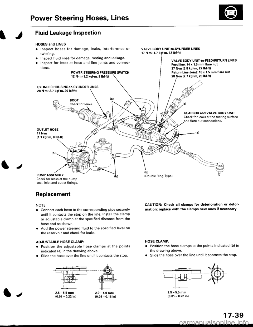
Fluid Leakage Inspection
HOSES and LINES
. Inspect hoses for damage, leaks, interference or
twisting.
. Inspect tluid lines for damage, rusting and leakage.
. Inspect for leaks at hose and line joints and connec-
tions.
POWER STEERINGswtTcH12 N.m {1.2 kgt.m,9lbt.ft}
CYLINDER HOUSING-to.CYLINDER LINES28 N.m (2.7 kgf.m, 20 lbf.ft)
VALVE BODY UNIT-to-CYLINDER LINES'17 N.m {1.712 tbl.ftl
VALVE BODY UNIT-Io-FEED/RETURN LINES
Feed line: 14 x '1.5 mm llare nut
37 N.m {3.8 kgJ.m, 27 lbf'tt)
Return Line Joint 16 x 1.5 mm flare nut
28 N m 12.7 kgf.m,20 lbtft)
HOSE CLAMP:
. Position the hose clamps at the points indicated (b) in
the drawing above.
. Slide the hose over the line until it contacts the stop.
8()07Check for leaks.
OUTLET HOSE11 N.m
G€AR8OX and VALVE BODY UNITCheck for leaks at the mating surfaceand flare nut connections,
tbt(Double Ring Typei
CAUTION: Check all clamps for deterioration or delor-
mation; replace with the clamps new ones il necessary.
(1.1 kgf.m,8
PUMP ASSEMBLYCheck for leaks at the pump
seal, inlet and outlet fiftings.
Replacement
NOTE:
. Connect each hose to the corresponding pipe securely
until it contacts the stop on the line. Install the clamp
or adiustable clamp at the specified distance from the
hose end as shown.
. Add the power steering fluid to the specified level on
the reservoir and check for leaks.
ADJUSTABLE HOSE CLAMP:
. Position the adiustable hose clamps at the points
indicated (a) in the drawing above.
. Slide the hose over the line until it contacts the stop.
2.5 - 5.5 mm{0.01 - 0.22 in)2.0 - 4.0 mm(0.08 - 0.16 in)
2.5 - 5.5 mm(0.01- 0.22 in)1.,
17-39
Page 1163 of 2189
)
It
7. Clean the caliper thoroughly; remove any rust, and
check for grooves and cracks.
8. Check the brake disc for damage and cracks.
9. lnstall the pad retainers,
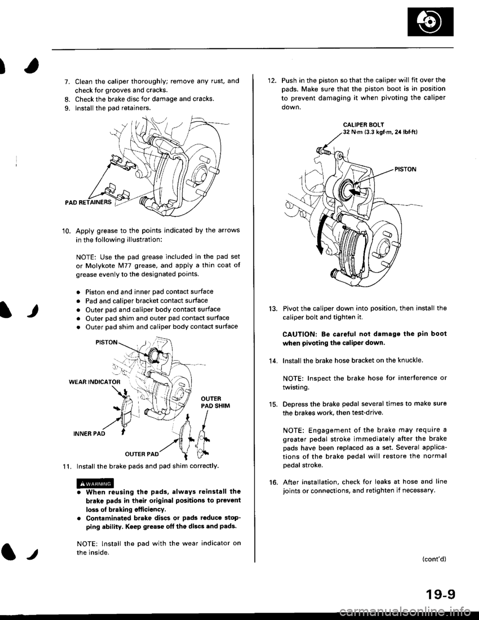
10. Apply grease to the points indicated by the arrows
in the following illustration:
NOTE: Use the pad grease included in the pad set
or Molykote Nl77 grease, and apply a thin coat of
grease evenly to the designated points.
o Piston end and inner Dad contact surface
. Pad and calioer bracket contact surface
. Outer pad and caliper body contact surface
. Outer pad shim and outer pad contact surface
. Outer pad shim and caliper body contact surface
WEAR INDICATOB
INNER PAD
OUTER PAD
1 1. Install the brake pads and pad shim correctly.
. Whon reusing the pads, always reinstall the
brake pads in their original positions to prevont
loss of braking efticiency.
. Contaminated brake discs or pads teduce stop-
ping ability. Keep grease oft the discs and pads'
NOTE: lnstall the Dad with the wear indicator on
the inside.l.t
'12. Push in the piston so that the caliper will fitoverthe
pads, Make sure that the piston boot is in position
to prevent damaging it when pivoting the caliper
down.
Pivot the caliper down into position, then install the
caliper bolt and tighten it.
CAUTION: Be caretul not damage the pin boot
when pivoting the caliper dowr.
lnstall the brake hose bracket on the knuckle
NOTE: Inspect the brake hose for interference or
twisting.
Depress the brake pedal several times to make sure
the brakes work. then test-drive.
NOTE: Engagement of the brake may require a
greater pedal stroke immediately after the brake
pads have been replaced as a set. Several applica-
tions of the brake pedal will restore the normal
Dedal stroke.
After installation. check for leaks at hose and line
joints or connections, and retighten if necessary.
13.
14.
15.
16.
(cont'd)
19-9
CALIPER BOLTN m (3.3 kgf m,2a lbf.ft)
Page 1165 of 2189
)
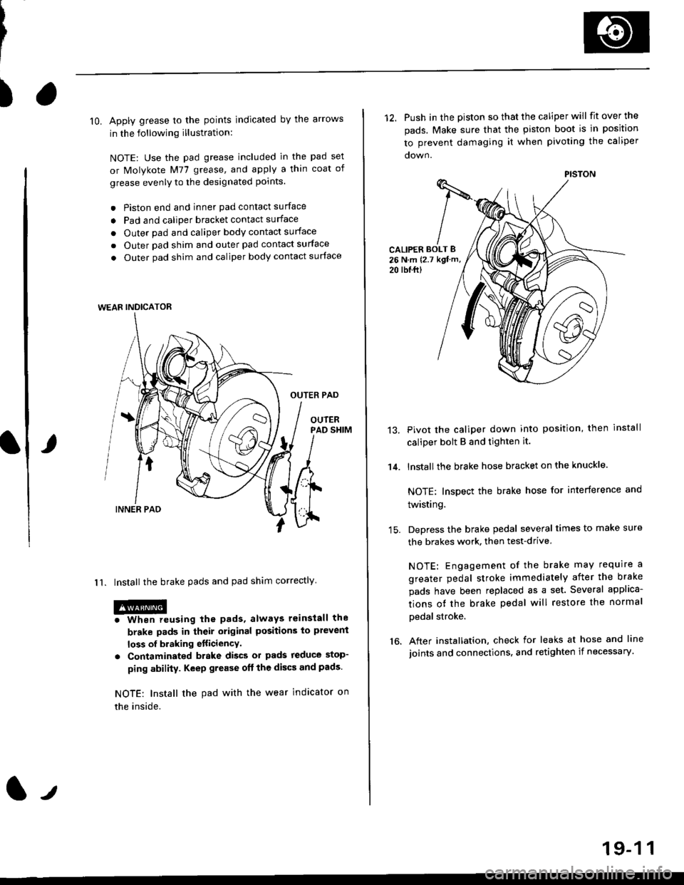
lO. Apply grease to the points indicated by the arrows
in the following illustration:
NOTE: Use the pad grease included in the pad set
or Molykote M77 grease, and apply a thin coat of
grease evenly to the designated points.
. Piston end and inner pad contact surface
o Pad and caliper bracket contact surface
. Outer pad and caliper body contact surface
. Outer pad shim and outer pad contact surface
. Outer pad shim and caliper body contact surface
OUTER PAD
OUIERPAD SHIM
I 1. Install the brake pads and pad shim correctly
@o When reusing the pads, always reinstall the
brake pads in their original positions to plevent
loss of braking etticiencY.
. Contaminated brake discs ol pads reduce stop-
ping ability. Keep grease oft the discs and pads.
NOTE: Install the pad with the wear indicator on
the inside.
WEAR INDICATOR
12. Push in the piston so that the caliper will fit over the
pads. Make sure that the piston boot is in position
to prevent damaging it when pivoting the caliper
CALIPER BOLT B26 N.m {2.7 kgt m,
20 rbl.ftl
14.
13.Pivot the caliper down into position, then install
caliper bolt B and tighten it.
lnstallthe brake hose bracket on the knuckle.
NOTE: Inspect the brake hose for interference and
twisting.
Depress the brake pedal several times to make sure
the brakes work, then test-drive
NOTE: Engagement of the brake may require a
greater pedal stroke immediately after the brake
pads have been replaced as a set. Several applica-
tions ot the brake pedal will restore the normal
pedal stroke.
After installation, check for leaks at hose and line
joints and connections, and retighten if necessary.16.
PISTON
19-1 1
Page 1179 of 2189
I
7.
11.
Clean the caliper thoroughly; remove any rust, and
check for grooves and cracks.
Check the brake disc for damage and cracks.
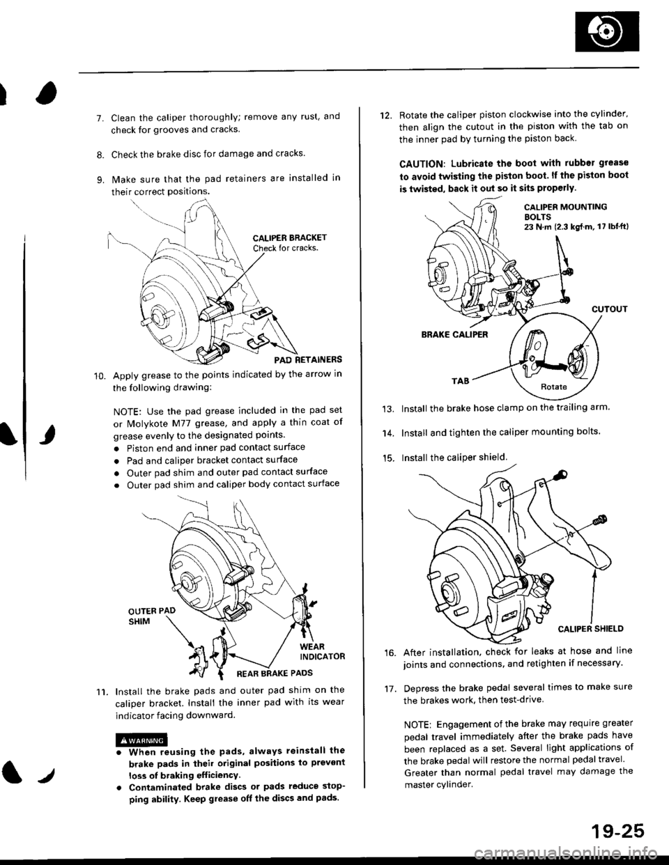
lvlake sure that the pad retainers are installed in
their correct positions.
PAD RETAINERS
Apply grease to the points indicated by the arrow in
the following drawing:
NOTE: Use the pad grease included in the pad set
or lMolykote M77 grease, and apply a thin coat of
grease evenly to the designated points.
. Piston end and inner pad contact surface
. Pad and caliper bracket contact surface
. Outer pad shim and outer pad contact surface
. Outer pad shim and caliper body contact surface
lnstall the brake pads and outer pad shim on the
caliper bracket. Install the inner pad with its wear
indicator facing downward.
@iwhen reusing the pads, always reinstall the
brake pads in iheil original posiiions lo prevont
loss ol braking efficiency
. Contaminaled brake discs or pads reduce stop-
ping ability. Keep grease off the discs and pads.
t./
19-25
12. Rotate the caliper piston clockwise into the cylinder'
then align the cutout in the piston with the tab on
the inner pad by turning the piston back
CAUTION: Lubricate ths boot with rubber grease
to avoid twisting the piston boot. lf the piston boot
is twisted, back it out so it sits properly.
CALIP€R MOUNTINGBOLTS23 N,m {2.3 kg{.m, 17 lbt'ft)
13.
14.
15.
CUTOUT
BRAKE CALIPER
Install the brake hose clamp on the trailing arm.
Install and tighten the caliper mounting bolts.
Install the caliper shield.
After installation. check for leaks at hose and line
joints and connections, and retighten if necessary.
Depress the brake pedal several times to make sure
the brakes work, then test-drive
NOTE: Engagement of the brake may requrre greater
pedal travel immediately after the brake pads have
been replaced as a set. Several light applications of
the brake pedal will restore the normal pedal travel.
Greater than normal pedal travel may damage the
master cylinder.
16.
17.
Page 1193 of 2189
Brake Hoses/Lines
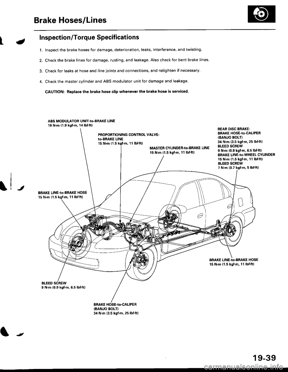
LJ
Inspection/Torque Specifications
t. Inspect the brake hoses for damage, deterioration, leaks, interference, and twisting.
2. Check the brake lines for damage, rusting. and leakage. Also check for bent brake lines.
3. Check for ieaks at hose and line ioints and connections, and retighten if necessary'
4. Check the master cylinder and ABS modulator unit for damage and leakage
CAUTION: Replace tho brake hose clip whenev€r the brake hose is serviced.
ABS MODULATOR UNIT-Io-BRAKE l-lNE19 N.m (1.9 kgf.m, 14lbl.ftl
PROPOBTIONING CONTROL VALVE.io-BRAKE LINEl5 N.m (1.511 tbf.ftl
MASTER CYLINDER-Io-BMKE LINE
15 N.m (1.5 ksrf.m, 11 lbf'ft)
REAR DISG BRAKE:BRAKE HOSE-to4ALlPER
{BANJO BOLT}34 N.m (3.5 kgtm,25 lbf ftlBLEEO SCREW9 N'm (0.9 kgf.m, 6.5 lM.ftlBRAKE LINE-to-WHEEL CYLINDER15 N.m (1.5 kgl.m, 11 lbf.ftlBLEED SCREW7 N.m {0.7 kst m, 5 lbf,ttl
JBRAKE LINE-io-aRAKE HOSE15 N.m {1.511 tbtft)
BRAKE LINE-Io-BRAKE HOSE15 N.m (1.5 kgt.m, 11 lbf'ft)
(BANJO BOLT}3,1 N.m 13.5 kgf.m, 25 lbf.ft)
J
19-39