Page 219 of 2189
Piston RingsCrankshaft Oil Seal
Alignment (cont'dl
TOP RING ---.>
SECOND RING >
MARK
,a-)
/\_4
o,.r^o( qffi<--sPACER
\Z-.
v
Rotate the rings in their grooves to make sure theydo not bind.
Position the ring end gaps as shown:
DO NOT position any ring gapat piston thrust surfaces.
DO NOT position any ring gapin line with the piston pin hole.OIL RING GAP
SECOND RING GAP
Approx.90
TOP RING GAP
7-22
Installation
The seal surface on the block should be dry.Apply a light coat of oil to the c.ankshaft and tothe lip of the seal.
1. Drive the crankshaft oil seal squarely into the right
side cover using the special tools.
HANDLE DRIVER07749 0010000
seal with thepan number sidefacing out.
Confirm that the clearance is equal all the way
around with a feeler gauge.
Clearance:0.5 - 0.8 mm (0.02 - 0.03 inl
NOTE: Refer to page 8-14 for installation of the oilpumo side crankshaft oil seal.
,(
\
Page 222 of 2189
81642 ongin€:
D16Y5, Dl6fr, Dl6Y8 engines:
k9l.m,
RIGHT SIDE
DOWEL PINS
6 x 1.0 mm11 N.m {1.1a rbf.ft)
OOWEL PIN
9. Apply liquid gasket to the oil pump mating surtace
of the block, then install the oil pump on the cylin-
der block.
Apply grease to the lips of the oil seals.
Thgn, align the inner rotor with the crankshaft and
install the oil pump. When the pump is in place,
clean any excess grease off the crankshaft. Check
that the oil seal lips are not distorted.
B16A2 ongino:
Apply liquid gasket alongthe broken line,
Dl6Y5, Dl6Y7, Dt6Y8 ongino3:
Apply liquid gasket
along the broken
OIL PUMP }{OUSING
{cont'd)
7-25
Page 223 of 2189
CrankshaftOil Pan
Installation (cont'd)
NOTE:
. Apply a light coat of oil to the crankshaft and iothe lip of seal.. Use new O-rings and apply oil when installingthem.
10. lnstallthe oil screen.
816A2 engine:
6 x 1.O mml l N'm (1 .1 kgl.m,8 tbt.Irl
,.//
{ / cor*rt(..ao Replace.
t(^^
11 N.m 11 .1 kgf.m,a lbl'ltl ,/.rB tbt4tl /
*P/
& ^/t
O.RINGReplace.
OtL PutitP
D16Y5, D16Y7, D16Y8 engines:
24 N.m (2.4 kgf.m,'17 lbl.fr)
kgf.m,
OIL SCREEN
6 x 1.0 mm1 1 N.m {1 .1 kgf.m,
6x1.0mm11 N.m {1.18 tbt.rr)
I
Ia lbf.fr)
DOWEL PIN
rT
lle/ OIL PUMP6 x 1.0 mm11 N.ml l.1 kgf'm, a lbf.frl
7-26
Installation
D16Y5, Dl6Yg engines:
1. Install the oil pan gasket on the oil pan.
OIL PANGASKETReplace.
OIL PAN
I
Page 226 of 2189
Oil Seals
lnstallation
NOTE:
. Engine removal is not required.
. The crankshaft oil seal housing should be dry.
Apply a light coat of grease to the crankshaft and to
the lips of the seals.
1. Using the special tool, drive in the timing pulley-
end seal until the driver bottoms against the oil
pump.
When the seal is in place, clean any excess grease
off the crankshaft and check that the oil seal lip is
not distorted.
07947 -S800200
lnstall seal with thepart number sadefacing out.
I
2. Measure the flvwheel-end seal thickness and the oil
seal housing depth. Using the special tool. drive the
flywheel-end seal into the rear cover to the point
where the clearance between the bottom of the oil
seal and the right side cover is 0.5 - 0.8 mm (0.02 -
0.03 in) (see page 7-23).
NOTE: Align the hole in the driver attachment with
the Din on the crankshaft.
DRIVER ATTACHMENT0794a-s800101lnslall seal with thepart number sidefacing out.
DRIVER07749-0010000
7 -29
Page 241 of 2189
22. Installthe oil pump on the cylinder block.
Apply grease to the lip ot the oil pump seal.
Then. install the oil pump onto the crankshaft.
When the pump is in place, clean any excess grease
off the crankshaft and check that the oil seal lip is
not distorted.
81642 engine:
8 x 1.25 mm6x1.Omm
24 N.m (2.i4 kg[.m,17 tbl.trl
11 N.m {1.1 kg{.m,8 rbt ft)O.RI GReplace.
DOWEL PINS
GASKETReplace.
OIL SCREEN
6x1.0mmrl N.m {1.1 kgf'm,I tbf.ftl
D16Y5, D16Y7. D16Y8 enginos:
OOWEL PIN
6x1.0mm11N'm (1.1 kgf m'
O.RINGReplace.
DOW€L PIN
GASKETReplace.
6x1.0mm
6 x 1.0 mm '11 N'm {1 1 kgf'm,
11 N.m (1.1 kgf.m, I lbf ftl
8 lbf.ft)
!o
8-15
lnstall the oil screen.
Install the oil pan (see pages 7-26 or 7-27).
NOTE: Clean the oil pan gasket mating surfaces.
Page 1473 of 2189

Troubleshooting
ll.
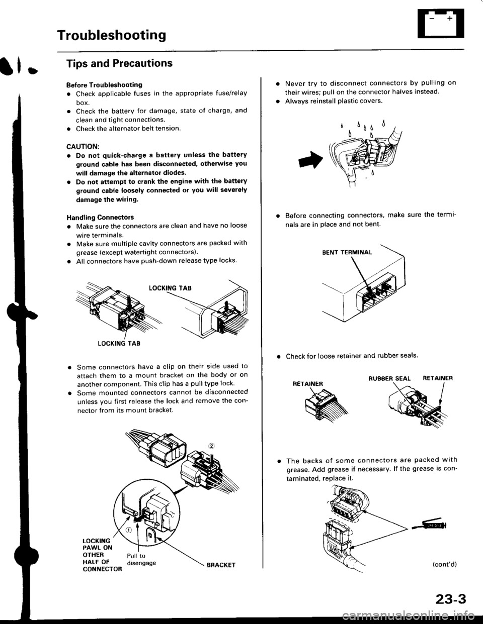
Tips and Precautions
Bef ore Troubleshooting
. Check applicable fuses in the appropriate fuse/relay
box.
. Check the battery for damage, state of charge, and
clean and tight connections.
. Check the alternator belt tension.
CAUTION:
. Do not quick-charge a battery unless the battery
ground cable has been disconneqted, otherwise you
will damage the alternator diodes.
. Do not attempt to crank the engine with the battery
ground cable loosely connecled or you will severely
damage the wiling,
Handling Connectois
. Make sure the connectors are clean and have no loose
wire terminals.
. Make sure multiple cavity connectors are packed with
grease (except watertight connectors)
. All connectors have push-down release type locks.
Some connectors have a clip on their side used to
attach them to a mount bracket on the body or on
another component. This clip has a pulltype lock.
Some mounted connectors cannot be disconnected
unless you first release the lock and remove the con-
nector from its mount bracket.
LOCKINGPAWL ONOTHERHALF OFCONNECTOR
Pull todrsengage
LOCKING TAB
BRACKET
Never try to disconnect connectors by pulling on
their wires; pull on the connector halves instead
Alwavs reinstall plastic covers.
Before connectang connectors,
nals are in place and not bent.
make sure the terml-
. Check for loose retainer and rubber seals.
RETAINER
The backs of some connectors are packed with
grease. Add grease if necessary. lf the grease is con-
taminated, replace it.
(cont'd)
23-3
Page 1829 of 2189

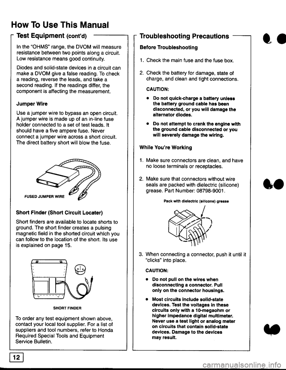
In the "OHMS" range, the DVOM will measure
resistance between two points along a circuit.
Low resistance means good continuity.
Diodes and solid-state devices in a circuit can
make a DVOM give a false reading. To check
a reading, reverse the leads, and take a
second reading. lf the readings differ, the
component is affecting lhe measurement.
Jumper Wire
Use a jumper wire to bypass an open circuit.
A iumper wire is made up ot an in-line fuse
holder connected to a set of test leads. lt
should have a five amoere fuse. Never
connect a jumper wire across a short circuit.
The direct battery short will blow the fuse.
Short Finder (Short Circuit Locater)
Short finders are available to locale shorts to
ground. The short tinder creates a pulsing
magnetic field in the shorted circuit whlch you
can follow to the location of the short. lts use
is explained on page 15.
SHORT FINDER
To ordei any test equipment shown above,
contact your local tool supplier. For a list of
suppliers and tool numbers, refer to Honda
Required Special Tools and Equipment
Service Bulletin.
How To Use This Manual
Test Equipment (cont'd)
oa
Troubleshooting Precautions
Before Troubleshooting
1. Check the main fuse and the fuse box.
2. Check the battery for damage, state of
charge, and clean and tight connections.
CAUTION:
. Do not quick-charge a battery unlers
the battery ground cable has been
disconnected, or you will damage the
alternator diodes.
. Do not attempt to crank the engine wlth
the ground cable disconnected or you
will severely damage the wiring.
While You're Working
1. Make sure connectors are clean, and have
no loose terminals or receptacles.
2. Make sure lhat connectors without wire
seals are packed with dielectric (silicone)
grease. Part Number: 08798-9001 .
Pack wllh dlelectrlc (sillcons) greass
When connecting a connector, push it until it"clicks" into place.
Do not pull on the wires when
disconnecting a connector. Pull
only on the connector houslngs.
Most circuits Include solid-state
devlces. Test the voltages In these
circuits only with a lo-megaohm or
higher impedance digital multlm6ter.
Never use a test light or analog meter
on chcuits that contain solld-state
devices. Damage to the devices
may result.
oo