Page 404 of 2189
L
I
(From page 11-134)
lsrhere approx.0.5 - 0.9 ko?
Chock for an open or 3hort in the
TP 3en30r:Measure resistance between the
TP sensor 3P connector terminalsNo. 2 and No. 3 with the throttle
tully closed.
ls there approx.4.5 k0?
Check for .n opon in th€ ECM/
PCM (TPS lino):1. Reconnect the TP sensor con-nector.2. Turn the ignition switch ON {ll).
3. Measure voltago between Cl8
terminal and C27 terminal on
the ECM/PCM conneclor.
Sub.lltut. . known-good ECM/
PcM lnd r.chock. ll pr6cribod
vohago b now lvallabla, aeplrca
tho originrl ECM/PCM,
ls there approx. 0.5 V when the
throttle is fully closed and
approx. 4.5 V when the throttle
is fully open€d?
Ropair ahort in th. wiro b€{weenECM/FCM lC18l .nd TP ..n.o].
TP SENSOR 3P CONNECTOR
Terminal side ol male terminals
ECM/PCM OONNCCTOR C (31PI
Wire side oI female terminals
.1,
11-135
Page 408 of 2189

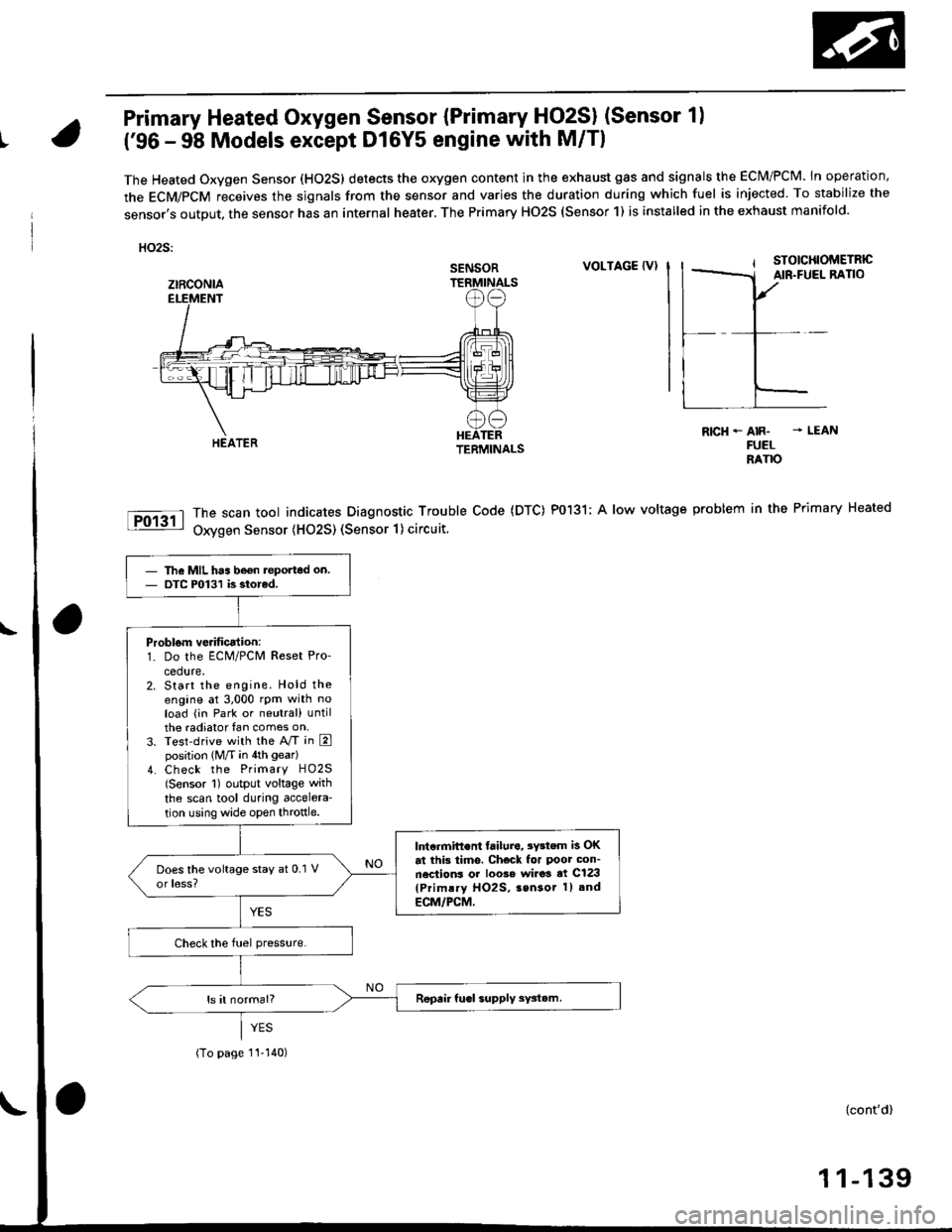
Primary Heated Oxygen Sensor {Primary HO2SI (Sensor 1)
t('96 - 98 Models except Dl6Y5 engine with M/Tl
The Heated Oxygen Sensor (HO2S) detects the oxygen content in the exhaust gas and signals the ECM/PCM. In operation,
the ECM/PCM receives the sjgnals from the sensor and varies the duration during which fuel is injected To stabilize the
sensor,s output, the sensor has an internal heater. The Primary HO2S (Sensor 1) is installed in the exhaust manifold.
HO2S:
VOLTAGE {VI
The scan tool indicates Diagnostic Trouble Code (DTC) P0131; A low voltage
Oxygen Sensor (H02S) (Sensor 1) circuit.
R|cH-AIR- - LEANFUELRANO
problem in the Primary Heated
SENSOR
ztRcoNlA
The MIL has be€n teported on.DTC P0131 is siorcd.
Problom verificalion:1. Do the ECM/PCM Reset Pro'
cedure.2. Start the engine. Hold theengine at 3,000 rpm with noload (in Park or neutral) untilthe radiator fan comes on,3. Test-drive with the A/T in Eposition (M/T in 4th gear)
4. Check the Primary HO2S(Sensor 1) output voltage with
the scan tool during accelera-
tion using wide open throttle.
lntcrmift€nt failura, 3Y3tem is OKat this tims. Check for Poor con-nections or loo3e wi.o3 at C123(Primlry HO2S, 3sn3or 1) and
ECM/PCM,
(To page 1I-140)
{cont'd)
1 1-139
Page 409 of 2189
PGM-FI System
(From page 11-139)
Check for a shon in the HO2S:1. Turn the ignition switch OFF.2. Disconnect the Primary HO2S(Sensor 1) 4P connector.3. Start the engine and let it idle.4. Check the Primary HO2S(Sensor 1)output voltage withthe scan tool,
Does it stay at 0.1 V or less?
Check for a short in lhe wire(PHO2S linel:1. Turn the ignition switch OFF.2. Disconnect the ECM/PCM con-nector D ('l6P).
3. Check for continuity betweenthe Primary HO2S lsensor 1)4P connector terminal No. 1and body ground.
Repair short in lhe wire b6tw6enECM/rcM (D7) and Primary llO2S{Sensor 1}.
Substitute a known-good ECM/PCM and recheck. ll symptom/indication goes awry, replaco theoriginal ECM/PCM.
Primary Heated Oxygen Sensor (Primary HO2S) (sensor 1l
('96 - 98 Models except Dl6Y5 engine with M/T) (cont'dl
PRIMARY HO2S lsonsor 1l ,tP CONNECTOR lC123l
Wire side of female terminals
11-140
Page 410 of 2189

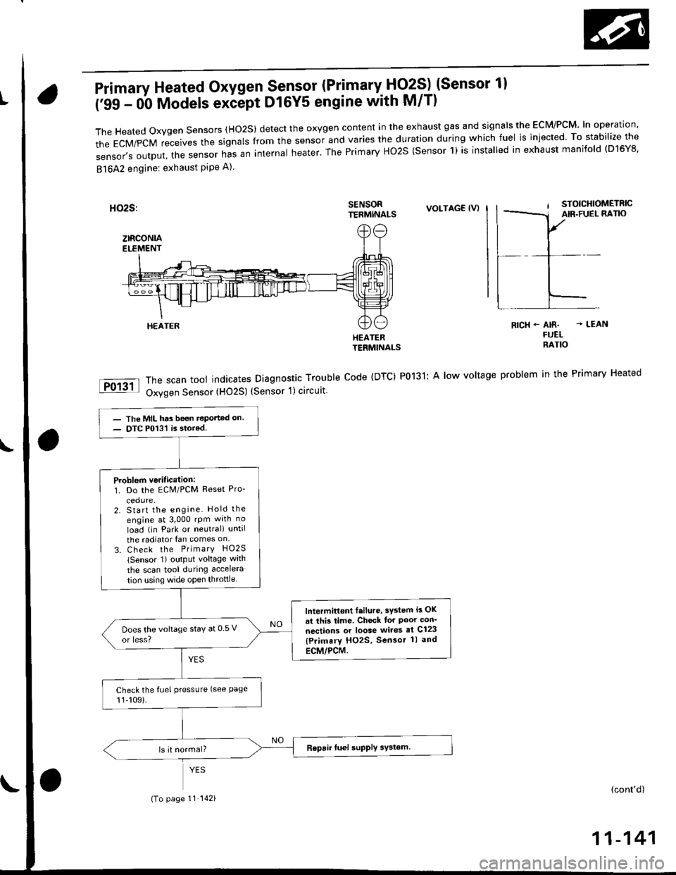
Primary Heated Oxygen Sensor (Primary- Fjq?S) (Sensor 1l
('99 - 0b Models exiept D16Y5 engine with M/T)
TheHeatedoxygensensors(Ho2S)detecttheoxygencontentintheexhaustgasandsigna|stheEcM/PcM'|noperation,
the EcM/pcM receives the signars from the sensor and varies the duration during which fuel is injected. To stabilize the
sensor,soutput,thesensornasaninternaIheater.ThePrimaryHo2S(sensorl)isinsta|ledinexhaustmanifo|d(D16Y8.
81642 engine: exhaust PiPe A)
SENSORTERMINALSVOLTAG€ (VI
HEATERTERMINALS
The scan tool indicates Diagnostic Trouble Code (DTC) P0131: A low voltage
Oxygen Sensor (HO2S) (Sensor 1) circuit
RICH+ AIR- - LEANFUELRATIO
problem in the Primary Heated
HEATER
- The MIL has been t€Ported on.- DTC P013'l is stored.
Problem veritication:1. Do the ECM/PCM Reset Pro-
2. Start the engine. Hold the
engine at 3,000 rpm wrth no
load (in Park or neutral) until
the radiator fan comes on
3. Check the PrimarY HO2S
lSensor 1) output voltage wath
the scan tool during accelera
tion using wide open throttle
lntermittont f.ilure, 3ystem i3 OK
at thi3 time. Check tor Poor con'
nections or loose wires el C123
{Primary HO2S, Sensor 1) and
ECM/PCM.
Does the voltage stay at 0 5 v
or less?
Check the fuel pressLlre (see Page11,109).
(To page 11 142)(cont'd)
11-141
Page 411 of 2189
PGM-FI System
Primary Heated Oxygen Sensor (Primary HO2SI (Sensor 1)
('99 - 00 Models except Dl6Y5 engine with M/T) (cont'd)
PRIMARY HO2S {S€oror 1} 4P CONNECTOR lc123l
PHO2S f----l,wHl_l:-f;-l
0ffi
_L
Wire side of female terminals
(From page 11 141)
Chock fo. a shori in the HO2S:1. Turn the ignition switch OFF.2. Disconnect the Primary HO2S(Sensor 1i 4P connector.3. Stan the engine and let it idle.4. Check the Primary HO2S(Sensor 1) output voltage withthe scan tool.
Does it stay at 0.5 V or less?Roplaco the HO2S (Sensor 1).
Check tor a short in the wire{PHO2S linel:1. Turn the ignition switch OFF.2. Disconnect the EcltI/PcM con-nector C {31P).3. Check for continuity betweenthe Primary HO2S lsensor 1)4P connector terminal No. 1and body ground.
ReDair shorl in the wi.e betweenECM/PCM (Cl61 and PrimaryHO2S (Sercor 11.
Substitute a known-good ECM/PCM and recheck. lf symptom/indication goes away, replace theoriginal ECM/PCM.
11-142
Page 415 of 2189

PGM-FI System
Itil-"w Heated Oxygen Sensor (primary HO2S) (sensor 1l(Dl6Y5 engine with M/Tl
The scan tool indicates Diagnostic Trouble Code (DTC) p1162: A malfunction in the primary Heated OxygenSensor (Primary HO2S) (Sensor 1) circutt.
Doscription
The Primary Heated orygen sensor (Primary Ho2s) {sensor 1) operates over a wide airlfuel range. The primary Ho2S(Sensor 1) is installed in the exhaust manifold.
SEI{SORELEMENT
SENSORTERMINALS
ECM CONNECTOR C (31PIPRIMARY HO2S(SENSOR 1)8PCONNECTOR {Clir5)
female terminalsof femaleterminals
NOTE: lf DTC Pl162 is stored at the same time as DTC Pl167, troubteshoot DTC p1162 first, then recheck for DTC p1167.
(To page 11-147)
- lh6 MIL hes b6on reDorted on.- DTCPl162 ir 3tored.
Problom v6rificationi1. Do the ECM Reset Procedure.2. Start the engine.3. Wait at least tlvo minutes.
Test drive tor several miles withthe transmission in 3rd gear. Holdthe engine speed at 1,500 rpm.
ls DTC P1162 indicatod?
Intermittent tailuro, systom is OKat this timo. Check tor poor con-nections or loose wires at C145(Plimr.y HO2S, Senso. t) andECM,
ls DTC P1162 indicated?
Chock for an open in the wire(lP+ lins):1. Turn the ignition switch OFF.2. Disconnect ECM connector C{31P) from the ECM.3. Disconnect the 8P connectorfrom the Primary HO2S {Sen-sor 1).4. Check for continuity betweenthe Primary HO2S (Sensor 1)8P connector terminal No. 7and ECM connector terminalc23.
Repair open in the wire betwaonECM (C231 end Prim.ry HO2Slsen3or l).
Inspect lor poor terminal to termi-nal contact at the Primary HO2Slsensor 'l I connoctor and ECM.It terminal contect is OK, roplacelh6 Primrry HO2S {Sensor 1}.
11-146
Page 416 of 2189

Check the ECM input vottage {lP-/
VS- lino):1. Turn the ignition switch OFF.
2 Turn the ignition switch ON (ll)
3. Measure voltage between
ECM connector terminals C24
Ch.ck the ECM:
1. Turn the ignition switch OFF
2. Disconndct ECM connector C
{31P){rom the ECM.
3. Check lor continuity between
body ground and ECM con
nector terminal C24
ls there more than 0.5 V?
- Repair open in the wire
betw€en ECM {C2{l and Pri-
ma.y HO2S {S€nsor 1 l.- Substitute a known-good ECM
and recheck. It symptom/indi
cation goes away. replace the
odginal ECM.
Check to. r short in the wi.e {lP-/
VS- lin6l:1. Disconnect the 8P connector
from the Primary HO2S lsen-
sor 1).2. Check tor continuity between
body ground and ECM connec-
tor terminal C24
Ropair short in the wire bstween
the Primary HO2S lsensor 1) and
ECM (C24).
Check the ECM output voltage
{VS+ linel:N4easure voltage between ECM
connectorterminals C25 and D11.
Check for a short in the wire (VS+
line):1. Turn the ignition switch OFF.
2. Disconnect ECM connector C
{31P) Irom the ECM.
3. Check {or continuity between
body ground and ECM con
nector terminal C25.
ls there mote than 0.5 V?
ECM CONNECTORS
lFrom page'11-146)c (31PlD {15P)
tP-/vs- tREolfemale termrnals
sG2(GRN/BLKI
(cont'd)
11-147
I23a68910
111213la15t6'171622
232a25272a2930
O rP-/vs-:Z taeot
,l23a55I910
1112131a151617t822
232125212AE30
0) {REDr
23a518910
l11213ta'15't6171822
2321E272A2930
[]) vs*I rwsrt
(To page 11- 148)(To page 11 148)
Page 417 of 2189

PGM-FI System
Primary Heated Oxygen Sensor (Primary HO2SI (sensor l)
(Dl6Y5 engine with M/T) (cont'd)
(From page 1l-147)(From page 11 147)
(To page 11 149)
{GRN/BLK}
(GRN/8I-K}
(To page 11-149)
11-148
Substitute a known-good ECMand rechock. tf symptom/indicr-tion goes away, replace the origi-nalECM.
Check for a short in the wire llP+lin6):1. Disconnect the 8P connectorIrom the Primary HO2S (Sen-
sor 1).2. Check tor continuity betweenbody ground and ECM connec-tor terminal C25.
Repair short in the wiro botweenthe Primarv HO2S {Sensor 1} andECM {C25}.
Replace th€ Primary HOzS {Sen-sor 11.
| 2 3ra1a9to
tl 12t516111a
p ffi;r, w''.""i0"or.I lemate lerml
ls there more than 5.0 V?check the EcM:1. Turn the ignition switch OFF.2. Disconnect the 8P connectorfrom the Primary HO2S (Sen-
sor 1).3. Turn the ignition switch ON (ll).4. Measure voltage between ECN4connector C25 and D11.
ls there more than 5.0 V?
Check the ECM input voltage llP-/vS-linel:1. Start the engine. Hold theengine at 3,000 rpm with noload (transmission in neutral)untilthe radiator fan comes on,then let it idle.2. Measure voltage between ECMconnector terminals C24 andDt1.
Subslitute a known-good ECMand rgcheck. It symptom/indica-tion goes away, repl.ce the origi-nal ECM.
ls there 2.6 2.8 V?Check th6 ECM output voltage(VS+ linel:Measure voltage between ECMconnector terminals C25 and D11.
7a9t0It 12t3t6'11ta
VS+{WHT}sG2
235
,9 ,101l12
l3'tat515
1 2i35a9t0't2'ttt5ttrl22
VS+{WHT)sG2
23
6lt9ll1315