1996 HONDA CIVIC engine ground
[x] Cancel search: engine groundPage 976 of 2189

Fluid Level
l.Checking/Changing
CAUTION: while chscking and changing, be sure not to
allow dust and other toreign particles to ent€l inlo the
transmission.
Checking
NOTE: Check the fluid level with the engine at normal
operating temperature (the radiator fan comes on).
'1. Park the vehicle on the level ground. Turn oft the
engrne.
2. Remove the dipstick (yellow loop) from the trans-
mission, and wipe lt with a clean cloth.
NOTE: Check the transmission fluid 50 to 90 sec-
onds after shutting off the engine.
3. Insert the diDstick into the transmission.
DIPSTICK (YELLOW LOOPI
Remove the dipstick and check the fluid level.
should be between the uDDer and lower mark.DIPSTICK
5. lf the level is below the lower mark, add fluid into
the filler hole to bring it to the upper mark. Use
Genuine Honda CW Fluid only.
6. Insert the dipstick into the transmission.
14-299
Changing
1. Bring the transmission up to normal operating tem-
perature (the radiator fan comes on) by driving the
vehicle. Park the vehicle on the level ground, and
turn off the engine.
2. Bemove the drain plug, and drain the CVT fluid.
NOTE| lf a cooler flusher is to be used, see page 14-
352 and 14-353.
Reinstall the drain plug with a new sealing washer,
then refill the transmission with Genuine Honda
CVT Fluid to the upper mark on the dipstick.
Automatic Transmission Fluid CaPacity:
3.9 i (4.r US qt. 3.4 lmp qt) 8t chlnging
6.4 I (6.8 US qt, 5.6 lmp qt) 8t ov€lhaul
Rscommended Automatic Transmission Fluid:
Genuine Honda CVT Fluid-
Use Genuine Honda CW fluid only. Using other flu-
ids can affect transmission operation and may
reduce transmission liJe.
Change Interval:
Normal Condition: 30, 000 miles 148,000 km)
Severe Condition: 30,000 miles (48,000 km), but it
you drive at high sPeeds in high
t90"F (32'C) and abovol temper-
atures, the ttansmission fluid
should be changed evsrY 15,000
miles 124,000 km).
{-]lr
ORAIN PLUG18 x 1.5 mma9 N.7n (5.0 kgl.m, 36 lb{'ftl
SEALING WASHERReplace.
Page 981 of 2189
Transmission
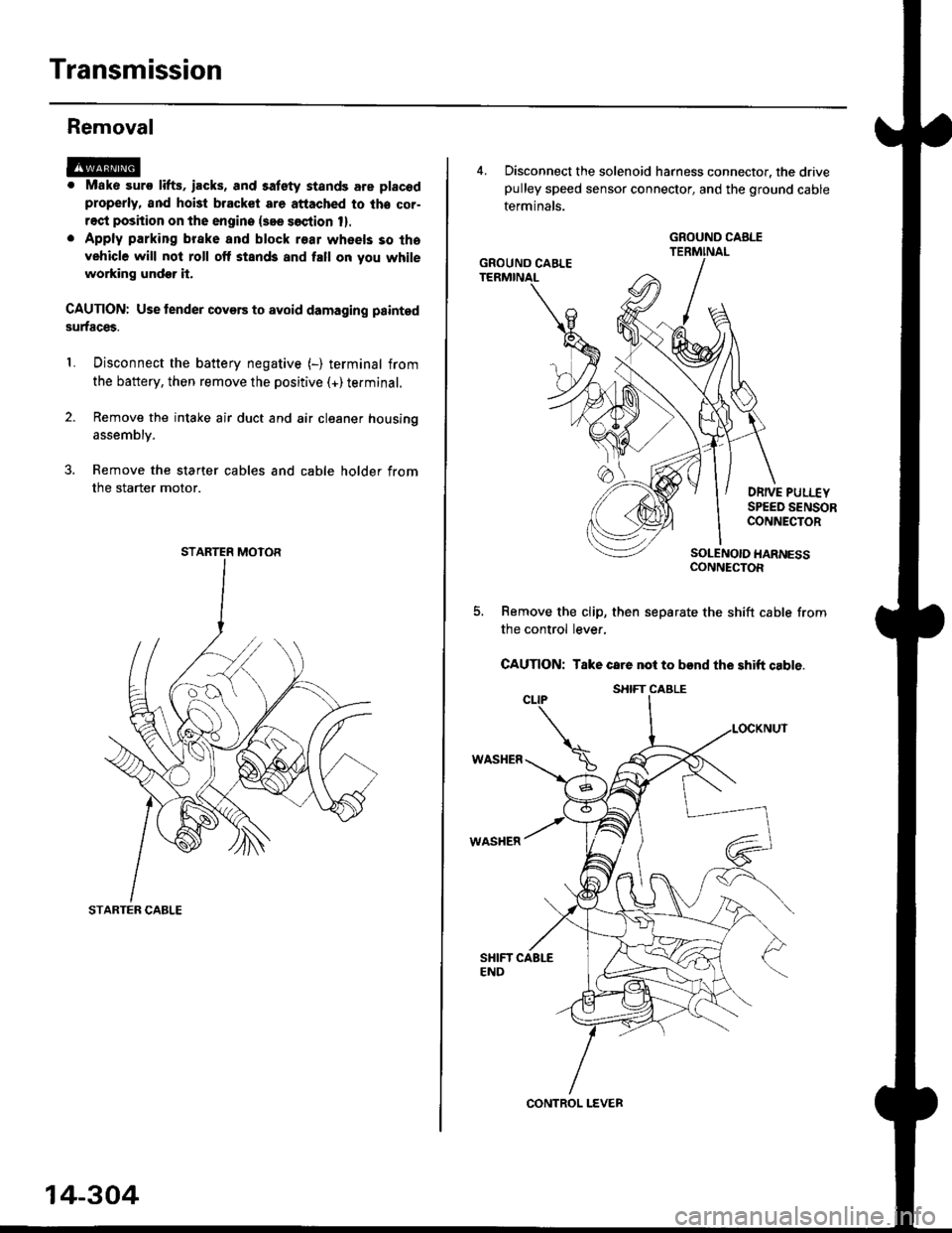
Removal
@. Mako suro lifts. iacks, and satety stands are placod
properly, and hoi3t bracket are attached to lhe cor-
rect position on the engine {see soction 1}.
. Apply parking brake and block r€ar wheels so tha
vehicle will not roll off stands and fall on you while
working undor it.
CAUTION: Use tender covers to avoid damaging painted
surfaces.
Disconnect the battery negative (-) terminal from
the battery, then remove the positive (+)terminal.
Remove the intake air duct and air cleaner housing
1.
assembly.
3. Remove the starter cables and cable holder from
the starter motor.
STARTER CABLE
STARTER MOTOR
14-304
4, Disconnect the solenoid harness connector, the drivepulley speed sensor connector, and the ground cable
terminals.
DRIVE PULI.-EYSPEED SENSORCONNECTOR
SOLENOIO HARNESSCONNECTOR
Remove the clip, then separate the shift cable from
the control lever,
CAUTION: Take care not to bend the shift cable.
WASHER
WASHER
GROUND CABLE
GROUND CAELE
CONTROL LEVER
S}IIFT CABLE
Page 1027 of 2189

22. Install the shift cable end on the control lever, and
install the shift cable on the shift cable bracket'
CAUTION: Take care not to bend the shift cable'
23. lnstall the clip in the direction shown.
LOCKNUT
SHIFI CABLE 29 N m {3.0 kg{ m, 22lblftl
SHIFT CABLEERACKET
WASHERIPLASTIC)
CONTROL LEVER
24, Connect the solenoid harness connector. the drive
pulley speed sensor connector. and the ground
cable terminals.
6x1.0mm12 N.m {1.2 kgf.m.8,7 rbtft)
GROUND CABLETERMINAL 6x1.0mm
GROUNDTERMINAL
12 N.m {1.2 kgf'm,8.7lbtfrl
DRIVE PULLEYSPEED SENSORCONNECTOR
SOLENOID HARNESS
CONNECTOR
25. Connect the starter motor cable on the starter motor.
and install the cable holder.
NOTE: When installing the staner motor cable. make
sure that the crimped side of the ring terminal is
facing out (see section 23).
STARTEB
BMOUNTING NUT
9 N.m (0.9 kgf m,7 lbf ft)
26. Install all removed connectors and clamps'
27. Install the distributor.
28. Install the intake air duct and air cleaner housing
29.
assemDly.
Refill the transmission with the recommended
Genuine Honda CVT Fluid (see page 14-2991
CAUTION: While filling the CvT Fluid, bs surs not io
allow dust and other fotoign particles to entor into
the transmission.
Connect the battery positive (+) terminal first, then
the negative (-l terminal to the battery'
Check the ignition timing (see section 23).
Start the engine. Set the parking brake, and shift the
transmission through all gears three times Check
shift cable adjustment (see page 14-355).
Check the front wheel alignment (see section 18)
Let the engine reach operating temperature (the
radiator fan comes on) with the transmission in lXl
or E position, then turn it off and check fluid level'
Perform the start clutch calibration procedure on
page 14-293.
Road test as described on pages 14-296 and 14-297
30.
31.
34.
36.
STARTER MOTOR
14-351
Page 1160 of 2189
Inspection and Adjustment
Parking Brake
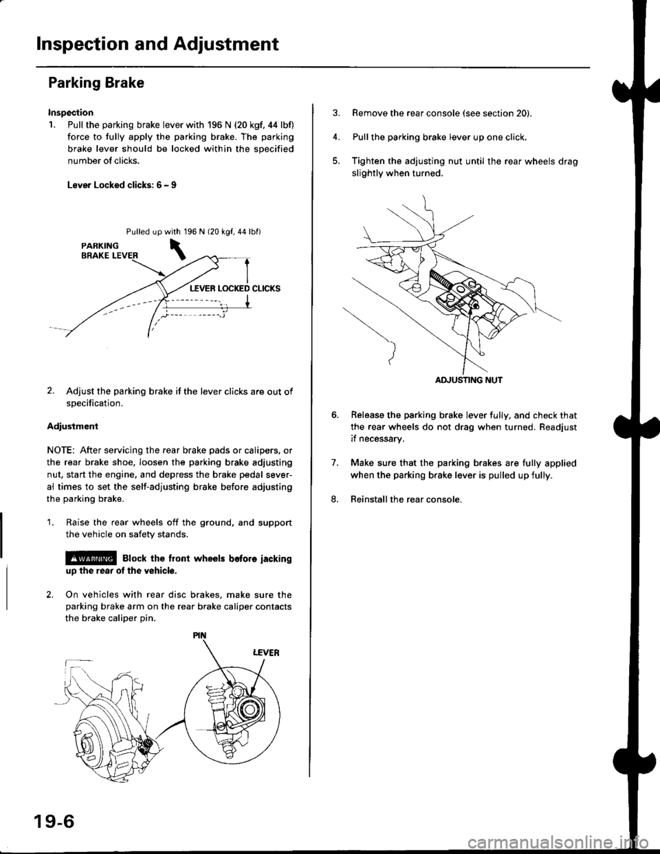
Inspection
1. Pull the parking brake lever with 196 N {20 kgf. 44 lbf)
force to fully apply the parking brake. The parking
brake lever should be locked within the sDecified
number of clicks.
Lever Locked clicks: 6 - I
Pulled up96 N 120 kgf,44lbf)
2. Adjust the parking brake if the lever clicks are out of
specification.
Adiusiment
NOTE: After servicing the rear brake pads or calipers, or
the rear brake shoe, loosen the parking brake adjusting
nut, start the engine, and depress the brake pedal sever-
al times to set the self-adjusting brake before adjusting
the parking brake.
1. Raise the rear wheels off the ground, and support
the vehicle on safety stands.
l@ Elock the front wheels bofore iackinguD the rear ot the v6hicle.
2. On vehicles with rear disc brakes, make sure theparking brake arm on the rear brake caliper contacts
the brake calioer Din.
with 1
\
19-6
Remove the rear console (see section 20).
Pullthe parking brake lever up one click,
Tighten the adjusting nut until the rear wheels drag
slightly when turned.
Belease the parking brake lever fully, and check that
the rear wheels do not drag when turned. Readjust
if necessarv.
Make sure that the parking brakes are fully applied
when the parking brake lever is pulled up fully.
Reinstall the rear console.
7.
8.
ADJUSTING NUT
Page 1211 of 2189
Diagnostic Trouble Code (DTCI
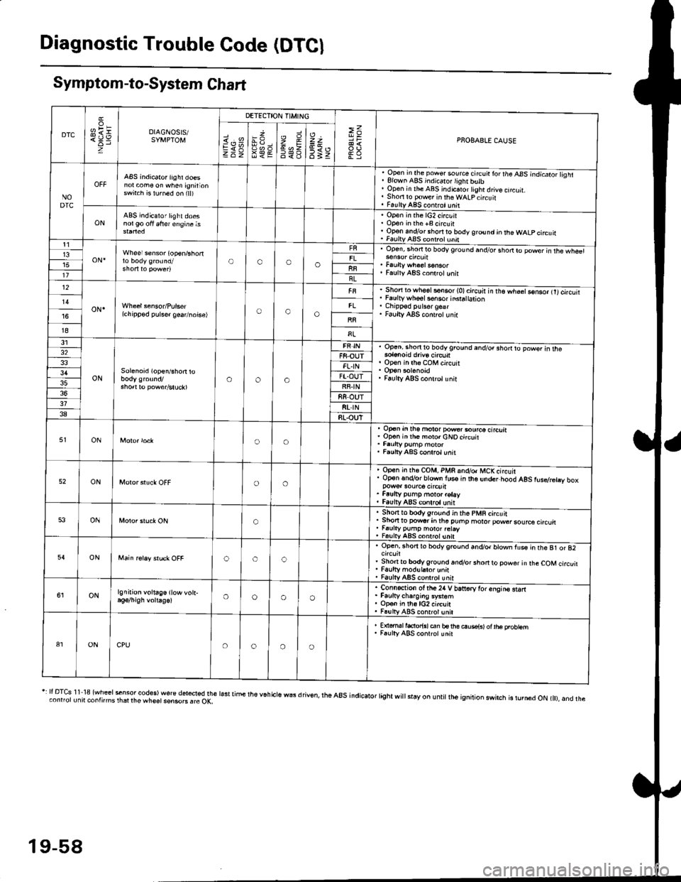
Symptom-to-System Chart
DTC
oH1=DIAGNOSIS/SYMPTOM
DETECTION TIMING
>=PNOBABLE CAUSEi.'sEV98€E
zr\9=6<_6
=t
6tz
NODTC
ABS indicator iighr doesnot com€ on when ignirionswrt.h is lu.ned on (ll)
, Open in the pow€. source circ!ir ror the ABS -.ndicato;l isht. Elown ABS indicalo.lighr butb' Open in rhe ABS indicaror tight drive cncuit.. Shori ro pow€r in theWALpcircuit. FaultyABS contrct!nit
ONABS indicator light doesnol90 oft 6frer engine isOpen in the lG2 circuitOpon in the +B circuirOp€n andlor short ro body ground jn the WALP circuitFaultv AAS coni.ol unnt1
oN.Wheel sensor (op€n/shortOooo13upen, snofiro bodyground and/or shodro power in rhe wh€61
Faulty ABS co.lrctunitllBL12
oN.(chipp€d pulser gea/noise)oao
Short to wh6sls€n6or (O)circuir in t'e.h;;Go-nso, trtcircutiFaulty whsel s€nsor insra|ation
Faulty ABS cont.olunir
I8
31
ONSolenoid (open/shon roaoa
Op.ni shon to bodyground and/o. shorrto powsr in rhe
op€n in lh6 coM circuit
Faulty ABS conlrclunit
32F8-OUTFL.IN3'lFT.OUTRF.IN88 OUT318t rN38RLOUT
ONoo
op€n in tho motor pow€..ourco circliaOp€n inih€ moro.cNOcircuit
Faulty ABS conrrol unit
52ONoo
Open in rh€ COM, PMR 6nd/o. MCKcircuirOp€n.n.Vor blown lus€ in the under hood AgS rusdretry box
Faufty pump moto. rotayfaulv ABS conlrolunit
53ONo
. Sho.tto bodygrou.d in the pMR circuit. Shon to powsr in tha puhp moror pow6rsource circu. r.urty pump motor.etay, FalltyABS contolunit
54ONooc
Open, rhorr ro bodygrcund and/or blown fus€ in the B1 or 82
Shonto body ground.n.Vor short to powor in rhe COM circuitFaulty modul.tor unnFaulty ABS controt unit
ONlgnition voltage (low vott-oooo
. Connection ot the24 V bariorv tor enqins starr. Faurtycharoins system. Op€n in th6lG2 circuit. Fa!lly ABS contrcl unil
81ONCPUoooo
E {€rml facior{sl en bs rhe ouse{sl ot |he probtemF.ulty ABS conrrot unit
r: It DTcs 1 1 18 {wheel sensor codes) wore del*ted the lasr time the v6h cls wEs d riv€n, rhe a8s indicator tight wi
stay on u ntit lh6 ignition swirch is rurn6d oN t), and theconnorunit contnms rhat rhe wheet sensoB . rc OK,
19-58
Page 1215 of 2189
Troubleshooting
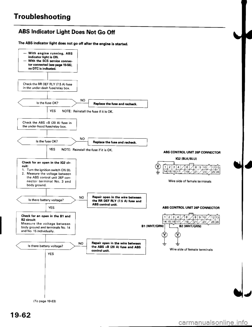
The ABS indicator light does not go off after the engine is started.
- With engine running, ABSindicator light is ON.- With tho SCS sewice connec-to. connected l3oe page 19-561,no DTC is indicated,
Checkthe RR DEF RLY {7.5 A)tusein the under-dash fuse/relay box.
Raphco tha furo and rochack.
Check the ABS +B (20 A) fuse inthe under hood tuse/relay box.
R6pl.ce tho tu3c lnd r.ch.ck.
Chock for an open in the lG2 cir-GUrt:1. Turn the ignition switch ON (lt).2. Measure the voltage betweenthe ABS control unh 26P con-nector terminal No. 3 andbody ground.
Bopair opcn in tha wir. botw.cnth. RR DEF RLY 17.5 Al tus. .ndABS control unit.
Check tor an opon in thG Bl end82 circuit:Measure the voltage betweenbody ground and terminals No. 14and No. 15 individually.
Rrpair opsn in tha wiro t atwa,anthe ABS +B (20 Al fu.r .nd ABScontrol unh.
ls there banery voltage?
1To page 19-63)
ABS Indicator Light Does Not Go Off
YES NOTE: Feinstattthe luse it it is OK.
YES NOTE: Reinsta
the fuse if it is OK.ABS CONTROL UNIT 26P CONNECTOR
IG2IELK/BLUI
Wire side of female terminals
ABS CONTBOL UN]T 26P CONNECTOR
8T IWHT/GRNI
Wire side of temale terminals
19-62
Page 1217 of 2189
Troubleshooting
Wheel Sensor
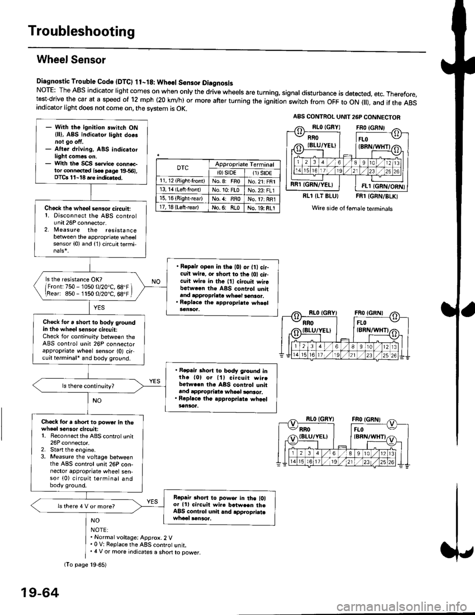
Diagnostic Trouble Gode {DTC) ll-18: Wheol S€n3ol DiagnosisNoTE: The ABS indicator light comes on when only the drive wheels are turning, signal disturbance is detected, etc. Therefore,test-drive the car at a speed of 12 mph (20 krn/h) or more after turning the ignition:witch from OFF to ON fll), and if the ABSindicator light does not come on, the svstem is OK.
0TcAppropriate Terminal(0)srDE11) SrD€r 1, 12 (Right-front)No.8: FRoNo.21: FRI13, 14 (Left-front)No. 10: FLoNo.23: FL115, 16 {Right-rear)No. {: RRoNo. 17: RRl17, 18 (Left-rear)No.6: RLoNo. 19: RLI
RLl (LT BLU}FRl (GRN/BLKI
Wire side ol female terminals
NO
NOTE:. Normal voltage: Approx.2 V' 0 V: Replace the ABS controt unit.. 4 V or more indicates a short to power.
A8S CONTROL UNIT 26P CONNECTOR
RRO
IBLU/YELI
RR1 IGRN/YELIFL1 IGRN/ORN}
- With the ignition switch ON{ll), ABS indicator tighr doe.noi go off,- Aftsr driving, ABS indicatotlight comes on.- With the SCS so.vice connac-tor conn€c,ted {soe pege 19-561,DTCs 11-18 a.e indicrted.
Chock lhe wheol sensor ci.cuit:1. Disconnect the ABS controlunit 26P connector.2. lleasure the resistancebetween the appropriate wheelsensor (0) and (1) circuit termi,
. Reprir op€n in the l0l or {0 cir-cuit wiro, or shon to thc {01 cir-cuit wi.o in thc {11 circuit wircbctween ths ABS control unitand approprieto wheel a6nsor.. R.pl.ce th€ epp.opri.te wheal3€nloa.
ls the resistance OK?
/Frontr 750 - 1050 o/20"C, 68.F \\Rear: 850- 1150 O/20.C, 68"F /
Check toru short to body groundin the wheel senso. circuit:Check for continuity between theABS control unit 26P connectorappropriate wheel sensor (0) circuit terminali and body ground.
. Rapair short to body ground inth6 (0) or lll cilcuit wi..bctwa.n th6 ABS control unitand appropdaie whoel lonsor.. Rep|'c6 tho appropriatc whcelsanlor.
Chock tor a sho.t to powe. in thowheel3en3or circuit:1. Reconnect the ABS control unit26P connector,2. Start the engine.3. Measure the voltage betweenthe ABS control unit 26P con-nector appropriate wheel sen-sor (0) circuit terminal andbody ground.
Ropair rhon to powo. in the l0lor lll circuit wire batw.en th€ABS cont.ol unit and .pplopriatawhccl !€naoa,
ls there 4 V or more?
fio page 19-65)
19-64
Page 1219 of 2189
Troubleshooting
Solenoid
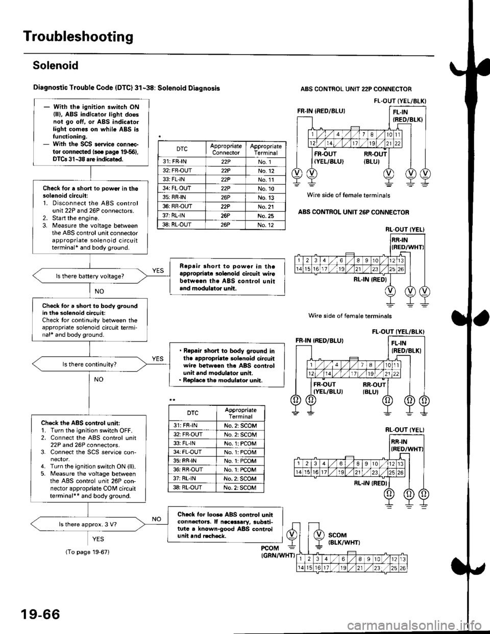
Diagnostic Trouble Code {DTC} 31-38: Solenoid Diagnosis
YES
ABS CONTROL UNIT 22P CONNECTOR
Wire side of female terminals
ABS CONTROL UNIT 26P CONNECTOR
FL.OUT (YEL/ALK)- With the ignition switch ON(lll, ABS indicator light doesnol go oft. or ABS indic.to.light comes on while ABS i3functioning.- With the SCS servico connec-tor connected ls€. pag€ 19-561,DTCa 31-38 are indicstod.
Check for a short lo powor in thosol6noid circuitl1. Disconnect the ABS controlunit 22P and 26P connectors.2. Sta rt the engine.3. Measure the voltage betweenthe ABS control unit connectorappropriate solenoid circuitterminal* and body ground.
Ropri. short to powor in thcappropriate solanoid ci.cuit wirobotw6.n ths ABS cont.ol unitand modulrtor unit.
ls there battery voltage?
Check for a short to body groundin the 3olenoid circuit:Check tor continuity between theappropriate solenoid circuit termi-nal* and body ground.
. Repair short to body ground inlhe .ppropriato solonoid circuitwire betwoan th6 ABS controlunit and modllato. unit.. Replaco the modul.tor unit.
Check th€ ABS control unit:'1. Turn the ignition switch OFF.2. Connect the ABS control unit22P and 26P connectors.3. Connect the SCS service con-
4. Turn the ignition switch ON {ll}.5. Measure the voltage betweenthe ABS control unit 26P con-nector appropriate CONI circuitterminal++ and body ground.
Check for loos€ ABS control unhconnectora. It naceslrry, aub3ti-tutc . known-good ABS controlunit tnd recheck.
ls there approx. 3 V?
DTCAppropriateConnectorAppropriateTerminal
31: FRJN22PNo. 1
32: FR-OUT22PNo.12
33i FL'IN22PNo. 11
34: FL OUT22PNo.10
3s: RRIN26PNo.13
36: RR-OUT22PNo. 21
37: RLIN26PNo.25
38: RL-OUT26PNo.12RL.OUT IYEL}
Wire side of female terminals
DTCAppropriateTerminal
31: FR-lNNo. 2: SCOM
32: FR-OUTNo. 2: SCOM
33i FLINNo. 1: rcOM
34: FL-OUTNo. l: PCOM
35: RR{NNo.1:PCOM
36: RR-OUTNo. 1: rcOM
37rRL'lNNo. 2: SCOM
38: RL-OUTNo. 2: SCOM
RL.OUT (YEL}
19-66
(To page 19-671