Page 491 of 2189

ldle Control System
ldle Speed Setting (cont'dl
Inspeqtion/Adiustment
38 D16Y5 engine whh M/T,'99 - 00 81642 engine
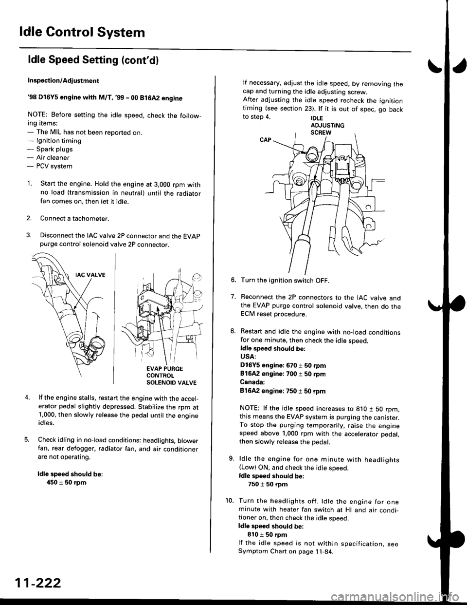
NOTE: Before setting the idle speed, check the follow-ing items;- The MIL has not been reported on.- lgnition timing- Spark plugs- Air cleaner- PCV system
'1. Start the engine. Hold the engine at 3,000 rpm withno load (transmission in neutral) until the radiatorfan comes on, then let it idle.
Connect a tachometer.
Disconnect the IAC valve 2P connector and the EVAPpurge controlsolenoid valve 2P connector.
EVAP PURGECONTROLSOLENOID VALVE
lf the engine stalls, restart the engine with the accel-erator pedal slightly depressed. Stabilize the rpm at1.000, then slowly release the pedal until the engineidles.
Check idling in no-load conditions: headlights, blowerfan, rear defogger, radiator fan, and air conditionerare not operating.
ldl€ speed should be:
450 i 50 rpm
11-222
lf necessary, adjust the idle speed, by removrng lnecap and turning the idle adjusting screw.After adjusting the idle speed recheck the ignitlontiming (see section 23). lf it is out of spec, go backto step 4. |DLE
6. Turn the ignition switch OFF.
7. Reconnect the 2P connectors to the IAC valve andthe EVAP purge control solenoid valve, then do theECM reset procedure.
8. Restart and idle the engine with no-load conditionsfor one minute, then check the idle sDeed.ldle speed should bo:
USA:
D16Y5 engine: 670 i 50 rpm
81642 engine: 700 i 50 rpm
Canada:
81642 engine: 750 t 50 rpm
NOTE: lf the idle speed increases to 8lO t 50 rpm,this means the EVAP system is purging the canister.To stop the purging temporarily, raise the enginespeed above 1,000 rpm with the accelerator pedal,
then slowly release the pedal.
9. ldle the engine for one minute with headlights(Low) ON. and check the idle speed.
ldle speed should be:
750 i 50 rpm
10. Turn the headlights off. ldle the engine for oneminute with heater fan switch at Hl and air condi-tioner on, then check the idle soeed.ldls speed should be:
810 t 50 rpm
lf the idle speed is not within specification, seeSymptom Chart on page 11-84.
Page 492 of 2189

\
I
'98 - 0O D16Y5 ongine with CvT
Adjust the idle speed using a Honda PGM Tester if pos-
sible. lf not, use the following procedure:
NOTE:
. Leave the IAC valve connected.
. Before s€tting the idle speed, check the following
rtems:- The MIL has not been reported on.
- lgnition timing
- Spark Plugs- Air clean€r
- PCV svstem
'1. Connect a tachometer.
2. Stan the engine. Hold the engine at 3,000 rpm w'th
no load (transmission in E or E] position) until the
radiator Jan comes on, then let it idle.
3. Check the idle speed under no-load conditions:
head lights, blower fan, rear defogger, radiator fan,
and air conditioner are not operatlng.
ldlo spaod ehould bo: 700 t 50 rpm
. lf the idle speed is within the specification, the
procedure is comPlete.
. lf the idle sDeed is out of specitication, 9o to step 4'
4. tf the idle speed is 810 1 50 rpm, this means the
EVAP system is purging the canister. To stop the
purging temporarily, raise the engine speed above
l,OO0 rgm with the accelsrator pedal. Slowly release
the pedal. and rscheck the idl€ speed.
. tf the idle speed is within the specificstion, the
Drocedure is comPlete.
. lf the idle sp€ed is out of spocification, go to step 5.
5. Disconnect th€ EVAP purgs control solenoid valve
2P connector.
EVAP PURGECONTROL
6. Remove the cap and turn the idle adiusting screw
1/2-turn clockwise or counterclockwlse
IDLE
7.After turning the idle adjusting screw 1/2-turn, check
the idl€ speed again. lf it is out of spec, turn the idle
adjusting screw 1/2-turn again.
NOTE: Do not turn the idle adjusting screw more
than 1/2-turn without checking the idle speed.
Turn the ignition switch OFF. Reconnect the EVAP
purge control solenoid valve 2P connector' then do
the ECM reset Procedure.
Start the engine. ldle the engine for one minute with
heater fan switch at Hl and air conditioner on, then
check the idle speed.
ldle spaed should be:
810 t 50 rpm (in El or E Posiiion)
lf the idle speed is not within specification, see
Svmptom Chart on Page 11-84.
9.
SOLENOID VALVE
11-223
Page 501 of 2189
Fuel Supply System
Fuel Injectors
Replacement
@ Do not smoke when working on the tuel systgm, Keep gp6n flames away from your work area
'f. Relieve the fuel pressure (see pages 11-230,231J.
2. Disconnect the connectors from thefuel injectors (D16Y7 engine: Remove the air cleaner).
3. Disconnect the vacuum hoses from thefuel pressure regulator. Placeashoptowel overthefuel return hose, then dis-connect it from the fuel pressure regulator. Disconnect the vacuum hoses and 2P connector from the EVAp purgecontrol solenoid valve.
4. Remove the retainer nuts on the fuel rail.
5. Disconnect the fuel rail.
6. Removethefuel injectors from the intake manifold.
D16Y5, D16Y8 engine:
NOTE: lllustration shows D16Y8 engine.
D16Y5 engine is similar.
12 N.m11.2 kgl.m,8.7 rbt.ft)
12 N.m11.2 lgl.m,8.7 rbt.ftl
.q
wE4
Y
Ve
ffi}Yg
E
O.RINGReplace.
CUSHIONRINGReplace.
O.RINGReplace.
cusl{toNRINGReplace.
SEALRINGReplace.
ffi
E
EV
R
w
t
YEVAPPURGE CONTNOLSOLENOID VALVE
FUEL
11-232
Page 502 of 2189

\J
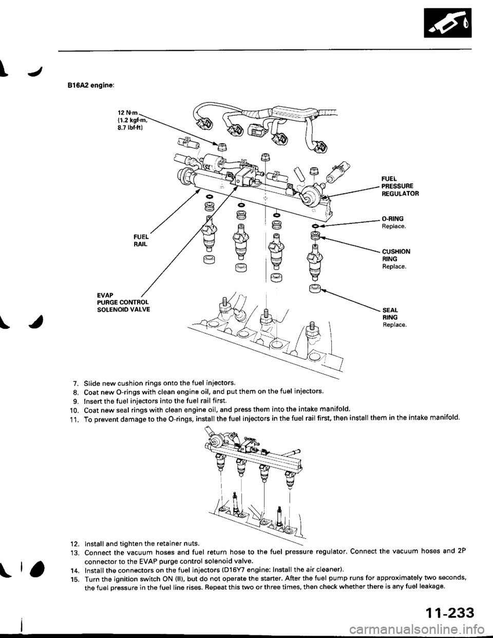
81642 engine:
EVAP
12 N.m
{1.2 kgl m;8.? lbt.ft)
FUELPRESSUREREGULATOR
O.RINGReplace.
cusHloNRINGReplace.
PURGE CONTROLSOLENOID VALVE
\
SEALRINGReplace.
7. Slide new cushion rings onto the fuel injectors.
8. Coat newO-ringswith clean engineoil, and putthem onthefuel injectors.
9. Insert the fuel injectors into the fuel rail first.
10. Coatnewseal rings with clean engine oil,and press them intothe intake manifold.
11. To prevent damage to the O-rings, installthe fuel injectors inthefuel rail first, then install them inthe intake manifold.
'12. Install and tighten the retainer nuts.
13. Connect the vacuum hoses and fuel return hose to the fuel pressure regulator, Connect the vacuum hoses and 2P
connector to the EVAP purge control solenoid valve.
14. Install the connectors on the fuel inl'ectors (D16YI engine; Install the air cleaner).
15. Turn the ignition switch ON (ll), butdo not operate the starter. After the tuel pump runs for approximately two seconds,
the fuel pressure in the fuel line rises. Repeat this two or three times, then check whether there is any fuel leakage.
11-233
Page 512 of 2189
Intake Air System
\JSystem DescriPtion
The system supp|ies air for a|| engine needs' |t consists of the intake air pipe' Air C|eaner (ACL}, intake air duct, Thrott|e
Body (TB), ldle Air control (lAc) valve and intake manifold. A resonator in the intake air pipe provides additional silencing
as air is drawn into the system.
D16Y5, D16Y8, 816A2 engine {M/Tl
YEL/ - From PGM-FIaLK - MA|N RELAY
BLK/BLU
-- ORN
INTAKEAIRDUCT
IROTARYIIAC VALVE
Iaru
ENGINECOOLANT
BLK/
INTAKEAIR DUCT
I
D16Y5 engine (CVT), D16Y8 engine (A/T)' f'ttlxr ,tla"tpoto
D16Y7 engine:
{ROTARY)IAC VALVE
VARIOUSSENSORS
INTAKEAIRPIPE
tr
RESONATOR
!r,
IAC VALVE
BLK
11-243
Page 519 of 2189
Intake Air System
Fuel Injection Air (FlA) Controt System I'99 - 00 Dl6yg enginel
Dsscription
When the engine running lengine coolant below 149oF (6S"C)], the fuel Injection Air (FtA) Control Valve sends intake air tothe fuel iniectors.
E> : INTAKEAIR
FUELINJECTOB
11-250
Page 520 of 2189
\J
Fuol Iniection Air {FlA) Contlol Valve T$ting
1. Start the engine.
2. Remove the vacuum hose from the fitting on the
intake air duct, and connect a vacuum gauge to the
nose.
NOTE: Engine coolant temperature must be below
149"F (65"C).
VACUUM PUMP/GAUGE,
0-30 in.Hg.A973X - 041 -XXXXX
Raise and lower the engine speed, and make sure
the vacuum gauge reading changes as the engine
speed changes.
lf vacuum reading does not change check these
rtems:
. The vacuum lines of FIA system for misrouting,
leakage, breakage and clogging.
. The FIA controt valve for cracks or damage
. The cooling system (see section 10).
Hold the engine at 3,OOO rpm with no load (in Park
or neutral) until the radiator fan comes on, th€n let
it idle and recheck.
lf vacuum reading changes check these items:
a The FIA control valve for cracks or damage.
. The cooling system (see section 10).
11-251
Page 521 of 2189

Emission Gontrol System
System Description
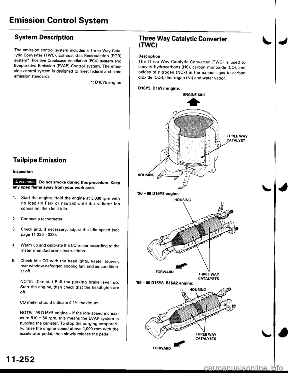
The emission control system includes a Three Way Cata-lytic Convener (TWC), Exhaust Gas Recirculation (EGR)
system,. Positive Crankcase Ventilation (pCV) system andEvaporative Emission (EVAP) Control system. The emis-sion control system is designed to meet federal and stateemission standards.*: D16Y5 engine
Tailpipe Emission
Inspestion
@@ Do not smoke during ihis procedure. Keepany open flame away from your work area.
1. Start the engine. Hold the engine at 3,000 rpm withno load (in Park or neutral) until the radiator fancomes on. then let it idle.
2. Connect a tachometer.
Check and, if necessary, adjust the idle speed (see
page 11-220 - 223).
Warm up and calibrate the CO meter according to themeter manufacturer's instructions.
Check idle CO with the headlights, heater blower,rear window defogger, cooling fan, and air condition-er off.
NOTE: (Canada) Pull the parking brake lever up.Start the engine, then check that the headlights areoff.
CO mete. should indicate 0.1% maximum.
NOTE: '98 Dl6Y5 engine - lf the idle speed incress-es to 8101 50 rpm, this means the EVAp system ispurging the canister. To stop the purging temporari-ly. raise the engine speed above 1,000 rpm with theaccelerator pedal, then slowly release the pedal.
11-252
eFORWARD -
Three Way Catalytic Converter
(TWCI
Doscription
The Three Way Catalytic Converter (TWC) is used toconven hydrocarbons (HC), carbon monoxide (CO), andoxides of nitrogen (NOx) in the exhaust gas to carbondioxide (COr), dinitrogen (N,) and water vapor.
D15Y5, D16
, engine:
'99 - 00 D16Y8, 81642 engine:
ENGINE SIDE
t