1996 HONDA CIVIC air mixture
[x] Cancel search: air mixturePage 373 of 2189

PGM-FI System
System Description
CKP/TDC/CYP Sensor
MAP Sensor
IAT SensorTP SensorEGR Valve Lift Sensor*'Primary H02SSecondary HO2SVSSBARO SensorELD*'KS€Starter SignalALT FR SignalAir Conditioning SignalA/T Gear Position SignalBattery Voltage {lGN.1}Erake Switch SignalPSP Switch SignalFuel Tank Pressure Sensor*iVTEC Pressure Switch*5Clutch Switch Signal*6Countershaft Speed SensornBMainshaft Speed Sensorrs
-\
----t /
F;ilrr j"-----fi-tri-'r.;l
Fb"t."'i" d" c;;il
F,h"'c;;tr*".io";-l
@."r.l"sc;;ll
EaM/PcM B""k-p F"""till
r\
-:/
Fuel IniectorsPGM-Fl Main Belay {Fuel Pump)MILIAC Valve!y'C Compressor Clutch RelayRadiator Fan Relay*,Condenser Fan RelayALT*'lcMEVAP Purge Control Solenoid
Primary HO2S HeaterSecondary H02S HeaterEGR Control Solenoid Valve*rEGR valve*6EVAP Bypass Solenoid Valve*'EVAP Control Canister Vent Shut
VTEC Solenoid Valve*5DLCLock-up Control Solenoid Valve*aShift Control Solenoid Valve*3Linear Solenoid Valve*3
*1: Dl6Y5 engine*2: USA model*3: CW (D16Y5 ensine), D16Y8 engine and 81642 ensine*4: '96 D16Y8 engine lcoupe),'97 Dl6Y7 engine (coupe: KL model, sedan: KL (LX) model),'97 D16Y8 engine {coupe: all models, sedan: KLmodel),'98-all models,'99'all models,'00-all models+5: D16Y5, D16Y8,816A2 engine*6: M/T (D16Y5 enginei*7: CVT 1D'l6Y5 engine)+8: A/T (D16Y7, D16Y8 engine)*9: '96 D16Y5 engine,'96 D16Y7 engine,'96 Dl6Y8 engine (sedan),'97 D16Y5 engine,'97 Dl6Y7 engine (coupe: KA, KC models, sedan:KA, KC, KL (LX) models, hatchback: all models),'97 D16Y8 engine (sedan: KA, KC modelsi
PGM-FI Sy3lem
The PGM-Fl system on this model is a sequential multipon fuel injection system.
Fuel iniector Timing and Duration
The ECM/PCM contains memories for the basic discharge durations at various engine speeds and manifold air flow rates.
The basic discharge duration, after being read out from the memory. is further modified by signals sent from various sen-
sors to obtain the final discharge duration.
ldle Air Control
ldle Air Control Valve llAC Valve)
When the engine is cold. the A,/C compressor is on, the transmission is in gear, the brake pedal is depressed, the P/S load
is high, or the alternator is charging, the ECM/PCM controls current to the IAC Valve to maintain the correct idle speed.
lgnition Timing Control
. The ECM/PCM contains memories for basic ignition timing at various engine speeds and manifold air flow rates.
lgnition timing is also adjusted for engine coolant temperature.
. Aknockcontrol system was adopted which sets the ideal ignition timing for the octane rating ofthegasoline used.*3
Othgr Control Funqtions
1. Starting Control
When the engine is started, the ECM/PCM provides a rich mixture by increasing fuel injector duration.
2. Fuel Pump Control
. When the ignition switch is initially turned on, the ECM/PCM supplies ground to the PGM-Fl main relay that sup-plies current to the fuel pump for two seconds to pressurize the fuel system.. When the engine is running, the ECI\4PCM supplies ground to the PGM-FI majn relay that supplies current to the fuel
oumo.
. When the engine is not running and the ignition is on, the ECM/PCM cuts ground to the PGM-FI main relay which
cuts current to the fuel pump.
11-104
INPUTS
ENGINE CONTROL MODULE (ECMY
POWERTRAIN CONTROL MODULE (PCM) OUTPUTS
Page 374 of 2189

3.
5.
6.
1.
Fuel Cut-off Control
. During deceleration with the throttle valve closed, current to the fuel injectors is cut off to improve fuel economy at
speeds over the following rpm:. D16Y5 engine (M/T):850 rpm. D]6Y5 engine (CVT), D'16Y8 engine (USA M/T): 920 rpm
. Dl6Y8 engine (USA A,/I), D16Y7 engine (USA A,/T);910 rpm
. D16Y8 engine (Canada M/T), D16Y7 engine (canada): 990 rpm
' D16Y8 engine (Canada M/T): 1,000 rpm
. 816A2 engine: 970 rpm
. Fuel cut-off action also takes place when engine speed exceeds 6,900 rpm (D16Y5, D16Y7 engine; D'16Y8 engine:
7,000 rpm. 816A2 engine: 8.100 rpm), regardless of the position of the throttle valve, to protect the engine from
over-rewing. With '99 Dl6Y7 engine (A,/T) and '99 D16Y8 engine (A./T), the PCM cuts the fuel at engine speeds over
5,000 rpm when the vehicle is not moving.
IVC Compressor Clutch Relay
When the ECM/PCM receives a demand for cooling from the air conditioning system, it delays the compressor from
being energized, and enriches the mixture to assure smooth transition to the A,/C mode
Evaporative Emission (EVAP) Purge Control Solenoid Valve*'
When the engine coolant temperature is above 154'F (68'C). the ECM/PCM controls the EVAP purge control solenoid
valve which controls vacuum to the EVAP purge control canister.
Evaporative Emission (EVAP) Purge Control Solenoid Valve*a
When the engine coolant temperature above 154"F (68"C), intake air temperature above 32"F (0'C) and vehicle speed
above 0 mile (0 km/h) or [Ay'C compressor clutch on and intake air temperature above 160"F (41'C)], the ECM/PCM
controls the EVAP purge control solenoid valve which controls vacuum to the EVAP purge control canister.
Exhaust Gas Recirculation (EGR) Control Solenoid Valve*?
When EGR is required for control of oxides of nitrogen (NOx) emissions. the ECM controls the EGR control solenoid
valve which supplies regulated vacuum to the EGR valve
Alternator Control
The system controls the voltage generated at the alternator in accordance with the electrical load and driving mode,
which reduces the engine load to improve the fuel economy.
ECM/PCM Fail-safe/Back-up Functions
1. Fail safe Function
When an abnormality occurs in a signal from a sensor, the ECM/PCM ignores that signal and assumes a pre-pro-
grammed value for that sensor that allows the engine to continue to run.
2. Back-uD Function
When an abnormality occurs in the ECM/PCM itself, the fuel injectors are controlled by a back-up circuit independent
of the system in order to permit minimal driving.
3. Self diagnosis Function lMalfunction Indicator Lamp (MlL)l
When an abnormality occurs in a signal from a sensor, the ECM/PCM supplies ground for the lvllL and stores the DTC
in erasable memory. When the ignition is initially turned on, the ECM/PCM supplies ground for the MIL for two sec-
onds to check the MIL bulb condition.
4. Two Trip Detection Method
To prevent false indications, the Two Trip Detection Method is used for the HO2S, fuel metering-related. idle control
system, ECT sensor, EGR system and EVAP control system self-diagnostic functions. When an abnormality occurs,
the ECM/PCM stores it in its memory. When the same abnormality recurs after the ignition switch is turned OFF and
ON 0l) again, the ECM/PCM informs the driver by lighting the MlL. However, to ease troubleshooting, this function is
cancelled when you jump the service check connector. The MIL will then blink immediately when an abnormality
occurs,
5. Two (or Three) Driving Cycle Detection Method
A "Driving Cycle" consists ot starting the engine. beginning closed loop operation, and stopping the engine. lf misfir-
ing that increases emissions is detected during two consecutive driving cycles, or TWC deterioration is detected dur-
ing three consecutive driving cycles, the ECM/PCM turns the MIL on. However, to ease troubleshooting, this function
is cancelled when you jump the service check connector. The MIL will then blink immediately when an abnormality
occurs.
(cont'd)
1 1-1 05
.1.
Page 1395 of 2189
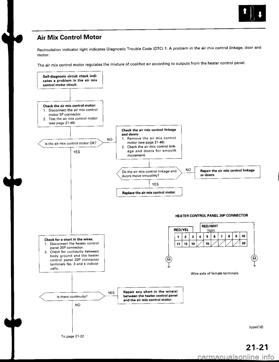
Air Mix Gontrol Motor
Recirculation indicator light indicates Diagnostic Trouble code (DTC) 1l A problem in the air mix control linkage, door and
motor.
The air mix control motor regulates the mixture of cool/hot air according to outputs from the heater control panel'
Self-diagnosis circuit check indi'
cates a Problem in the air mix
conlrol motor circuit,
Check th6 aii mix conirol motor:
1. Disconnect the air mix control
motor 5P connector.
2. Test the air mix control motor(see page 21-46).
check the air mix control linkage
and doors:1. Remove the air mix control
motor (see Page 21-46)
2. Check the air mix control link-
age and doors lor smooth
movement.
ls the air mix control motor OK?
Do the air mix control linkage and
doors move smoolhlY?
R€olace the air mix control motor'
Check tor a short in the wiles:
1. Disconnect the heater controlpanel 20P connector-2. Check for continuitY between
body ground and the heater
control panel 20P connector
terminals No.3 and 4 individ'
uaIY.
Ropair any short in th€ wire{s}
betweon the heater control Paneland the air mix control motor'
HEATER CONTROL PANEL 2OP CONNECTOR
RED/WHTRED/YEL
Wire side ot female terminals
(cont'd)
fo page 21-22
21-21
Page 1446 of 2189
A/C Service Tips and Precautions
The air conditioner system uses HFC-134a (R-134a) refrigerant and polyalkyleneglycol (PAG) refrigerant oil*, which are not
compatible with CFC-12 (R-12) refrigerant and mineral oil. Do not use R-12 refrigerant or mineral oil in this system, and do
not attempt to use R-12 servicing equipmenU damage to the air conditioner system or your servicing equipment will result.*Sanden SP-10:
. P/N 38897 - P13 - A0lAH: 120 ml 14ll.oz, 4.2lmp.oz)
. P/N 38899 - P13 - A0l | 40 mf 11 1/3ll.oz,1.4 lmp'oz)
Use only service equipment that is U.L. listed and is certified to meet the requirements of SAE J2210 to remove R 134a
from the air conditioner system.
CAUTION: Exposure to air conditioner ref;ige;ant and lubricant vapol or mist can irritate syes, nose and throat, Avoid
breathing the air conditioner refrigerant and lubricant vapor or misl.
lf accidental system discharge occurs, ventilate work area before resuming service.
R-'134a service equipment or vehicle air conditioner systems should not be pressure tested or leak tested with compressed
ai.
!@@ some mixtures of air and R-t3ila have been shown to be combustible at elevated pressures and can result
in tire or explosion causing iniury or property damage. Never use compressed air lo pressure tesl R-134a service equip-
ment or vehicle 8ir conditioner systoms.
Additional health and safety information may be obtained from the refrigerant and Iubricant manufacturers.
L Always disconnect the negative cable from the battery whenever replacing air conditioning pans.
2. Keep moisture and dust out of the system. When disconnecting any lines, plug or cap the fittings immediately; don't
remove the caps or plugs until just before you reconnect each line.
3. Before connecting any hose or line, apply a few drops of refrigerant oilto the O-ring.
4, When tightening o. loosening a fitting, use a second wrench to support the matching fitting.
5. When discharging the system, use a R-134a refrigerant recovery/recycling/charging station; don't release refrigerant
into the atmosphere,
6. Add refrigerant oil after replacing the following parts:
NOTE:
. To avoid contamination, do not return the oil to the container once dispensed, and never mix it with other refriger-
ant oils.
. lmmediately after using the oil, replace the cap on the container, and seal it to avoid moisture absorption.
. Do not spill the refrigerant oil on the vehicle; it may damage the paint; if the refrigerant oil contacts the paint, wash
it off immediately.
Condenser .......2o ml (2/3 fl.oz, 0.7 lmp.ozl
Evaporator .,.,.,. i[5 m{ 11 213 tl.oz,1,6lmp.ozl
Line or hose ..... 10 mf (1/3 fl.oz, 0.4 lmp.ozl
Receiver/Dryer 10 m{ (1/3 fl.oz,0.'l lmp.ozl
Leakage repair 25 m{ (5/6 fl.oz, 0.9 lmp.ozl
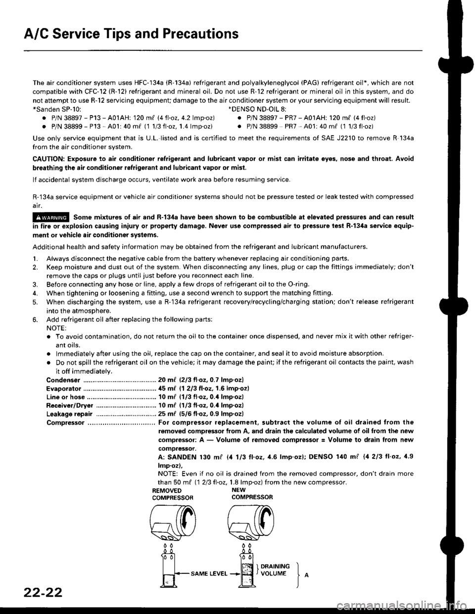
Comptessor ... For compressor replacement. subtract the volume of oil drained trom the
removed compressor from A, and drain the calculated volume of oilfrom the new
compressor: A - Volume of removed compressor: Volume to drain from new
comoressor.
A: SANDEN 130 mf l/t 113 ll.oz, 4.6 lmp'ozl; DENSO 140 mf {4 213 ll'oz, 1.9
lmp.oz),
NOTE: Even if no oil is drained from the removed compressor, don't drain more
than S0 m{ 112Ell.oz,1.8 lmp.oz) fromthe new compressor.
REMOVED NEW
COMPRESSORCOMPRESSOR
*DENSO ND-OlL 8l
. P/N 38897 - PR7 - A01AH: 120 ml (4 fl.oz)
. P/N 38899 PR7-A01:40mf (1 1/3fl'oz)
rereW W0000
22-22
-0_!- -0_a
Tol l00l
| | lffi 1 onrrrutrc I
fi+-sAME
LEvEr...+jEf,voLUME
J
^
Page 1451 of 2189
Recovery
Use only service equipment that is U.L.-listed and is cer-
tified to meet the requirements of SAE J2210 to remove
HFC-134a (R-134a) from the air conditioner system
CAUTION: Exposure to air conditioner relrigerant and
lubricant vapor or mist can illitate eyes, noss and
throat. Avoid breathing the ail conditioner refrigerant
and lubricant vapor or mist.
lf accidental system discharge occurs, ventilate work
area before resuming service.
R-134a service equipment or vehicle air conditioner sys-
tems should not be pressure tested or leak tested with
compressed air.
!@@ some mixtures ot air and R'13'[a havo been
strown to be combustiblg at elevated pressures and Gan
resuh in fire or explosion causing iniury or property dam-
age, Never use compressed air to pressure test R-134a
service equipment or vehicle air conditioner systems.
Additional health and safetv information may be obtained
from the refrigerant and lubricant manufacturers.
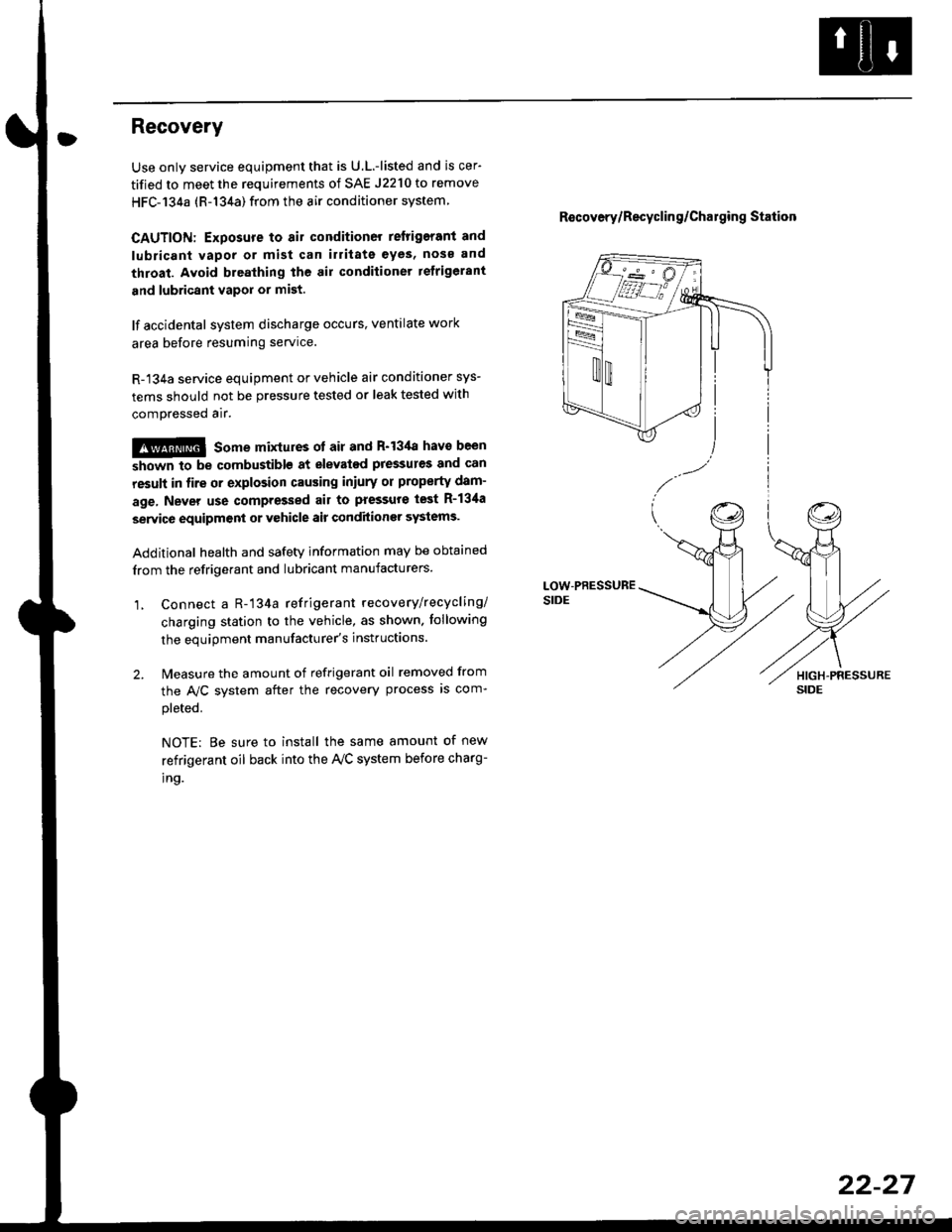
1, Connect a R-'134a refrigerant recove rylrecycling/
charging station to the vehicle, as shown. tollowing
the equipment manufacturer's instluctions.
2. Measure the amount of refrigerant oil removed from
the A/C svstem after the recovery process is com-
pleted.
NOTE: Be sure to install the same amount of new
refrigerant oil back into the Iy'C system before charg-
tno.
R€covery/Recyclin g/Cha19ing Station
22-27
Page 1469 of 2189
A/C System Service
Evacuation
Use only service equipment that is U L.-listed and is cer-
tified to meet the requirements oJ SAE J2210 to remove
HFC-134a (R-134a) from the air conditioner system'
CAUTION: Exposure to air conditioner reftig€lant and
lubricant vapor or misi can irrhaie eyes. noso and throat'
Avoid breathing the ail condhioner lefrigelant and lubri
cant vapor or mist.
lf accidental system discharge occurs, ventilate work
area before resuming servace.
R-134a service equipment or vehicle air conditioner sys-
tems should not be pressure tested or leak tested with
comDressed air.
!!@@ some mixtures of air and R-13'[8 haYo boon
ffiiE-n to be "ombustible at elovatod pressurcs and can
result in fire or explosion causing iniury or propsrtY
damag€. Never uso complsssod air to pre3surs tost R-
1344 ssrvico equipment or vehicle air conditioner sy3-
tems,
Additional health and safety information may be obtained
from the refrigerant and lubricant manuJacturers'
When an A,/C System has been opened to the atmo-
sphere, such as during installation or repair, it must
be evacuated using a R-134a refrigerant recovery/
recycling/charging station. (lf the system has been
open for several days, the receiver/dryer should be
replaced, and the system should be evacuated for
several hours.)
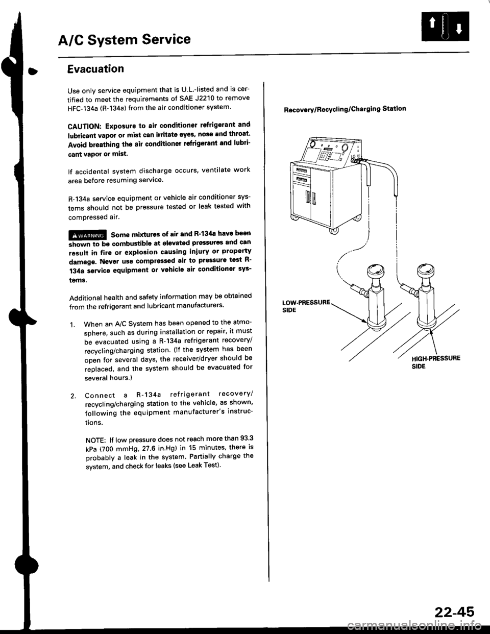
Connect a R-134a refrigerant recovery/
recycling/charging station to the vehicle, as shown'
following the equipment manufacturer's instruc-
trons.
NOTE: lf low pressure does not reach more than 93 3
kPa (7OO mmHg,27.6 in.Hgl in 15 minutes, there is
probably a leak in the system Partially charge the
system, and check for leaks (see Leak Test)
1.
R6covory/Recyclin g/Chal9ing Station
22-45'
Page 1470 of 2189
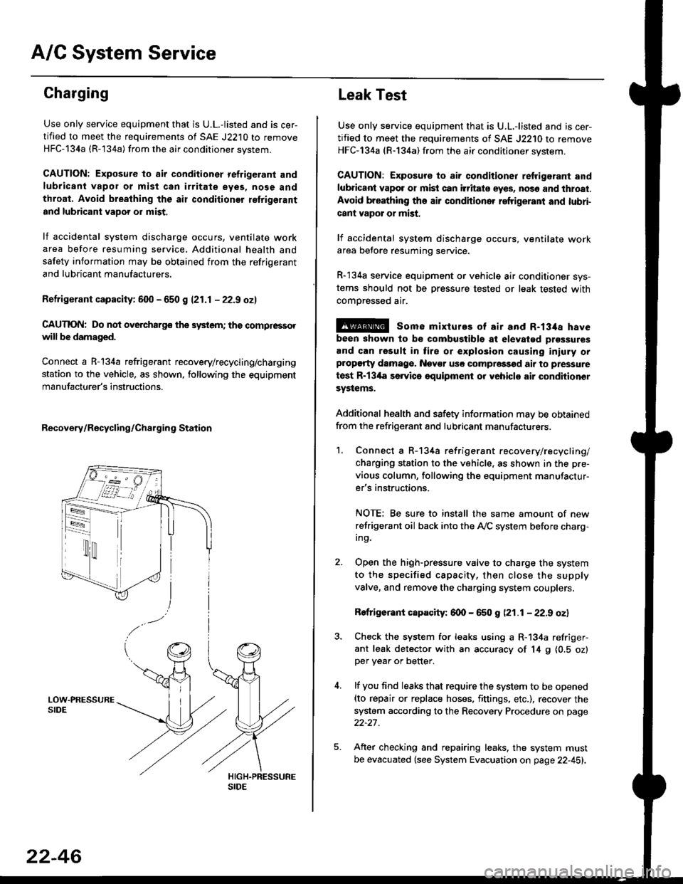
A/C System Service
Charging
Use only service equipment that is U.L.-listed and is cer-
tified to meet the requirements of SAE J2210 to remove
HFC-134a (R-134a) from the air conditioner system.
CAUTION: Exposure to air conditioner refrigerant and
lubricant vapor or mist can irritale eyes, nose and
throat. Avoid breathing the air conditioner retrigerant
and lubricant vaoor or mist,
lf accidental system discharge occurs, ventilate workarea before resuming service, Additional health and
safety information may be obtained from the refrigerant
and lubricant manufacturers.
Refrigerant capacityt 600 - 650 g 121.1 - 22.9 ozl
CAUnON: Do not overcharg€ the system; the comprcssor
will be damaged.
Connect a R-134a refrigerant recovery/recycling/charging
station to the vehicle, as shown, following the equipment
manufacturer's instructions.
Recovery/Recycling/Charging Station
22-46
Leak Test
Use only service equipment that is U.L,-listed and is cer-
tified to meet the requirements of SAE J2210 to remove
HFC-134a (R-134a) from the air conditioner system.
CAUTION: Exposure io air conditioner refrigerant and
lubricant vapot or mist can itritats eyes, no36 and thtoat.
Avoid breathing the air conditioner refrigeranl and lubri-
cant vapor or mist,
lf accidental system discharge occurs, ventilate workarea betore resuming service.
R-134a service equipment or vehicle air conditioner sys-
tems should not be pressure tested or leak tested with
comoressed air.
@ some mixtures of air and R-134a have
been shown to be combugtibls at elevatgd prossures
and can result in tire or explosion causing iniuly orplopgrty damage. Nev€r usc compre33od air to pressure
test R-13'la servica oquipment or yohiclo air conditionor
systems.
Additional health and safety information may be obtained
from the refrigerant and lubricant manufacturers.
1. Connect a R-134a refrigerant recove rylrecycling/
charging station to the vehicle, as shown in the pre-
vious column, following the equipment manufactur-
er's instructions.
NOTE; Be sure to install the same amount of new
refrigerant oil back into the A,/C system before charg-In9.
Open the high-pressure valve to charge the system
to the specified capacity, then close the supply
valve, and remove the charging system couplers.
Rofrigerant capacity: 600 - 650 g (21.1 - 22.9 oz)
Check the system for leaks using a R-134a refriger-
ant leak detector with an accuracy of 14 9 10.5 ozlper yea. or better.
lf you find leaks that require the system to be opened(to repair or replace hoses. fittings. etc.), recover the
system according to the Recovery Procedure on page
22-27.
After checking and repairing leaks. the system must
be evacuated (see System Evacuation on page 22-451.
Page 1952 of 2189
![HONDA CIVIC 1996 6.G Workshop Manual Air Delivery
- 99-00 Models
a
r--T----.I UNDER-HOOD UNDEB-DASH
| ,ry:i.l? IFUSE/RELAY I t::u:E^tt l:usE/RELAyi
- -{-;;; -
I PJ,.,8.J390 i
-
T;; ;
- - - - -
I H$3,,8
i 1;:t"* ];FPJ", i i m. HONDA CIVIC 1996 6.G Workshop Manual Air Delivery
- 99-00 Models
a
r--T----.I UNDER-HOOD UNDEB-DASH
| ,ry:i.l? IFUSE/RELAY I t::u:E^tt l:usE/RELAyi
- -{-;;; -
I PJ,.,8.J390 i
-
T;; ;
- - - - -
I H$3,,8
i 1;:t"* ];FPJ", i i m.](/manual-img/13/6068/w960_6068-1951.png)
Air Delivery
- '99-'00 Models
a
r--T----.I UNDER-HOOD UNDEB-DASH
| ,ry:i.l? IFUSE/RELAY I t::u:E^tt l:usE/RELAyi
- -{-;;; -
I PJ,'.',8.J390 i
-
T;; ;
- - - - -
I H$3,',8
i 1;:t"* ];FPJ", i i m'.u" se€power i "t8L,,
i t i a l'"0 r3l",lli"i:" aL--{..-----J L-J..----5::---:-J
"",":"rfi?ll, '[r;T:1"
-",*"1-J
*-*..l
,n", ".u I lt I
lr !I See Power I See Power Distnbution.I Distribution, U page 1o-9.
,, L::':l------- *Y=l
"*o "."",,t
[
*,:.'.Y%
Irel-
lt
:'l-4riffi
MODECONTROLMOTOR
;L:L{;I{,tt't{ {f
SensorGround grgund
venl
Air mix5Y poientia,reTgrano9 rnrrul
gIouno
RecircSwilcfi switchcommon mput
Recirc S$,itchtED LEDcontrol common
RECIRCULATIONCONTROLMOTORPHOTO 139
CONTROLPANEL
vtEw 76
So€ Roar II Windolv :
a
Htr Ttr =tr ;l *tr :tr *,tr THtr Ttr =tr ;l *tr :tr *tr Ttr
'il
Ti
Battery lgnition Mod€ Mode Mode L4ode Mode l od€(back up) input detrost h€av heat heav vent motorR€circulato Fresh
IJ
Delogger
L------- ---J
HEATERPUSHswtTcHEs
delrost
Air Airmix mixcool hot;;-; J'J - - - J-JL i- 5:- - -
SLK
812
AFN
13
BFN
See GroundDistribution,page 14-5.
c4 t, cl
WHT I ONN
ft++il
c723
F ash/RoclreSwftch
Reclrc.oat LEo
IY
tt
L__l--tGo3,
See RearWindowOetogger
AIR MIXTURECONTROLMOTOR
(
c9 Y cl1
61-2