1996 CHRYSLER VOYAGER fuel pressure
[x] Cancel search: fuel pressurePage 1233 of 1938
(3) Install cylinder head cover, torque nuts to 14.7
N´m (132 in. lbs.).
(4) Install coolant pressure tank.
(5) Install breather hose.
(6) Install generator bracket, tighten bolts to 7
N´m (4 ft. lbs.).
(7) Connect the service valves to the A/C compres-
sor ports, if equipped with air conditioning.
(8) Connect battery cable.
VALVE SPRINGSÐCYLINDER HEAD NOT
REMOVED
This procedure can be done with the engine cylin-
der head installed on the block.
REMOVAL
Each valve spring is held in place by a retainer
and a set of conical valve locks. The locks can be
removed only by compressing the valve spring.
(1) Remove the engine cylinder head cover, refer to
cylinder head cover removal in this section.
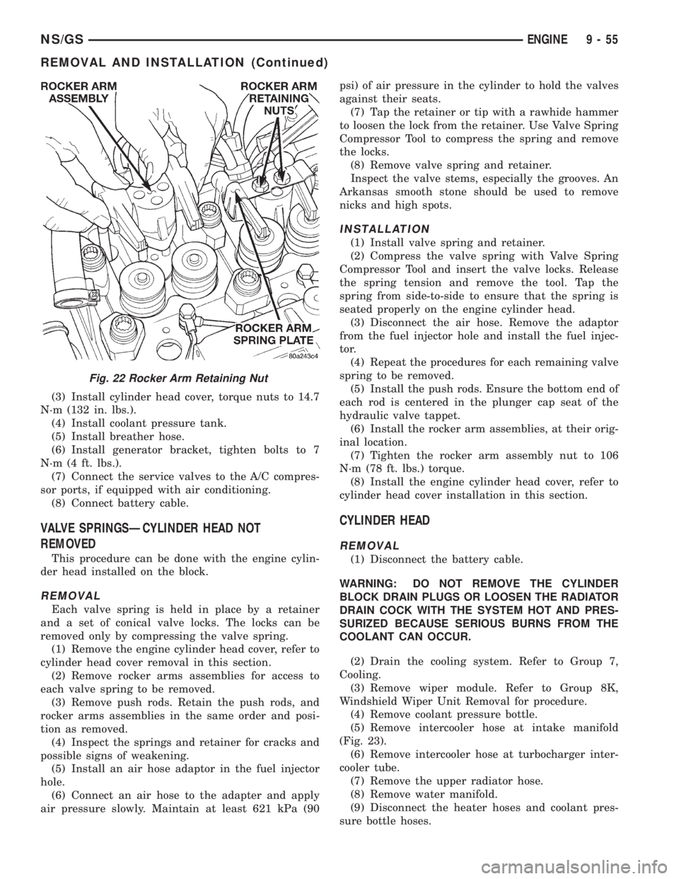
(2) Remove rocker arms assemblies for access to
each valve spring to be removed.
(3) Remove push rods. Retain the push rods, and
rocker arms assemblies in the same order and posi-
tion as removed.
(4) Inspect the springs and retainer for cracks and
possible signs of weakening.
(5) Install an air hose adaptor in the fuel injector
hole.
(6) Connect an air hose to the adapter and apply
air pressure slowly. Maintain at least 621 kPa (90psi) of air pressure in the cylinder to hold the valves
against their seats.
(7) Tap the retainer or tip with a rawhide hammer
to loosen the lock from the retainer. Use Valve Spring
Compressor Tool to compress the spring and remove
the locks.
(8) Remove valve spring and retainer.
Inspect the valve stems, especially the grooves. An
Arkansas smooth stone should be used to remove
nicks and high spots.
INSTALLATION
(1) Install valve spring and retainer.
(2) Compress the valve spring with Valve Spring
Compressor Tool and insert the valve locks. Release
the spring tension and remove the tool. Tap the
spring from side-to-side to ensure that the spring is
seated properly on the engine cylinder head.
(3) Disconnect the air hose. Remove the adaptor
from the fuel injector hole and install the fuel injec-
tor.
(4) Repeat the procedures for each remaining valve
spring to be removed.
(5) Install the push rods. Ensure the bottom end of
each rod is centered in the plunger cap seat of the
hydraulic valve tappet.
(6) Install the rocker arm assemblies, at their orig-
inal location.
(7) Tighten the rocker arm assembly nut to 106
N´m (78 ft. lbs.) torque.
(8) Install the engine cylinder head cover, refer to
cylinder head cover installation in this section.
CYLINDER HEAD
REMOVAL
(1) Disconnect the battery cable.
WARNING: DO NOT REMOVE THE CYLINDER
BLOCK DRAIN PLUGS OR LOOSEN THE RADIATOR
DRAIN COCK WITH THE SYSTEM HOT AND PRES-
SURIZED BECAUSE SERIOUS BURNS FROM THE
COOLANT CAN OCCUR.
(2) Drain the cooling system. Refer to Group 7,
Cooling.
(3) Remove wiper module. Refer to Group 8K,
Windshield Wiper Unit Removal for procedure.
(4) Remove coolant pressure bottle.
(5) Remove intercooler hose at intake manifold
(Fig. 23).
(6) Remove intercooler hose at turbocharger inter-
cooler tube.
(7) Remove the upper radiator hose.
(8) Remove water manifold.
(9) Disconnect the heater hoses and coolant pres-
sure bottle hoses.
Fig. 22 Rocker Arm Retaining Nut
NS/GSENGINE 9 - 55
REMOVAL AND INSTALLATION (Continued)
Page 1237 of 1938
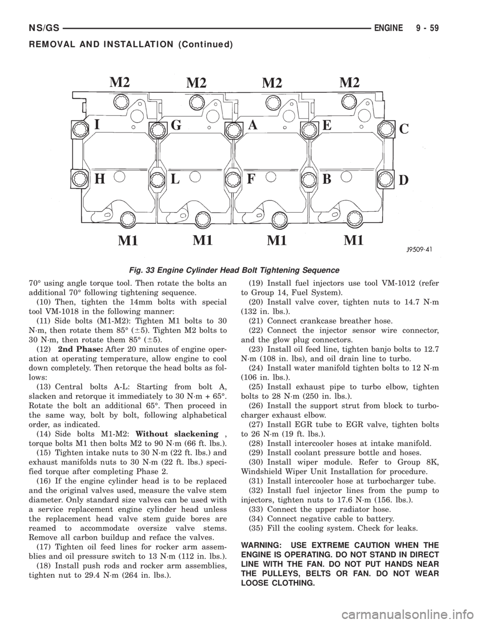
70É using angle torque tool. Then rotate the bolts an
additional 70É following tightening sequence.
(10) Then, tighten the 14mm bolts with special
tool VM-1018 in the following manner:
(11) Side bolts (M1-M2): Tighten M1 bolts to 30
N´m, then rotate them 85É (65). Tighten M2 bolts to
30 N´m, then rotate them 85É (65).
(12)2nd Phase:After 20 minutes of engine oper-
ation at operating temperature, allow engine to cool
down completely. Then retorque the head bolts as fol-
lows:
(13) Central bolts A-L: Starting from bolt A,
slacken and retorque it immediately to 30 N´m + 65É.
Rotate the bolt an additional 65É. Then proceed in
the same way, bolt by bolt, following alphabetical
order, as indicated.
(14) Side bolts M1-M2:Without slackening,
torque bolts M1 then bolts M2 to 90 N´m (66 ft. lbs.).
(15) Tighten intake nuts to 30 N´m (22 ft. lbs.) and
exhaust manifolds nuts to 30 N´m (22 ft. lbs.) speci-
fied torque after completing Phase 2.
(16) If the engine cylinder head is to be replaced
and the original valves used, measure the valve stem
diameter. Only standard size valves can be used with
a service replacement engine cylinder head unless
the replacement head valve stem guide bores are
reamed to accommodate oversize valve stems.
Remove all carbon buildup and reface the valves.
(17) Tighten oil feed lines for rocker arm assem-
blies and oil pressure switch to 13 N´m (112 in. lbs.).
(18) Install push rods and rocker arm assemblies,
tighten nut to 29.4 N´m (264 in. lbs.).(19) Install fuel injectors use tool VM-1012 (refer
to Group 14, Fuel System).
(20) Install valve cover, tighten nuts to 14.7 N´m
(132 in. lbs.).
(21) Connect crankcase breather hose.
(22) Connect the injector sensor wire connector,
and the glow plug connectors.
(23) Install oil feed line, tighten banjo bolts to 12.7
N´m (108 in. lbs), and oil drain line to turbo.
(24) Install water manifold tighten bolts to 12 N´m
(106 in. lbs.).
(25) Install exhaust pipe to turbo elbow, tighten
bolts to 28 N´m (250 in. lbs.).
(26) Install the support strut from block to turbo-
charger exhaust elbow.
(27) Install EGR tube to EGR valve, tighten bolts
to 26 N´m (19 ft. lbs.).
(28) Install intercooler hoses at intake manifold.
(29) Install coolant pressure bottle and hoses.
(30) Install wiper module. Refer to Group 8K,
Windshield Wiper Unit Installation for procedure.
(31) Install intercooler hose at turbocharger tube.
(32) Install fuel injector lines from the pump to
injectors, tighten nuts to 17.6 N´m (156. lbs.).
(33) Connect the upper radiator hose.
(34) Connect negative cable to battery.
(35) Fill the cooling system. Check for leaks.
WARNING: USE EXTREME CAUTION WHEN THE
ENGINE IS OPERATING. DO NOT STAND IN DIRECT
LINE WITH THE FAN. DO NOT PUT HANDS NEAR
THE PULLEYS, BELTS OR FAN. DO NOT WEAR
LOOSE CLOTHING.
Fig. 33 Engine Cylinder Head Bolt Tightening Sequence
NS/GSENGINE 9 - 59
REMOVAL AND INSTALLATION (Continued)
Page 1258 of 1938
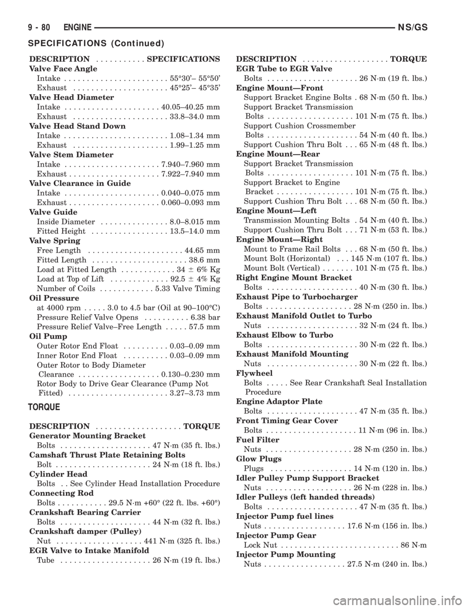
DESCRIPTION...........SPECIFICATIONS
Valve Face Angle
Intake.......................55É30'± 55É50'
Exhaust.....................45É25'± 45É35'
Valve Head Diameter
Intake.....................40.05±40.25 mm
Exhaust.....................33.8±34.0 mm
Valve Head Stand Down
Intake.......................1.08±1.34 mm
Exhaust.....................1.99±1.25 mm
Valve Stem Diameter
Intake.....................7.940±7.960 mm
Exhaust....................7.922±7.940 mm
Valve Clearance in Guide
Intake.....................0.040±0.075 mm
Exhaust....................0.060±0.093 mm
Valve Guide
Inside Diameter...............8.0±8.015 mm
Fitted Height.................13.5±14.0 mm
Valve Spring
Free Length.....................44.65 mm
Fitted Length.....................38.6 mm
Load at Fitted Length............3466% Kg
Load at Top of Lift.............92.564% Kg
Number of Coils............5.33 Valve Timing
Oil Pressure
at 4000 rpm.....3.0to4.5bar(Oil at 90±100ÉC)
Pressure Relief Valve Opens..........6.38 bar
Pressure Relief Valve±Free Length.....57.5 mm
Oil Pump
Outer Rotor End Float..........0.03±0.09 mm
Inner Rotor End Float..........0.03±0.09 mm
Outer Rotor to Body Diameter
Clearance..................0.130±0.230 mm
Rotor Body to Drive Gear Clearance (Pump Not
Fitted)......................3.27±3.73 mm
TORQUE
DESCRIPTION...................TORQUE
Generator Mounting Bracket
Bolts....................47N´m(35ft.lbs.)
Camshaft Thrust Plate Retaining Bolts
Bolt.....................24N´m(18ft.lbs.)
Cylinder Head
Bolts . . See Cylinder Head Installation Procedure
Connecting Rod
Bolts...........29.5 N´m +60É (22 ft. lbs. +60É)
Crankshaft Bearing Carrier
Bolts....................44N´m(32ft.lbs.)
Crankshaft damper (Pulley)
Nut ...................441N´m(325 ft. lbs.)
EGR Valve to Intake Manifold
Tube ....................26N´m(19ft.lbs.)DESCRIPTION...................TORQUE
EGR Tube to EGR Valve
Bolts....................26N´m(19ft.lbs.)
Engine MountÐFront
Support Bracket Engine Bolts . 68 N´m (50 ft. lbs.)
Support Bracket Transmission
Bolts...................101N´m(75ft.lbs.)
Support Cushion Crossmember
Bolts....................54N´m(40ft.lbs.)
Support Cushion Thru Bolt . . . 65 N´m (48 ft. lbs.)
Engine MountÐRear
Support Bracket Transmission
Bolts...................101N´m(75ft.lbs.)
Support Bracket to Engine
Bracket.................101N´m(75ft.lbs.)
Support Cushion Thru Bolt . . . 68 N´m (50 ft. lbs.)
Engine MountÐLeft
Transmission Mounting Bolts . 54 N´m (40 ft. lbs.)
Support Cushion Thru Bolt . . . 71 N´m (53 ft. lbs.)
Engine MountÐRight
Mount to Frame Rail Bolts . . . 68 N´m (50 ft. lbs.)
Mount Bolt (Horizontal) . . . 145 N´m (107 ft. lbs.)
Mount Bolt (Vertical).......101N´m(75ft.lbs.)
Right Engine Mount Bracket
Bolts....................40N´m(30ft.lbs.)
Exhaust Pipe to Turbocharger
Bolts...................28N´m(250 in. lbs.)
Exhaust Manifold Outlet to Turbo
Nuts....................32N´m(24ft.lbs.)
Exhaust Elbow to Turbo
Bolts....................30N´m(22ft.lbs.)
Exhaust Manifold Mounting
Nuts....................30N´m(22ft.lbs.)
Flywheel
Bolts.....SeeRear Crankshaft Seal Installation
Procedure
Engine Adaptor Plate
Bolts....................47N´m(35ft.lbs.)
Front Timing Gear Cover
Bolts....................11N´m(96in.lbs.)
Fuel Filter
Nuts...................28N´m(250 in. lbs.)
Glow Plugs
Plugs..................14N´m(120 in. lbs.)
Idler Pulley Pump Support Bracket
Nuts...................26N´m(228 in. lbs.)
Idler Pulleys (left handed threads)
Bolts....................47N´m(35ft.lbs.)
Injector Pump fuel lines
Nuts..................17.6 N´m (156 in. lbs.)
Injector Pump Gear
Lock Nut..........................86N´m
Injector Pump Mounting
Nuts..................27.5 N´m (240 in. lbs.)
9 - 80 ENGINENS/GS
SPECIFICATIONS (Continued)
Page 1268 of 1938
INSTALLATION
(1) Install new upper intake manifold gasket.
NOTE: Center outboard fastener is a double stud.
(2) Tighten upper intake manifold fasteners start-
ing at center and progressing outward in both direc-
tions. Tighten bolts to 28 N´m (250 in. lbs.). Repeat
this procedures until all fasteners are at specified
torque.
(3) Install dipstick tube. Seal tube to cylinder
block using MopartStud N' Bearing Mount Adhe-
sive. Tighten dipstick tube fastener to 12 N´m (105
in. lbs.)
(4) Install dipstick.
(5) Install upper bolt in intake manifold to front
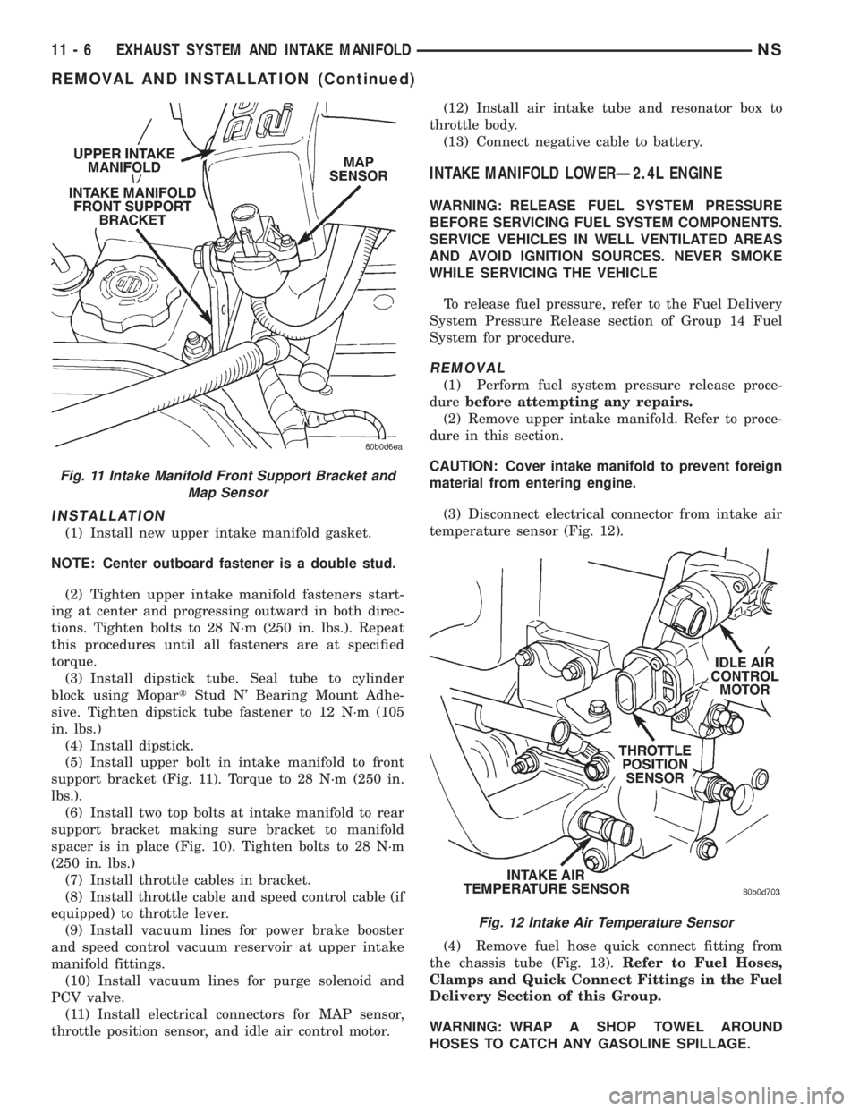
support bracket (Fig. 11). Torque to 28 N´m (250 in.
lbs.).
(6) Install two top bolts at intake manifold to rear
support bracket making sure bracket to manifold
spacer is in place (Fig. 10). Tighten bolts to 28 N´m
(250 in. lbs.)
(7) Install throttle cables in bracket.
(8) Install throttle cable and speed control cable (if
equipped) to throttle lever.
(9) Install vacuum lines for power brake booster
and speed control vacuum reservoir at upper intake
manifold fittings.
(10) Install vacuum lines for purge solenoid and
PCV valve.
(11) Install electrical connectors for MAP sensor,
throttle position sensor, and idle air control motor.(12) Install air intake tube and resonator box to
throttle body.
(13) Connect negative cable to battery.
INTAKE MANIFOLD LOWERÐ2.4L ENGINE
WARNING: RELEASE FUEL SYSTEM PRESSURE
BEFORE SERVICING FUEL SYSTEM COMPONENTS.
SERVICE VEHICLES IN WELL VENTILATED AREAS
AND AVOID IGNITION SOURCES. NEVER SMOKE
WHILE SERVICING THE VEHICLE
To release fuel pressure, refer to the Fuel Delivery
System Pressure Release section of Group 14 Fuel
System for procedure.
REMOVAL
(1) Perform fuel system pressure release proce-
durebefore attempting any repairs.
(2) Remove upper intake manifold. Refer to proce-
dure in this section.
CAUTION: Cover intake manifold to prevent foreign
material from entering engine.
(3) Disconnect electrical connector from intake air
temperature sensor (Fig. 12).
(4) Remove fuel hose quick connect fitting from
the chassis tube (Fig. 13).Refer to Fuel Hoses,
Clamps and Quick Connect Fittings in the Fuel
Delivery Section of this Group.
WARNING: WRAP A SHOP TOWEL AROUND
HOSES TO CATCH ANY GASOLINE SPILLAGE.
Fig. 11 Intake Manifold Front Support Bracket and
Map Sensor
Fig. 12 Intake Air Temperature Sensor
11 - 6 EXHAUST SYSTEM AND INTAKE MANIFOLDNS
REMOVAL AND INSTALLATION (Continued)
Page 1270 of 1938
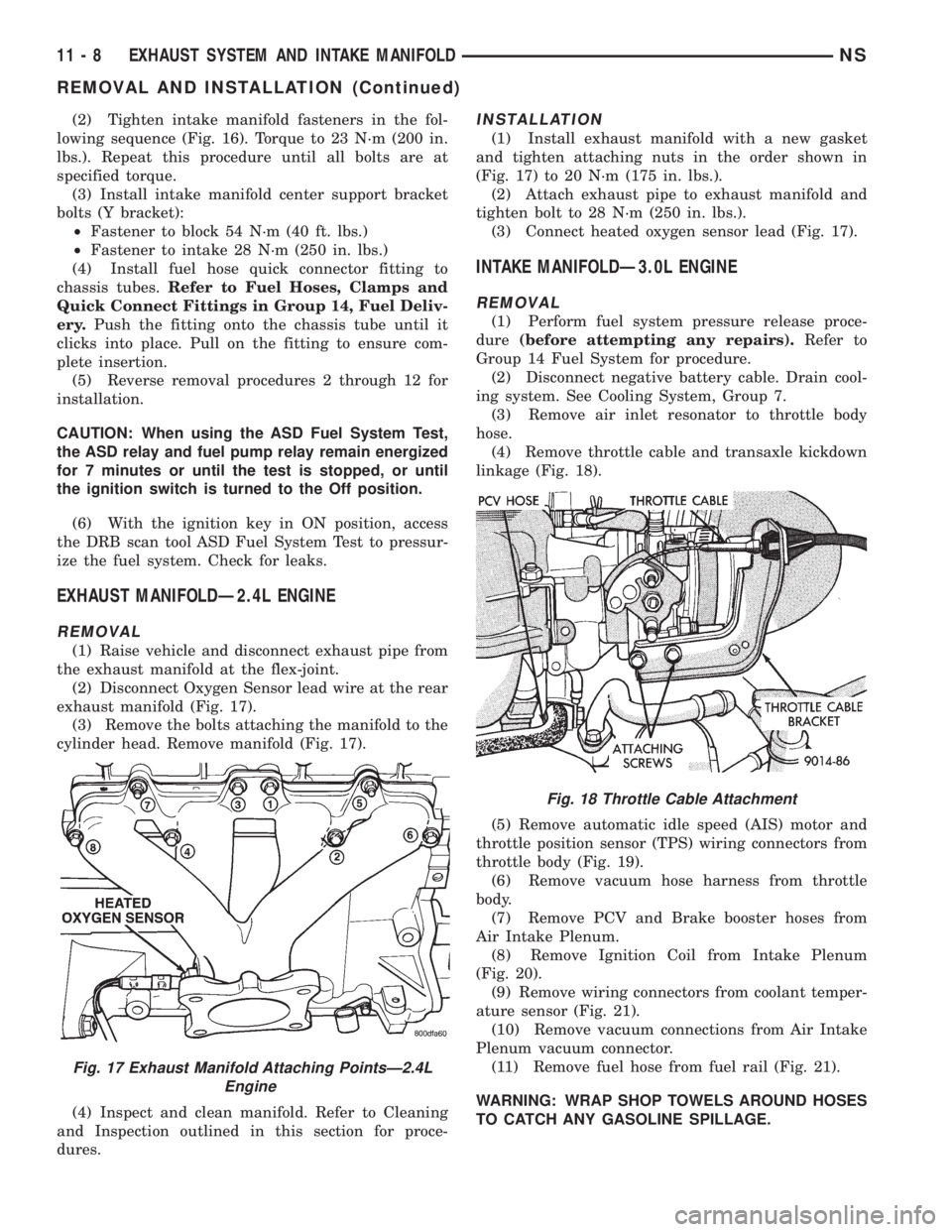
(2) Tighten intake manifold fasteners in the fol-
lowing sequence (Fig. 16). Torque to 23 N´m (200 in.
lbs.). Repeat this procedure until all bolts are at
specified torque.
(3) Install intake manifold center support bracket
bolts (Y bracket):
²Fastener to block 54 N´m (40 ft. lbs.)
²Fastener to intake 28 N´m (250 in. lbs.)
(4) Install fuel hose quick connector fitting to
chassis tubes.Refer to Fuel Hoses, Clamps and
Quick Connect Fittings in Group 14, Fuel Deliv-
ery.Push the fitting onto the chassis tube until it
clicks into place. Pull on the fitting to ensure com-
plete insertion.
(5) Reverse removal procedures 2 through 12 for
installation.
CAUTION: When using the ASD Fuel System Test,
the ASD relay and fuel pump relay remain energized
for 7 minutes or until the test is stopped, or until
the ignition switch is turned to the Off position.
(6) With the ignition key in ON position, access
the DRB scan tool ASD Fuel System Test to pressur-
ize the fuel system. Check for leaks.
EXHAUST MANIFOLDÐ2.4L ENGINE
REMOVAL
(1) Raise vehicle and disconnect exhaust pipe from
the exhaust manifold at the flex-joint.
(2) Disconnect Oxygen Sensor lead wire at the rear
exhaust manifold (Fig. 17).
(3) Remove the bolts attaching the manifold to the
cylinder head. Remove manifold (Fig. 17).
(4) Inspect and clean manifold. Refer to Cleaning
and Inspection outlined in this section for proce-
dures.
INSTALLATION
(1) Install exhaust manifold with a new gasket
and tighten attaching nuts in the order shown in
(Fig. 17) to 20 N´m (175 in. lbs.).
(2) Attach exhaust pipe to exhaust manifold and
tighten bolt to 28 N´m (250 in. lbs.).
(3) Connect heated oxygen sensor lead (Fig. 17).
INTAKE MANIFOLDÐ3.0L ENGINE
REMOVAL
(1) Perform fuel system pressure release proce-
dure(before attempting any repairs).Refer to
Group 14 Fuel System for procedure.
(2) Disconnect negative battery cable. Drain cool-
ing system. See Cooling System, Group 7.
(3) Remove air inlet resonator to throttle body
hose.
(4) Remove throttle cable and transaxle kickdown
linkage (Fig. 18).
(5) Remove automatic idle speed (AIS) motor and
throttle position sensor (TPS) wiring connectors from
throttle body (Fig. 19).
(6) Remove vacuum hose harness from throttle
body.
(7) Remove PCV and Brake booster hoses from
Air Intake Plenum.
(8) Remove Ignition Coil from Intake Plenum
(Fig. 20).
(9) Remove wiring connectors from coolant temper-
ature sensor (Fig. 21).
(10) Remove vacuum connections from Air Intake
Plenum vacuum connector.
(11) Remove fuel hose from fuel rail (Fig. 21).
WARNING: WRAP SHOP TOWELS AROUND HOSES
TO CATCH ANY GASOLINE SPILLAGE.
Fig. 17 Exhaust Manifold Attaching PointsÐ2.4L
Engine
Fig. 18 Throttle Cable Attachment
11 - 8 EXHAUST SYSTEM AND INTAKE MANIFOLDNS
REMOVAL AND INSTALLATION (Continued)
Page 1271 of 1938
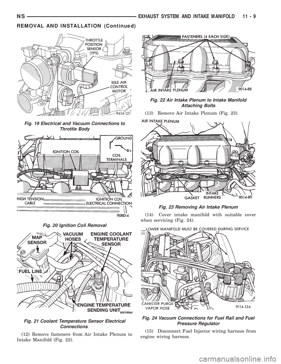
(12) Remove fasteners from Air Intake Plenum to
Intake Manifold (Fig. 22).(13) Remove Air Intake Plenum (Fig. 23).
(14) Cover intake manifold with suitable cover
when servicing (Fig. 24).
(15) Disconnect Fuel Injector wiring harness from
engine wiring harness.
Fig. 19 Electrical and Vacuum Connections to
Throttle Body
Fig. 20 Ignition Coil Removal
Fig. 21 Coolant Temperature Sensor Electrical
Connections
Fig. 22 Air Intake Plenum to Intake Manifold
Attaching Bolts
Fig. 23 Removing Air Intake Plenum
Fig. 24 Vacuum Connections for Fuel Rail and Fuel
Pressure Regulator
NSEXHAUST SYSTEM AND INTAKE MANIFOLD 11 - 9
REMOVAL AND INSTALLATION (Continued)
Page 1274 of 1938
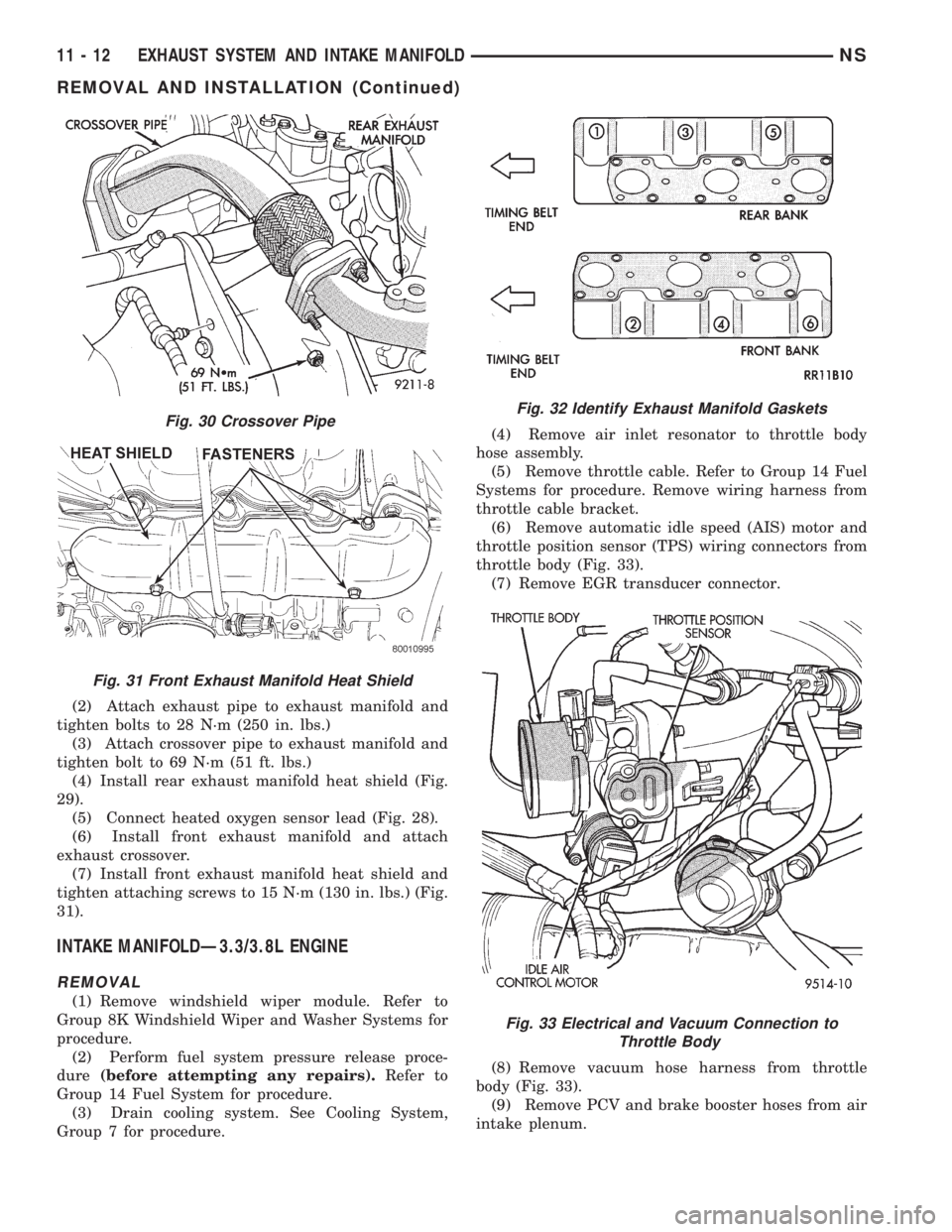
(2) Attach exhaust pipe to exhaust manifold and
tighten bolts to 28 N´m (250 in. lbs.)
(3) Attach crossover pipe to exhaust manifold and
tighten bolt to 69 N´m (51 ft. lbs.)
(4) Install rear exhaust manifold heat shield (Fig.
29).
(5) Connect heated oxygen sensor lead (Fig. 28).
(6) Install front exhaust manifold and attach
exhaust crossover.
(7) Install front exhaust manifold heat shield and
tighten attaching screws to 15 N´m (130 in. lbs.) (Fig.
31).
INTAKE MANIFOLDÐ3.3/3.8L ENGINE
REMOVAL
(1) Remove windshield wiper module. Refer to
Group 8K Windshield Wiper and Washer Systems for
procedure.
(2) Perform fuel system pressure release proce-
dure(before attempting any repairs).Refer to
Group 14 Fuel System for procedure.
(3) Drain cooling system. See Cooling System,
Group 7 for procedure.(4) Remove air inlet resonator to throttle body
hose assembly.
(5) Remove throttle cable. Refer to Group 14 Fuel
Systems for procedure. Remove wiring harness from
throttle cable bracket.
(6) Remove automatic idle speed (AIS) motor and
throttle position sensor (TPS) wiring connectors from
throttle body (Fig. 33).
(7) Remove EGR transducer connector.
(8) Remove vacuum hose harness from throttle
body (Fig. 33).
(9) Remove PCV and brake booster hoses from air
intake plenum.
Fig. 30 Crossover Pipe
Fig. 31 Front Exhaust Manifold Heat Shield
Fig. 32 Identify Exhaust Manifold Gaskets
Fig. 33 Electrical and Vacuum Connection to
Throttle Body
11 - 12 EXHAUST SYSTEM AND INTAKE MANIFOLDNS
REMOVAL AND INSTALLATION (Continued)
Page 1298 of 1938
FUEL DELIVERY SYSTEM
INDEX
page page
DESCRIPTION AND OPERATION
FUEL DELIVERY SYSTEM.................. 4
FUEL INJECTORS........................ 5
FUEL LEVEL SENSOR..................... 5
FUEL PRESSURE REGULATOR.............. 5
FUEL PUMP MODULE..................... 4
FUEL TANK............................. 5
PRESSURE-VACUUM FILLER CAP........... 6
QUICK-CONNECT FITTINGS................ 6
DIAGNOSIS AND TESTING
FUEL INJECTORS........................ 9
FUEL LEVEL SENSOR..................... 9
FUEL PUMP PRESSURE TEST 2.4/3.3/3.8L..... 6
SERVICE PROCEDURES
FUEL SYSTEM PRESSURE RELEASE
PROCEDUREÐ2.4/3.3/3.8L............... 11
FUEL SYSTEM PRESSURE RELEASE
PROCEDUREÐ3.0L ENGINE............. 11
HOSES AND CLAMPS.................... 12QUICK-CONNECT FITTINGS............... 12
REMOVAL AND INSTALLATION
ACCELERATOR PEDAL................... 26
FUEL FILTER........................... 12
FUEL INJECTOR RAILÐ2.4L............... 18
FUEL INJECTOR RAILÐ3.0L............... 19
FUEL INJECTOR RAILÐ3.3/3.8L............ 21
FUEL INJECTORSÐ3.0L.................. 25
FUEL INJECTORÐ2.4L................... 24
FUEL INJECTORÐ3.3/3.8L................. 26
FUEL LEVEL SENSOR.................... 15
FUEL PRESSURE REGULATOR............. 14
FUEL PUMP INLET STRAINER............. 15
FUEL PUMP MODULE.................... 13
FUEL TANK............................ 17
THROTTLE CABLE...................... 27
SPECIFICATIONS
FUEL TANK CAPACITY................... 28
TORQUE.............................. 28
DESCRIPTION AND OPERATION
FUEL DELIVERY SYSTEM
The front wheel drive van uses a plastic fuel tank
located on the left side of the vehicle.
The Fuel Delivery System consists of: the electric
fuel pump module, fuel filter, tubes/lines/hoses, fuel
rail, and fuel injectors.
The in-tank fuel pump module contains the fuel
pump and pressure regulator. The pump is serviced
as part of the fuel pump module. Refer to Fuel Pump
Module.
The fuel filter is a replaceable in-line filter. The fil-
ter attaches to a bracket mounted on top of the fuel
tank. Refer to the Maintenance Schedules in the
Introduction section of this manual for recommended
fuel filter replacement intervals.
A returnless fuel system is used on all vehicles.
Fuel is returned through the fuel pump module and
back to the fuel tank. A separate fuel return line
from the tank to the engine is no longer used.
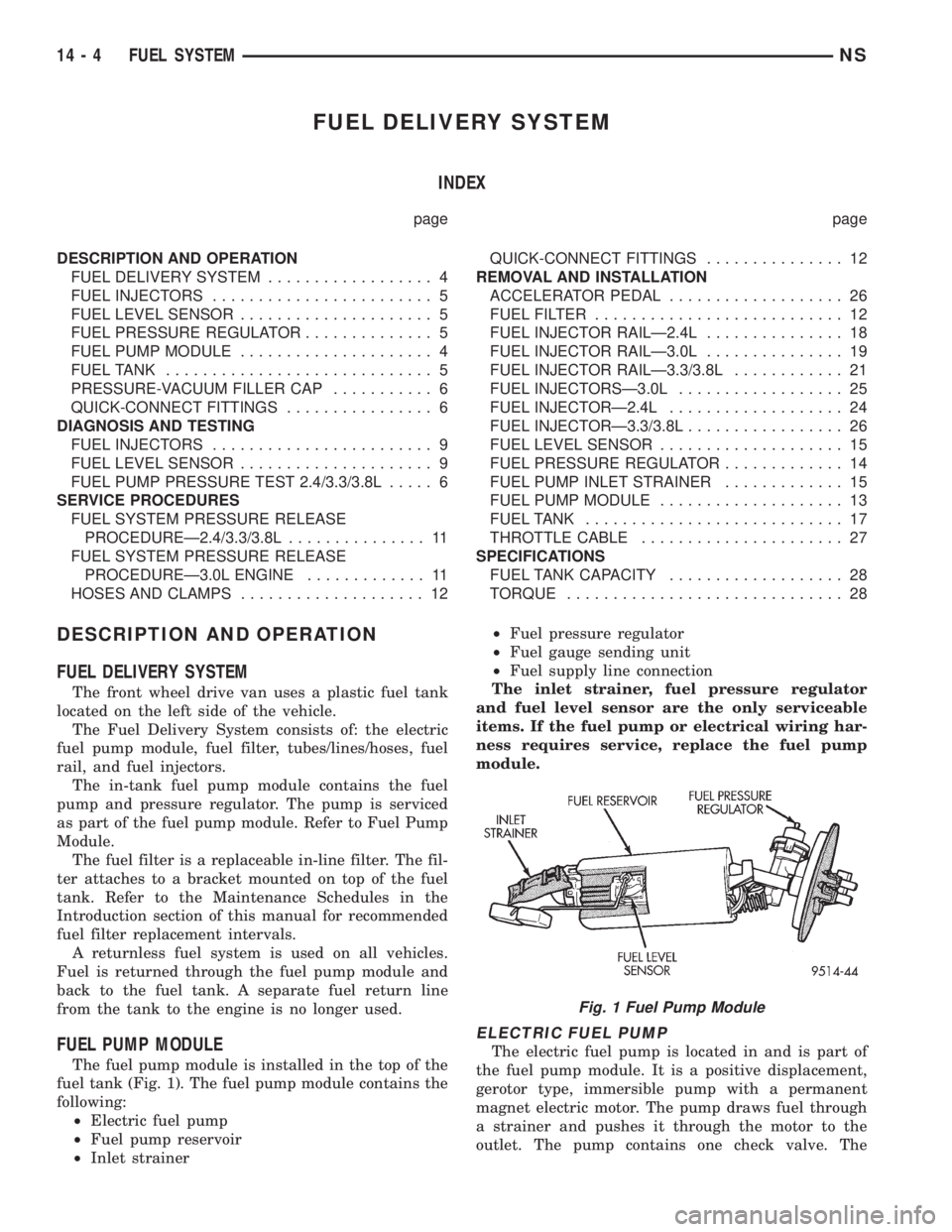
FUEL PUMP MODULE
The fuel pump module is installed in the top of the
fuel tank (Fig. 1). The fuel pump module contains the
following:
²Electric fuel pump
²Fuel pump reservoir
²Inlet strainer²Fuel pressure regulator
²Fuel gauge sending unit
²Fuel supply line connection
The inlet strainer, fuel pressure regulator
and fuel level sensor are the only serviceable
items. If the fuel pump or electrical wiring har-
ness requires service, replace the fuel pump
module.
ELECTRIC FUEL PUMP
The electric fuel pump is located in and is part of
the fuel pump module. It is a positive displacement,
gerotor type, immersible pump with a permanent
magnet electric motor. The pump draws fuel through
a strainer and pushes it through the motor to the
outlet. The pump contains one check valve. The
Fig. 1 Fuel Pump Module
14 - 4 FUEL SYSTEMNS