1996 CHRYSLER VOYAGER display
[x] Cancel search: displayPage 1875 of 1938
²Set A/C to ON, if A/C Clutch does not engage
make sure Fail Codes 5 and 6 are cleared.To clear
the error code 5 and 6 the evaporator probe and/or
the wiring repair needs to be completed. Then, press
and hold the intermittent wipe button for 5 seconds.
²Run Diagnostics (Depress REAR WIPER and
REAR WASH)
²When Diagnostics is complete, Cycle to Level 4.
Display Sequence is as follows:
²REAR WIPER LED will display the Level
²INTERMITTENT LED will display ten's digit
²Short Pause
²INTERMITTENT LED will display the one's
digit.
The HVAC control module will continue to cycle
the Level and then Temperature until the level is
changed or Calibration Diagnostics and Cooldown
test is exited.
HVAC CONTROL DIAGNOSTIC CONDITIONS
For wiring circuits, wiring connectors, and Pin
numbers, refer to Group 8W, Wiring Diagrams.
After calibration, Rear Wiper LED flashing
once, Intermittent LED not flashing.
The system has passed calibration. Press the Rear
Wiper button to exit calibration.
After calibration, Rear Wiper LED flashing
once, Intermittent LED flashing once. The
mode actuator did not reach defrost position.
(1) Using a voltmeter, check the mode door actua-
tor wiring connector. Check Pin 1 for battery voltage.
Move the HVAC control from the defrost to panel
position, and check Pin 6 voltage it should change
from 0.5 - 1 volts to 3.5 - 4.5 volts. If voltage is OK,
go to Step 2. If not OK, check for loose or corroded
connector, open or shorted circuit and repair as nec-
essary.
(2) Remove actuator, and check if the gear pins are
in the correct track on cam or if they are binding. If
OK, go to Step 3. If not OK, repair as necessary.
(3) Check for binding door, if door is binding repair
as necessary. If gears and door are OK, replace
actuator.
(4) Once repairs are completed repeat the Calibra-
tion Diagnostic and Cooldown test. Repeating the
test is necessary to clear the fault codes.
After calibration, Rear Wiper LED flashing
once, Intermittent LED flashing twice. The
mode actuator did not reach panel position.
(1) Using a voltmeter, check the mode door actua-
tor wiring connector. Check Pin 1 for battery voltage.
Move the HVAC control from panel to defrost posi-
tion, and check Pin 6 voltage it should change from
3.5 - 4.5 volts to 0.5 - 1 volts. If voltage is OK, go toStep 2. If not OK, check for loose or corroded connec-
tor, open or shorted circuit and repair as necessary.
(2) Remove actuator, and check if the gear pins are
in the correct cam track or binding. If OK, go to Step
3. If not OK, repair as necessary.
(3) Check for binding door, if door is binding repair
as necessary. If gears and door are OK, replace
actuator.
(4) Once repairs are completed repeat the Calibra-
tion Diagnostic and Cooldown test. Repeating the
test is necessary to clear the fault codes.
After calibration, Rear Wiper LED flashing
once, Intermittent LED flashing three times.
The main temperature actuator/passenger
temperature actuator on a zone system did
not reach cold stop.
(1) Check if the correct HVAC control module was
used.
(2) Using a voltmeter, check the temperature door
actuator wiring connector. Check Pin 1 for battery
voltage. Move the HVAC control from the cold to hot
position, and check Pin 5 voltage it should change
from 0.5 - 4 volts to 3.5 - 4.5 volts. If voltage is OK,
go to Step 3. If not OK, check for loose or corroded
connector, open or shorted circuit and repair as nec-
essary.
(3) Remove actuator, and check if gear pins are in
the correct cam track or binding. If OK, go to Step 4.
If not OK, repair as necessary.
(4) Check for binding door, if door is binding repair
as necessary. If gears and door are OK, replace
actuator.
(5) Once repairs are completed repeat the Calibra-
tion Diagnostic and Cooldown test. Repeating the
test is necessary to clear the fault codes.
After calibration, Rear Wiper LED flashing
once, Intermittent LED flashing four times.
The main temperature actuator/passenger
temperature actuator on a zone system did
not reach hot stop.
(1) Check if the correct HVAC control module was
used.
(2) Using a voltmeter, check the temperature door
actuator wiring connector. Check Pin 1 for battery
voltage. Move the HVAC control from hot to cold
position and check Pin 5 voltage it should change
from 3.5 -4.5 volts 0.5 - 1.5 volts. If voltage is OK, go
to Step 3. If not OK, check for loose or corroded con-
nector, open or shorted circuit and repair as neces-
sary.
(3) Remove actuator, and check if the gear pins are
in the correct track on cam or if they are binding. If
OK, go to Step 4. If not OK, repair as necessary.
NS/GSHEATING AND AIR CONDITIONING 24 - 9
DIAGNOSIS AND TESTING (Continued)
Page 1877 of 1938
²No charge
²Compressor not operating
Verify that the test was done with the evaporator
at room temperature. The test consists of starting
the compressor and measuring the time it takes for
the evaporator temperature to fall 7ÉC (20ÉF). If the
compressor has been running, the evaporator is cold
already and will not be capable of falling 7ÉC (20ÉF).
If the test was run with a cold evaporator, turn A/C
off and turn the blower motor switch to high position
for 3 to 5 minutes till the evaporator is to room tem-
perature. Then repeat the Calibration Diagnostic and
Cooldown test.
If refrigerant system is performing properly and
the system will not pass test. Repeat the Calibration
Diagnostic and Cooldown test to determine if the
evaporator temperature FIN sensor has developed an
open or a short circuit. If the HVAC control module
still passes Calibration test, verify Cooldown test
manually with a pocket thermometer. The outlet air
temperature must drop at least 7ÉC (20ÉF) within
two minutes. If the vehicle passes with the manual
thermometer, take HVAC control to level 4 (evapora-
tor probe temperature readout) and repeat the
Cooldown test. Ensure the evaporator is at room tem-
perature before starting test. Check if evaporator
probe will drop the temperature 7ÉC (20ÉF) in two
minutes. If the Evaporator Probe is found to be
faulty, check that the sensor is positioned in the
evaporator fins properly. If not, correct and repeat
test. If OK, replace the evaporator probe.
Once the repairs are completed, repeat the Calibra-
tion Diagnostic and Cooldown test. Repeating the
test is necessary to clear the fault codes.
A/C PERFORMANCE TEST
The air conditioning system is designed to remove
heat and humidity from the air entering the passen-
ger compartment. The evaporator, located in the
heater A/C unit, is cooled to temperatures near the
freezing point. As warm damp air passes over the
fins in the evaporator, moisture in the air condenses
to water, dehumidifying the air. Condensation on the
evaporator fins reduces the evaporators ability to
absorb heat. During periods of high heat and humid-
ity, an air conditioning system will be less effective.
With the instrument control set to RECIRC, only air
from the passenger compartment passes through the
evaporator. As the passenger compartment air dehu-
midifies, A/C performance levels rise.
PERFORMANCE TEST PROCEDURE
Review Safety Precautions and Warnings in this
group before proceeding with this procedure. Air tem-
perature in test room and on vehicle must be 21É C
(70ÉF) minimum for this test.
NOTE: When connecting the service equipment
coupling to the line fitting, verify that the valve of
the coupling is fully closed. This will reduce the
amount of effort required to make the connection.
(1) Connect a tachometer and manifold gauge set.
(2) Set control to A/C, RECIRC, and PANEL, tem-
perature lever on full cool and blower on high.
(3) Start engine and hold at 1000 rpm with A/C
clutch engaged.
(4) Engine should be warmed up with doors and
windows closed.
(5) Insert a thermometer in the left center A/C
outlet and operate the engine for five minutes. The
A/C clutch may cycle depending on ambient condi-
tions.
(6) With the A/C clutch engaged, compare the dis-
charge air temperature to the A/C Performance Tem-
peratures chart (Fig. 7).
(7) If the discharge air temperature fails to meet
the specifications in the performance temperature
chart. Refer to the Refrigerant Service Procedures for
further diagnosis.
A/C PRESSURE TRANSDUCER
The work area temperature must not be below
10ÉC (50ÉF) to test the compressor clutch circuit.
Before starting to test the transducer ensure that the
wire connector is clean of corrosion and connected
properly.
(1) With gear selector in park or neutral and park
brake set, start engine and allow to idle.
(2) Install scan tool (DRB):
²Go to main menu
²Select stand alone scan tool (DRB)
²Select refer to the proper year diagnostics
²Select climate control
²Select sensor display
²Select A/C high side volts
For A/C system to operate a voltage between .451
(Low Pressure Cutout) to 4.519 (High Pressure Cut-
out is required. Voltages outside this range indicate a
low or high pressure condition andwill notallow
the compressor to cycle.
The following chart denotes voltages and the
appropriate condition(s):
NS/GSHEATING AND AIR CONDITIONING 24 - 11
DIAGNOSIS AND TESTING (Continued)
Page 1881 of 1938

POSSIBLE LOCATIONS OR CAUSE OF
OBSTRUCTED COOLANT FLOW
(1) Pinched or kinked heater hoses.
(2) Improper heater hose routing.
(3) Plugged heater hoses or supply and return
ports at cooling system connections, refer to Group 7,
Cooling System.
(4) Plugged heater core.
(5) Air locked heater core.
(6) If coolant flow is verified and outlet tempera-
ture is insufficient, a mechanical problem may exist.
POSSIBLE LOCATION OR CAUSE OF
INSUFFICIENT HEAT
(1) Obstructed cowl air intake.
(2) Obstructed heater system outlets.
(3) Blend-air door not functioning properly.
TEMPERATURE CONTROL
If temperature cannot be adjusted with the TEMP
lever on the control panel, the following could require
service:
(1) Blend-air door binding.
(2) Faulty blend-air door motor.
(3) Improper engine coolant temperature.
(4) Faulty Instrument Panel Control.
SYSTEM CHARGE LEVEL TEST
The procedure below should be used to check
and/or fill the refrigerant charge in the air condition-
ing system.
NOTE: The amount of R134a refrigerant that the air
conditioning system holds is 0.96 kg (34 oz. or 2.13
lbs.).
NOTE: Low Charge, condition may be described
as:
²Loss of A/C performance
²Fog from A/C outlets
²evaporator may have a HISS sound
There are two different ways the system can be
tested:
²With a scan tool (DRB), thermocouple and the
Charge Determination Graph. Use the scan tool
(DRB) diagnostic topic: Engine±System Monitors, A/C
Pressure.
²Using a manifold gauge set, a thermocouple and
the Charge Determination Graph.
It is recommended to use the gauges or reclaim/re-
cycle equipment.
WARNING: AVOID BREATHING A/C REFRIGERANT
AND LUBRICANT VAPOR OR MIST. EXPOSURE MAY
IRRITATE EYES, NOSE AND THROAT. USE ONLY
APPROVED SERVICE EQUIPMENT MEETING SAEREQUIREMENTS TO DISCHARGE R-134a SYSTEM. IF
ACCIDENTAL SYSTEM DISCHARGE OCCURS, VEN-
TILATE WORK AREA BEFORE RESUMING SERVICE.
R-134a SERVICE EQUIPMENT OR VEHICLE A/C
SYSTEM SHOULD NOT BE PRESSURE TESTED OR
LEAK TESTED WITH COMPRESSED AIR. SOME
MIXTURES OF AIR/R-134a HAVE BEEN SHOWN TO
BE COMBUSTIBLE AT ELEVATED PRESSURES.
THESE MIXTURES ARE POTENTIALLY DANGER-
OUS AND MAY RESULT IN FIRE OR EXPLOSION
CAUSING INJURY OR PROPERTY DAMAGE.
(1) Establish your preferred method of measuring
liquid line pressure. Use a manifold gauge set or a
DRB scan tool.
(2) A
ttach a clamp-on thermocouple (Professional
Service Equipment 66-324-0014 or 80PK-1A) or equiv-
alent to the liquid line. It must be placed as close to
the A/C Pressure Transducer as possible to observe liq-
uid line temperature. Refer to ªThermocouple Probeº in
this section for more information on probe.
(3) The vehicle must be in the following modes:
²Transaxle in Park
²Engine Idling at 700 rpm
²A/C Controls Set to Outside Air
²Panel Mode
²Full Cool
²High Blower motor, (vehicle equipped with rear
A/C turn rear blower motor ON HIGH)
²A/C Button in the ON position
²Vehicle Windows Open.
²Recirc. button turned OFF
(4) Operate system for a couple of minutes to allow
the system to stabilize.
(5) Set system pressure to about 1793 kPa (260
psi) by placing a piece of cardboard over part of the
front side of the condenser. To place cardboard prop-
erly, remove the upper radiator-condenser cover.
Insert cardboard between condenser and radiator
front. This will maintain a constant pressure.
(6) Observe Liquid Line pressure and Liquid line
temperature. Using theCharge Determination
Chartdetermine where the system is currently oper-
ating. If the system is in the undercharged region,
ADD 0.057 Kg. (2 oz.) to the system and recheck
readings. If the system is in the overcharged region,
RECLAIM 0.057 Kg. (2 oz.) from the system and
recheck readings. Continue this process until the sys-
tem readings are in the proper charge area on the
Charge Determination Chart.
(7) The same procedure can be performed using
the scan tool (DRB). To determine liquid line pres-
sure, attach the scan tool, go to System Moni-
tors±A/C Pressure. Observe liquid line pressure from
A/C Pressure Transducer on digital display and digi-
tal thermometer. Refer toCharge Determination
Chartand determine where the system is operating.
NS/GSHEATING AND AIR CONDITIONING 24 - 15
DIAGNOSIS AND TESTING (Continued)
Page 1905 of 1938
EMISSION CONTROL SYSTEMS
CONTENTS
page page
EVAPORATIVE EMISSION CONTROLS........ 13
EXHAUST GAS RECIRCULATION (EGR)
SYSTEM.............................. 18ON-BOARD DIAGNOSTICS.................. 1
ON-BOARD DIAGNOSTICS
INDEX
page page
GENERAL INFORMATION
SYSTEM DESCRIPTION................... 1
DESCRIPTION AND OPERATION
CIRCUIT ACTUATION TEST MODE........... 3
COMPONENT MONITORS................. 10
DIAGNOSTIC TROUBLE CODES............. 3
HIGH AND LOW LIMITS................... 11LOAD VALUE........................... 12
MALFUNCTION INDICATOR LAMP (MIL)....... 1
MONITORED SYSTEMS.................... 8
NON-MONITORED CIRCUITS............... 11
STATE DISPLAY TEST MODE............... 2
TRIP DEFINITION........................ 10
GENERAL INFORMATION
SYSTEM DESCRIPTION
The Powertrain Control Module (PCM) monitors
many different circuits in the fuel injection, ignition,
emission and engine systems. If the PCM senses a
problem with a monitored circuit often enough to
indicate an actual problem, it stores a Diagnostic
Trouble Code (DTC) in the PCM's memory. If the
code applies to a non-emissions related component or
system, and the problem is repaired or ceases to
exist, the PCM cancels the code after 40 warmup
cycles. Diagnostic trouble codes that affect vehicle
emissions illuminate the Malfunction Indicator Lamp
(MIL). Refer to Malfunction Indicator Lamp in this
section.
Certain criteria must be met before the PCM
stores a DTC in memory. The criteria may be a spe-
cific range of engine RPM, engine temperature,
and/or input voltage to the PCM.
The PCM might not store a DTC for a monitored
circuit even though a malfunction has occurred. This
may happen because one of the DTC criteria for the
circuit has not been met.For example, assume the
diagnostic trouble code criteria requires the PCM to
monitor the circuit only when the engine operates
between 750 and 2000 RPM. Suppose the sensor'soutput circuit shorts to ground when engine operates
above 2400 RPM (resulting in 0 volt input to the
PCM). Because the condition happens at an engine
speed above the maximum threshold (2000 rpm), the
PCM will not store a DTC.
There are several operating conditions for which
the PCM monitors and sets DTC's. Refer to Moni-
tored Systems, Components, and Non-Monitored Cir-
cuits in this section.
NOTE: Various diagnostic procedures may actually
cause a diagnostic monitor to set a DTC. For
instance, pulling a spark plug wire to perform a
spark test may set the misfire code. When a repair
is completed and verified, use the DRB scan tool to
erase all DTC's and extinguish the MIL.
Technicians can display stored DTC's by using the
DRB scan tool. Refer to Diagnostic Trouble Codes in
this section. For DTC information, refer to charts in
this section.
DESCRIPTION AND OPERATION
MALFUNCTION INDICATOR LAMP (MIL)
As a functional test, the Malfunction Indicator
Lamp (MIL) illuminates at key-on before engine
NSEMISSION CONTROL SYSTEMS 25 - 1
Page 1906 of 1938
cranking. Whenever the Powertrain Control Module
(PCM) sets a Diagnostic Trouble Code (DTC) that
affects vehicle emissions, it illuminates the MIL. If a
problem is detected, the PCM sends a message over
the CCD Bus to the instrument cluster to illuminate
the lamp. The PCM illuminates the MIL only for
DTC's that affect vehicle emissions. The MIL stays
on continuously when the PCM has entered a
Limp-In mode or identified a failed emission compo-
nent or system. The MIL remains on until the DTC
is erased. Refer to the Diagnostic Trouble Code
charts in this group for emission related codes.
Also, the MIL either flashes or illuminates contin-
uously when the PCM detects active engine misfire.
Refer to Misfire Monitoring in this section.
Additionally, the PCM may reset (turn off) the MIL
when one of the following occur:
²PCM does not detect the malfunction for 3 con-
secutive trips (except misfire and fuel system moni-
tors).
²PCM does not detect a malfunction while per-
forming three successive engine misfire or fuel sys-
tem tests. The PCM performs these tests while the
engine is operating within6375 RPM of and within
10 % of the load of the operating condition at which
the malfunction was first detected.
STATE DISPLAY TEST MODE
The switch inputs to the Powertrain Control Mod-
ule (PCM) have two recognized states; HIGH and
LOW. For this reason, the PCM cannot recognize the
difference between a selected switch position versus
an open circuit, a short circuit, or a defective switch.
If the State Display screen shows the change from
HIGH to LOW or LOW to HIGH, assume the entire
switch circuit to the PCM functions properly. From
the state display screen, access either State Display
Inputs and Outputs or State Display Sensors.
STATE DISPLAY INPUTS AND OUTPUTS
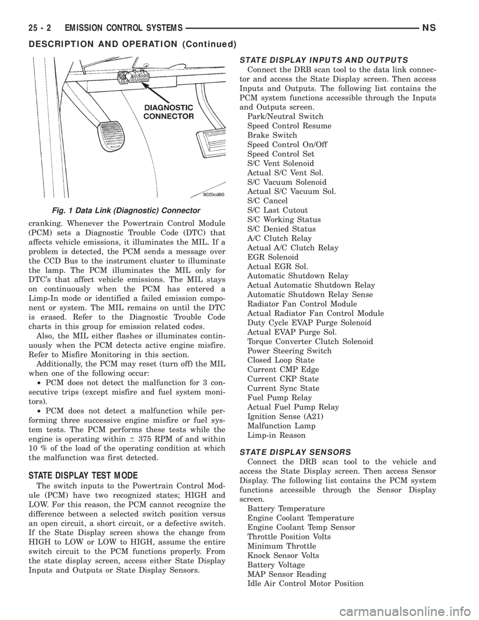
Connect the DRB scan tool to the data link connec-
tor and access the State Display screen. Then access
Inputs and Outputs. The following list contains the
PCM system functions accessible through the Inputs
and Outputs screen.
Park/Neutral Switch
Speed Control Resume
Brake Switch
Speed Control On/Off
Speed Control Set
S/C Vent Solenoid
Actual S/C Vent Sol.
S/C Vacuum Solenoid
Actual S/C Vacuum Sol.
S/C Cancel
S/C Last Cutout
S/C Working Status
S/C Denied Status
A/C Clutch Relay
Actual A/C Clutch Relay
EGR Solenoid
Actual EGR Sol.
Automatic Shutdown Relay
Actual Automatic Shutdown Relay
Automatic Shutdown Relay Sense
Radiator Fan Control Module
Actual Radiator Fan Control Module
Duty Cycle EVAP Purge Solenoid
Actual EVAP Purge Sol.
Torque Converter Clutch Solenoid
Power Steering Switch
Closed Loop State
Current CMP Edge
Current CKP State
Current Sync State
Fuel Pump Relay
Actual Fuel Pump Relay
Ignition Sense (A21)
Malfunction Lamp
Limp-in Reason
STATE DISPLAY SENSORS
Connect the DRB scan tool to the vehicle and
access the State Display screen. Then access Sensor
Display. The following list contains the PCM system
functions accessible through the Sensor Display
screen.
Battery Temperature
Engine Coolant Temperature
Engine Coolant Temp Sensor
Throttle Position Volts
Minimum Throttle
Knock Sensor Volts
Battery Voltage
MAP Sensor Reading
Idle Air Control Motor Position
Fig. 1 Data Link (Diagnostic) Connector
25 - 2 EMISSION CONTROL SYSTEMSNS
DESCRIPTION AND OPERATION (Continued)
Page 1908 of 1938
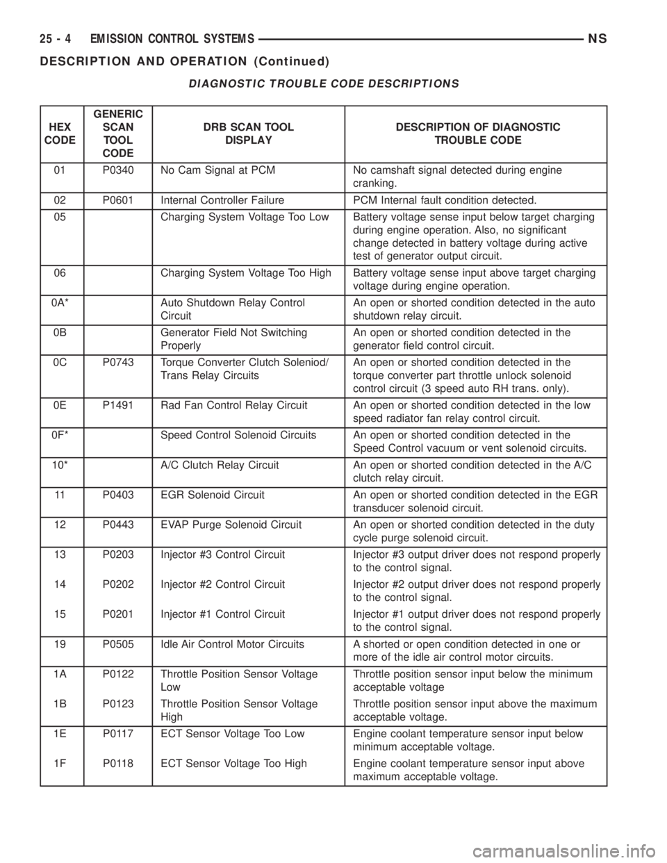
DIAGNOSTIC TROUBLE CODE DESCRIPTIONS
HEX
CODEGENERIC
SCAN
TOOL
CODEDRB SCAN TOOL
DISPLAYDESCRIPTION OF DIAGNOSTIC
TROUBLE CODE
01 P0340 No Cam Signal at PCM No camshaft signal detected during engine
cranking.
02 P0601 Internal Controller Failure PCM Internal fault condition detected.
05 Charging System Voltage Too Low Battery voltage sense input below target charging
during engine operation. Also, no significant
change detected in battery voltage during active
test of generator output circuit.
06 Charging System Voltage Too High Battery voltage sense input above target charging
voltage during engine operation.
0A* Auto Shutdown Relay Control
CircuitAn open or shorted condition detected in the auto
shutdown relay circuit.
0B Generator Field Not Switching
ProperlyAn open or shorted condition detected in the
generator field control circuit.
0C P0743 Torque Converter Clutch Soleniod/
Trans Relay CircuitsAn open or shorted condition detected in the
torque converter part throttle unlock solenoid
control circuit (3 speed auto RH trans. only).
0E P1491 Rad Fan Control Relay Circuit An open or shorted condition detected in the low
speed radiator fan relay control circuit.
0F* Speed Control Solenoid Circuits An open or shorted condition detected in the
Speed Control vacuum or vent solenoid circuits.
10* A/C Clutch Relay Circuit An open or shorted condition detected in the A/C
clutch relay circuit.
11 P0403 EGR Solenoid Circuit An open or shorted condition detected in the EGR
transducer solenoid circuit.
12 P0443 EVAP Purge Solenoid Circuit An open or shorted condition detected in the duty
cycle purge solenoid circuit.
13 P0203 Injector #3 Control Circuit Injector #3 output driver does not respond properly
to the control signal.
14 P0202 Injector #2 Control Circuit Injector #2 output driver does not respond properly
to the control signal.
15 P0201 Injector #1 Control Circuit Injector #1 output driver does not respond properly
to the control signal.
19 P0505 Idle Air Control Motor Circuits A shorted or open condition detected in one or
more of the idle air control motor circuits.
1A P0122 Throttle Position Sensor Voltage
LowThrottle position sensor input below the minimum
acceptable voltage
1B P0123 Throttle Position Sensor Voltage
HighThrottle position sensor input above the maximum
acceptable voltage.
1E P0117 ECT Sensor Voltage Too Low Engine coolant temperature sensor input below
minimum acceptable voltage.
1F P0118 ECT Sensor Voltage Too High Engine coolant temperature sensor input above
maximum acceptable voltage.
25 - 4 EMISSION CONTROL SYSTEMSNS
DESCRIPTION AND OPERATION (Continued)
Page 1909 of 1938
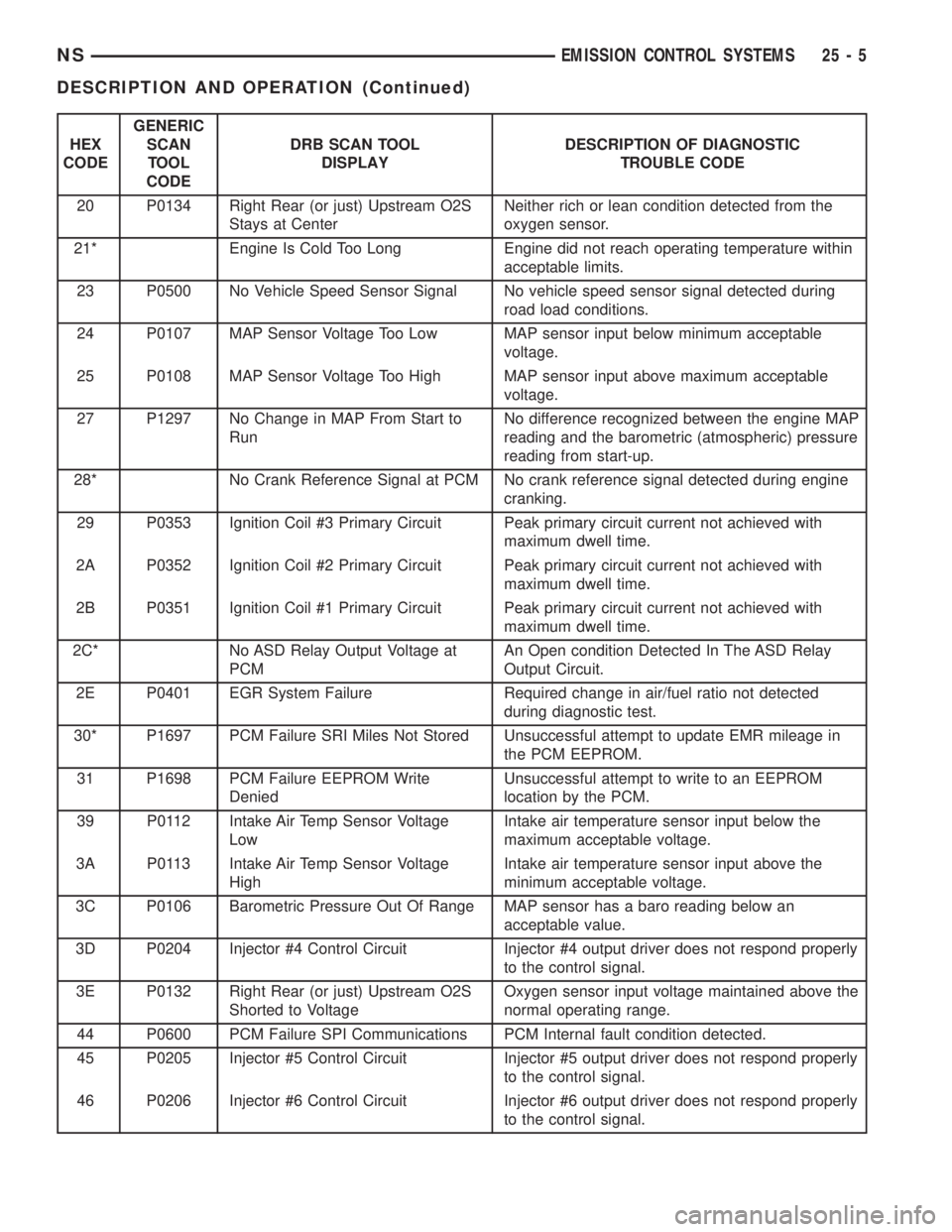
HEX
CODEGENERIC
SCAN
TOOL
CODEDRB SCAN TOOL
DISPLAYDESCRIPTION OF DIAGNOSTIC
TROUBLE CODE
20 P0134 Right Rear (or just) Upstream O2S
Stays at CenterNeither rich or lean condition detected from the
oxygen sensor.
21* Engine Is Cold Too Long Engine did not reach operating temperature within
acceptable limits.
23 P0500 No Vehicle Speed Sensor Signal No vehicle speed sensor signal detected during
road load conditions.
24 P0107 MAP Sensor Voltage Too Low MAP sensor input below minimum acceptable
voltage.
25 P0108 MAP Sensor Voltage Too High MAP sensor input above maximum acceptable
voltage.
27 P1297 No Change in MAP From Start to
RunNo difference recognized between the engine MAP
reading and the barometric (atmospheric) pressure
reading from start-up.
28* No Crank Reference Signal at PCM No crank reference signal detected during engine
cranking.
29 P0353 Ignition Coil #3 Primary Circuit Peak primary circuit current not achieved with
maximum dwell time.
2A P0352 Ignition Coil #2 Primary Circuit Peak primary circuit current not achieved with
maximum dwell time.
2B P0351 Ignition Coil #1 Primary Circuit Peak primary circuit current not achieved with
maximum dwell time.
2C* No ASD Relay Output Voltage at
PCMAn Open condition Detected In The ASD Relay
Output Circuit.
2E P0401 EGR System Failure Required change in air/fuel ratio not detected
during diagnostic test.
30* P1697 PCM Failure SRI Miles Not Stored Unsuccessful attempt to update EMR mileage in
the PCM EEPROM.
31 P1698 PCM Failure EEPROM Write
DeniedUnsuccessful attempt to write to an EEPROM
location by the PCM.
39 P0112 Intake Air Temp Sensor Voltage
LowIntake air temperature sensor input below the
maximum acceptable voltage.
3A P0113 Intake Air Temp Sensor Voltage
HighIntake air temperature sensor input above the
minimum acceptable voltage.
3C P0106 Barometric Pressure Out Of Range MAP sensor has a baro reading below an
acceptable value.
3D P0204 Injector #4 Control Circuit Injector #4 output driver does not respond properly
to the control signal.
3E P0132 Right Rear (or just) Upstream O2S
Shorted to VoltageOxygen sensor input voltage maintained above the
normal operating range.
44 P0600 PCM Failure SPI Communications PCM Internal fault condition detected.
45 P0205 Injector #5 Control Circuit Injector #5 output driver does not respond properly
to the control signal.
46 P0206 Injector #6 Control Circuit Injector #6 output driver does not respond properly
to the control signal.
NSEMISSION CONTROL SYSTEMS 25 - 5
DESCRIPTION AND OPERATION (Continued)
Page 1910 of 1938
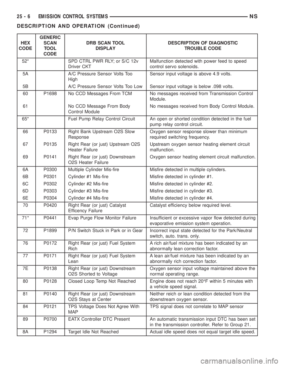
HEX
CODEGENERIC
SCAN
TOOL
CODEDRB SCAN TOOL
DISPLAYDESCRIPTION OF DIAGNOSTIC
TROUBLE CODE
52* SPD CTRL PWR RLY; or S/C 12v
Driver CKTMalfunction detected with power feed to speed
control servo solenoids.
5A A/C Pressure Sensor Volts Too
HighSensor input voltage is above 4.9 volts.
5B A/C Pressure Sensor Volts Too Low Sensor input voltage is below .098 volts.
60 P1698 No CCD Messages From TCM No messages received from Transmission Control
Module.
61 No CCD Message From Body
Control ModuleNo messages received from Body Control Module.
65* Fuel Pump Relay Control Circuit An open or shorted condition detected in the fuel
pump relay control circuit.
66 P0133 Right Bank Upstream O2S Slow
ResponseOxygen sensor response slower than minimum
required switching frequency.
67 P0135 Right Rear (or just) Upstream O2S
Heater FailureUpstream oxygen sensor heating element circuit
malfunction.
69 P0141 Right Rear (or just) Downstream
O2S Heater FailureOxygen sensor heating element circuit malfunction.
6A P0300 Multiple Cylinder Mis-fire Misfire detected in multiple cylinders.
6B P0301 Cylinder #1 Mis-fire Misfire detected in cylinder #1.
6C P0302 Cylinder #2 Mis-fire Misfire detected in cylinder #2.
6D P0303 Cylinder #3 Mis-fire Misfire detected in cylinder #3.
6E P0304 Cylinder #4 Mis-fire Misfire detected in cylinder #4.
70 P0420 Right Rear (or just) Catalyst
Efficency FailureCatalyst efficiency below required level.
71* P0441 Evap Purge Flow Monitor Failure Insufficient or excessive vapor flow detected during
evaporative emission system operation.
72 P1899 P/N Switch Stuck in Park or in Gear Incorrect input state detected for the Park/Neutral
switch, auto. trans. only.
76 P0172 Right Rear (or just) Fuel System
RichA rich air/fuel mixture has been indicated by an
abnormally lean correction factor.
77 P0171 Right Rear (or just) Fuel System
LeanA lean air/fuel mixture has been indicated by an
abnormally rich correction factor.
7E P0138 Right Rear (or just) Downstream
O2S Shorted to VoltageOxygen sensor input voltage maintained above the
normal operating range.
80 P0128 Closed Loop Temp Not Reached Engine does not reach 20ÉF within 5 minutes with
a vehicle speed signal.
81 P0140 Right Rear (or just) Downstream
O2S Stays at CenterNeither reich or lean condition detected from the
downstream oxygen sensor.
84 P0121 TPS Voltage Does Not Agree With
MAPTPS signal does not correlate to MAP sensor
89 P0700 EATX Controller DTC Present An automatic transmission input DTC has been set
in the transmission controller. Refer to Group 21.
8A P1294 Target Idle Not Reached Actual idle speed does not equal target idle speed.
25 - 6 EMISSION CONTROL SYSTEMSNS
DESCRIPTION AND OPERATION (Continued)