1996 CHRYSLER VOYAGER radiator cap
[x] Cancel search: radiator capPage 1476 of 1938
GENERAL INFORMATION
31TH TRANSAXLE
NOTE: Safety goggles should be worn at all times
when working on these transaxles.
This transaxle combines torque converter, three
speed transmission, final drive gearing, and differen-
tial into a front wheel drive system. The identifica-
tion markings and usage of the transaxle are charted
in Diagnosis and Tests.
NOTE: Transaxle operation requirements are differ-
ent for each vehicle and engine combination. Some
internal parts will be different to provide for this.
Therefore, when replacing parts, refer to the seven
digit part number stamped on rear of the transaxle
oil pan flange.
Within this transaxle, there are three primary
areas:
(1) Main center line plus valve body.
(2) Transfer shaft center line (includes governor
and parking sprag).
(3) Differential center line.
(4) Center distances between the main rotating
parts in these three areas are held precise to main-
tain a low noise level.
(5) The torque converter, transaxle area, and dif-
ferential are housed in an integral aluminum die
casting.The differential oil sump is common
with the transaxle sump. Separate filling of the
differential is NOT necessary.
(6) The torque converter is attached to the crank-
shaft through a flexible driving plate. Cooling of the
converter is accomplished by circulating the tran-
saxle fluid through a remote cooler. There are two
types of coolers used. An oil-to-water type cooler
located in the radiator side tank and/or an oil-to air
heat exchanger. The torque converter assembly is a
sealed unit that cannot be disassembled.
(7) The transaxle fluid is filtered by an internal fil-
ter attached to the lower side of the valve body
assembly.
(8) Engine torque is transmitted to the torque con-
verter then, through the input shaft to multiple-disc
clutches in the transaxle. The power flow depends on
the application of the clutches and bands. Refer to
Elements in Use Chart in Diagnosis and Tests sec-
tion.
(9) The transaxle consists of:
²Two multiple-disc clutches
²An overrunning clutch
²Two servos
²A hydraulic accumulator
²Two bands²Two planetary gear sets
This provides three forward ratios and a reverse
ratio. The common sun gear of the planetary gear
sets is connected to the front clutch by a driving
shell. The drive shell is splined to the sun gear and
front clutch retainer. The hydraulic system consists
of an oil pump, and a single valve body which con-
tains all of the valves except the governor valves.
The transaxle sump and differential sump are both
vented through the dipstick. Output torque from the
main center line is delivered through helical gears to
the transfer shaft. This gear set is a factor of the
final drive (axle) ratio. The shaft also carries the gov-
ernor and parking sprag. An integral helical gear on
the transfer shaft drives the differential ring gear.
The final drive gearing is completed with one of two
gear ratios of 2.98 or 3.19 depending on model and
application.
FLUID LEVEL AND CONDITION
NOTE: The transmission and differential sump have
a common oil sump with a communicating opening
between the two.
The torque converter fills in both the P Park and N
Neutral positions. Place the selector lever in P Park
to be sure that the fluid level check is accurate.The
engine should be running at idle speed for at
least one minute, with the vehicle on level
ground. This will assure complete oil level sta-
bilization between differential and transmis-
sion.The fluid should be at normal operating
temperature (approximately 82 C. or 180 F.). The
fluid level is correct if it is in the HOT region (cross-
hatched area) on the dipstick.
Low fluid level can cause a variety of conditions
because it allows the pump to take in air along with
the fluid. As in any hydraulic system, air bubbles
make the fluid spongy, therefore, pressures will be
low and build up slowly.
Improper filling can also raise the fluid level too
high. When the transaxle has too much fluid, the
gears churn up foam and cause the same conditions
which occur with a low fluid level.
In either case, the air bubbles can cause overheat-
ing, fluid oxidation, and varnishing. This can inter-
fere with normal valve, clutch, and servo operation.
Foaming can also result in fluid escaping from the
transaxle dipstick where it may be mistaken for a
leak.
Along with fluid level, it is important to check the
condition of the fluid. When the fluid smells burned,
and is contaminated with metal or friction material
particles, a complete transaxle overhaul is needed.
Be sure to examine the fluid on the dipstick closely.
21 - 2 TRANSAXLE AND POWER TRANSFER UNITNS
Page 1831 of 1938
be 21ÉC to 27ÉC (70ÉF to 85ÉF). To test the expansion
valve:
NOTE: Liquid CO2 is required to test the expansion
valve. It is available from most welding supply facil-
ities. CO2 is also available from companies which
service and sell fire extinguishers.
(1) Connect a charging station or manifold gauge
set to the refrigerant system service ports. Verify the
refrigerant charge level.
(2) Close all doors, windows and vents to the pas-
senger compartment.
(3) Set heater A/C control to A/C, full heat,
FLOOR, and high blower.
(4) Start the engine and allow to idle (1000 rpm).
After the engine has reached running temperature,
allow the passenger compartment to heat up. This
will create the need for maximum refrigerant flow
into the evaporator.
(5) If the refrigerant charge is sufficient, discharge
(high pressure) gauge should read 965 to 1655 kPa
(140 to 240 psi). Suction (low pressure) gauge should
read 140 kPa to 207 kPa (20 psi to 30 psig). If system
cannot achieve proper pressure readings, replace the
expansion valve. If pressure is correct, proceed with
test.
WARNING: PROTECT SKIN AND EYES FROM CON-
TACTING CO2 PERSONAL INJURY CAN RESULT.
(6) If suction side low pressure is within specified
range, freeze the expansion valve control head for 30
seconds. Use a super cold substance (liquid CO2).Do
not spray R-134a or R-12 Refrigerant on the
expansion valve for this test.Suction side low
pressure should drop by 10 psi. If not, replace expan-
sion valve.
(7) Allow expansion valve to thaw. The low pres-
sure gauge reading should stabilize at 140 kPa to
240 kPa (20 psi to 30 psig). If not, replace expansion
valve.
(8) When expansion valve test is complete, test
A/C overall performance. Remove all test equipment
before returning vehicle to use.
HEATER PERFORMANCE TEST
PRE-DIAGNOSTIC PREPARATIONS
Review Safety Precautions and Warnings in this
group before performing the following procedures.
Check the coolant level, drive belt tension, vacuum
line connections, radiator air flow and fan operation.
Start engine and allow to warm up to normal tem-
perature.WARNING: DO NOT REMOVE RADIATOR CAP
WHEN ENGINE IS HOT, PERSONAL INJURY CAN
RESULT.
If vehicle has been run recently, wait 15 minutes
before removing cap. Place a rag over the cap and
turn it to the first safety stop. Allow pressure to
escape through the overflow tube. When the system
stabilizes, remove the cap completely.
MAXIMUM HEATER OUTPUT: TEST AND
ACTION
Engine coolant is provided to the heater system by
two 16 mm (5/8 inch inside diameter) heater hoses.
With engine idling at normal running temperature,
set the control to maximum heat, floor, and high
blower setting. Using a test thermometer, check the
air temperature coming from the floor outlets, refer
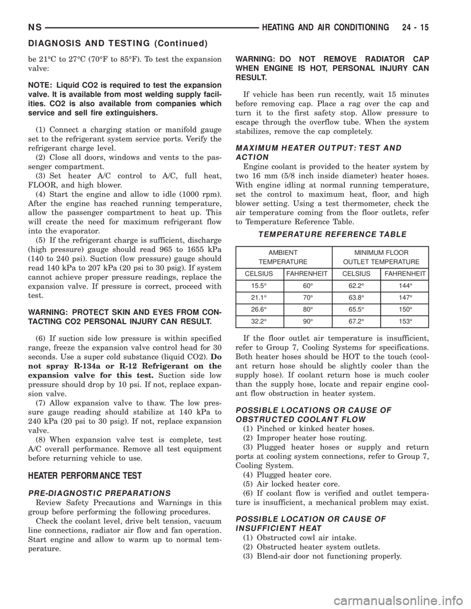
to Temperature Reference Table.
If the floor outlet air temperature is insufficient,
refer to Group 7, Cooling Systems for specifications.
Both heater hoses should be HOT to the touch (cool-
ant return hose should be slightly cooler than the
supply hose). If coolant return hose is much cooler
than the supply hose, locate and repair engine cool-
ant flow obstruction in heater system.
POSSIBLE LOCATIONS OR CAUSE OF
OBSTRUCTED COOLANT FLOW
(1) Pinched or kinked heater hoses.
(2) Improper heater hose routing.
(3) Plugged heater hoses or supply and return
ports at cooling system connections, refer to Group 7,
Cooling System.
(4) Plugged heater core.
(5) Air locked heater core.
(6) If coolant flow is verified and outlet tempera-
ture is insufficient, a mechanical problem may exist.
POSSIBLE LOCATION OR CAUSE OF
INSUFFICIENT HEAT
(1) Obstructed cowl air intake.
(2) Obstructed heater system outlets.
(3) Blend-air door not functioning properly.
TEMPERATURE REFERENCE TABLE
AMBIENT
TEMPERATUREMINIMUM FLOOR
OUTLET TEMPERATURE
CELSIUS FAHRENHEIT CELSIUS FAHRENHEIT
15.5É 60É 62.2É 144É
21.1É 70É 63.8É 147É
26.6É 80É 65.5É 150É
32.2É 90É 67.2É 153É
NSHEATING AND AIR CONDITIONING 24 - 15
DIAGNOSIS AND TESTING (Continued)
Page 1841 of 1938
CAUTION: The clutch pulley and the front plate
were mated at the factory by a burnishing opera-
tion. No attempt should be made to separately
replace either part. This will result in clutch slip-
page due to insufficient contact area.
INSTALLATION
(1) Align pin in back of field coil with hole in com-
pressor end housing, and position field coil into place.
Make sure that lead wires are properly routed, and
fasten with the wire clip screw.
(2) Install field coil retaining snap ring with snap
ring pliers. The bevel side of the snap ring facing
outward. Also both snap ring eyelets must be to the
right or left of the pin on compressor. Press snap ring
to make sure it is properly seated in the groove.
CAUTION: If snap ring is not fully seated it will
vibrate out, resulting in a clutch failure and severe
damage to the front face of the compressor.
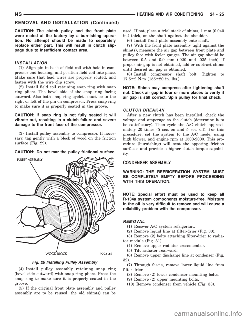
(3) Install pulley assembly to compressor. If neces-
sary, tap gently with a block of wood on the friction
surface (Fig. 29).
CAUTION: Do not mar the pulley frictional surface.
(4) Install pulley assembly retaining snap ring
(bevel side outward) with snap ring pliers. Press the
snap ring to make sure it is properly seated in the
groove.
(5) If the original front plate assembly and pulley
assembly are to be reused, the old shim(s) can beused. If not, place a trial stack of shims, 1 mm (0.040
in.) thick, on the shaft against the shoulder.
(6) Install front plate assembly onto shaft.
(7) With the front plate assembly tight against the
shim(s), measure the air gap between front plate and
pulley face with feeler gauges. The air gap should be
between 0.5 and 0.9 mm (.020 and .035 inch) If
proper air gap is not obtained, add or subtract shims
until desired air gap is obtained.
(8) Install compressor shaft bolt. Tighten to
17.562 N´m (155620 in. lbs.).
NOTE: Shims may compress after tightening shaft
nut. Check air gap in four or more places to verify if
air gap is still correct. Spin pulley for final check.
CLUTCH BREAK-IN
After a new clutch has been installed, check the
voltage and amperage to the clutch (determine it to
be satisfactory). Then cycle the A/C clutch approxi-
mately 20 times (5 sec. on and 5 sec. off). For this
procedure, set the system to the A/C mode, using
high blower, and engine rpm at 1500-2000. This pro-
cedure (burnishing) will seat the opposing friction
surfaces and provide a higher clutch torque capabil-
ity.
CONDENSER ASSEMBLY
WARNING: THE REFRIGERATION SYSTEM MUST
BE COMPLETELY EMPTY BEFORE PROCEEDING
WITH THIS OPERATION.
NOTE: Special effort must be used to keep all
R-134a system components moisture-free. Moisture
in the oil is very difficult to remove and will cause a
reliability problem with the compressor.
REMOVAL
(1) Recover A/C system refrigerant.
(2) Remove liquid line at filter-drier (Fig. 30).
(3) Remove (2) bolts attaching filter-drier to radia-
tor module (Fig. 31).
(4) Remove upper radiator crossmember.
(5) Tilt radiator rearward.
(6) Remove upper discharge line at condenser (Fig.
32).
(7) Through fascia, remove lower liquid line from
filter-drier.
(8) Remove (2) lower condenser mounting bolts.
(9) Remove (2) upper mounting bolts.
(10) Remove condenser from vehicle (Fig. 33).
Fig. 29 Installing Pulley Assembly
NSHEATING AND AIR CONDITIONING 24 - 25
REMOVAL AND INSTALLATION (Continued)
Page 1864 of 1938
NOTE: If the heater core was emptied and was not
prefilled, it is necessary to thermal cycle the vehicle
TWICE. The heater core is positioned higher than
the radiator fill cap. Therefore the heater core will
not gravity fill to level. To thermal cycle the vehicle,
it must be operated till the thermostat opens, then
turned off and allowed to cool. In order to verify
that the auxiliary unit is filled completely, the follow-
ing procedure can be used:
²Vehicle at room temperature.
²Engine is brought up to operating temperature.
²Front unit is OFF, temperature slides are at full
HEAT position.
²Engine is at idle.
²With rear blower motor ON HIGH.
²Discharge air temperature, measured at the
dual register located on the C-pillar base, is between
135É and 145É F.
REAR HEATER CORE
REMOVAL
(1) Remove the lower right quarter trim panel.
Refer to Group 23, Body.
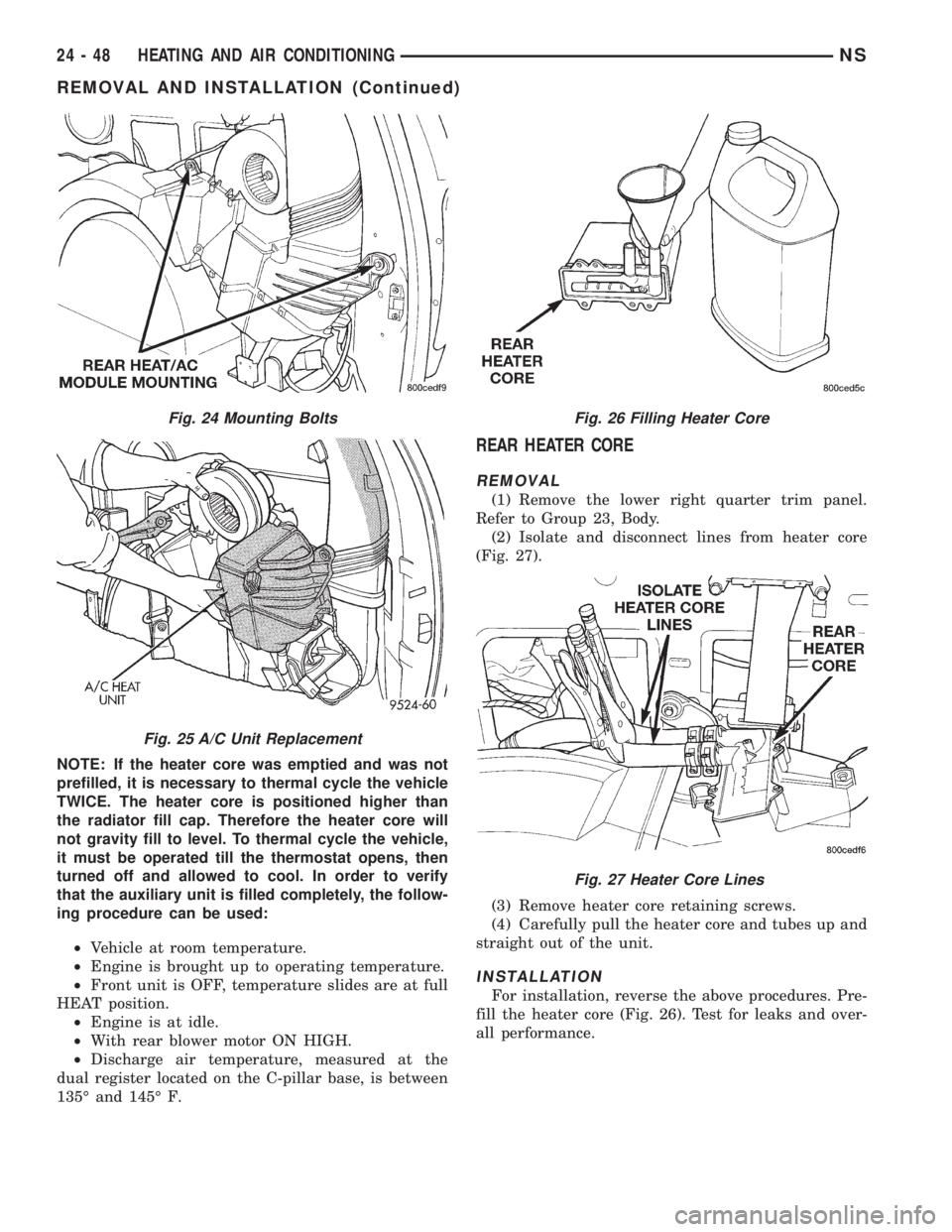
(2) Isolate and disconnect lines from heater core
(Fig. 27).
(3) Remove heater core retaining screws.
(4) Carefully pull the heater core and tubes up and
straight out of the unit.
INSTALLATION
For installation, reverse the above procedures. Pre-
fill the heater core (Fig. 26). Test for leaks and over-
all performance.
Fig. 24 Mounting Bolts
Fig. 25 A/C Unit Replacement
Fig. 26 Filling Heater Core
Fig. 27 Heater Core Lines
24 - 48 HEATING AND AIR CONDITIONINGNS
REMOVAL AND INSTALLATION (Continued)
Page 1865 of 1938

NOTE: If the heater core was emptied and was not
prefilled, it is necessary to thermal cycle the vehicle
TWICE. The heater core is positioned higher than
the radiator fill cap. Therefore the heater core will
not gravity fill to level. To thermal cycle the vehicle,
it must be operated till the thermostat opens, then
turned off and allowed to cool. In order to verify
that the auxiliary unit is filled completely, the follow-
ing procedure can be used:
²Vehicle at room temperature.
²Engine is brought up to operating temperature.
²Front unit is OFF, temperature slides are at full
HEAT position.
²Engine is at idle.
²With rear blower motor ON HIGH
²Discharge air temperature, measured at the
dual register located on the C-pillar base, is between
57ÉC to 62ÉC (135É and 145É F).
REAR HEATER LINES
REMOVAL
NOTE: Review Safety Precautions and Warnings
before proceeding with this operation.
(1) Partially drain engine cooling system. Refer to
Group 7, Engine Cooling.
(2) Loosen clamp at the front end of the hose
located at the right, outboard side of the underbody,
rearward of the front crossmember. (Fig. 2)
(3) Carefully rotate hose back and forth while tug-
ging slightly away from connector nipple. If the hose
will not come off, slice the hose at the connector nip-
ple and peel off heater hose. This method will require
heater hose replacement.
CAUTION: When removing hoses from outlet nip-
ples, do not use excessive force. Outlet nipples
may become damaged and leak engine coolant.
(4) Compress insert in rear heater hose quick con-
nection and pull downward on hose. (Fig. 4)(5) Remove (3) straps securing underbody lines.
(Fig. 1)
(6) Separate and remove rear heater lines from
vehicle.
INSTALLATION
For installation, reverse the above procedures.
MODE DOOR
REMOVAL
(1) Remove A/C unit.
(2) Place unit on bench.
(3) Remove heater core.
(4) Remove blower scroll.
(5) Remove evaporator cover.
(6) Remove A/C line to expansion valve mounting
nut.
(7) Carefully pull evaporator out of housing.
(8) Remove mode door actuator and gear exten-
sion.
(9) Remove Heater-A/C housing clips and screws.
(10) Separate housing halves.
(11) Remove mode door.
INSTALLATION
For installation, reverse the above procedures.
MODE DOOR ACTUATOR
REMOVAL
(1) Remove A/C unit.
(2) Place unit on bench.
(3) Remove mode door actuator connector.
(4) Remove mode door actuator mounting screws
and remove actuator.
INSTALLATION
For installation, reverse the above procedures.
NSHEATING AND AIR CONDITIONING 24 - 49
REMOVAL AND INSTALLATION (Continued)
Page 1880 of 1938
(6) If coil current reads zero, the coil is open and
should be replaced. If the ammeter reading is 4
amperes or more, the coil is shorted and should be
replaced. If the coil voltage is not within two volts of
the battery voltage, test clutch coil feed circuit for
excessive voltage drop.
EXPANSION VALVE
NOTE: Special effort must be used to keep all
R-134a system components moisture-free. Moisture
in the oil is very difficult to remove and will cause a
reliability problem with the compressor.
TESTS
NOTE: Expansion valve tests should be performed
after compressor tests.
Review Safety Precautions and Warnings in this
group. The work area and vehicle temperature must
be 21ÉC to 27ÉC (70ÉF to 85ÉF). To test the expansion
valve:
NOTE: Liquid CO2 is required to test the expansion
valve. It is available from most welding supply facil-
ities. CO2 is also available from companies which
service and sell fire extinguishers.
(1) Connect a charging station or manifold gauge
set to the refrigerant system service ports. Verify the
refrigerant charge level.
(2) Close all doors, windows and vents to the pas-
senger compartment.
(3) Set heater A/C control to A/C, full heat,
FLOOR, and high blower.
(4) Start the engine and allow to idle (1000 rpm).
After the engine has reached running temperature,
allow the passenger compartment to heat up. This
will create the need for maximum refrigerant flow
into the evaporator.
(5) I
f the refrigerant charge is sufficient, discharge
(high pressure) gauge should read 965 to 1655 kPa (140
to 240 psi). Suction (low pressure) gauge should read
140 kPa to 207 kPa (20 psi to 30 psig). If system cannot
achieve proper pressure readings, replace the expan-
sion valve. If pressure is correct, proceed with test.
WARNING: PROTECT SKIN AND EYES FROM CON-
TACTING CO2 PERSONAL INJURY CAN RESULT.
(6) If suction side low pressure is within specified
range, freeze the expansion valve control head for 30
seconds. Use a super cold substance (liquid CO2).Do
not spray R-134a Refrigerant on the expansion
valve for this test.Suction side low pressure should
drop by 10 psi. If not, replace expansion valve.(7) Allow expansion valve to thaw. The low pres-
sure gauge reading should stabilize at 140 kPa to
240 kPa (20 psi to 30 psig). If not, replace expansion
valve.
(8) When expansion valve test is complete, test
A/C overall performance. Remove all test equipment
before returning vehicle to use.
HEATER PERFORMANCE TEST
PRE-DIAGNOSTIC PREPARATIONS
Review Safety Precautions and Warnings in this
group before performing the following procedures.
Check the coolant level, drive belt tension, vacuum
line connections, radiator air flow and fan operation.
Start engine and allow to warm up to normal tem-
perature.
WARNING: DO NOT REMOVE RADIATOR CAP
WHEN ENGINE IS HOT, PERSONAL INJURY CAN
RESULT.
If vehicle has been run recently, wait 15 minutes
before removing cap. Place a rag over the cap and
turn it to the first safety stop. Allow pressure to
escape through the overflow tube. When the system
stabilizes, remove the cap completely.
MAXIMUM HEATER OUTPUT: TEST AND
ACTION
Engine coolant is provided to the heater system by
two 16 mm (5/8 inch inside diameter) heater hoses.
With engine idling at normal running temperature,
set the control to maximum heat, floor, and high
blower setting. Using a test thermometer, check the
air temperature coming from the floor outlets, refer
to Temperature Reference chart.
If the floor outlet air temperature is insufficient,
refer to Group 7, Cooling Systems for specifications.
Both heater hoses should be HOT to the touch (cool-
ant return hose should be slightly cooler than the
supply hose). If coolant return hose is much cooler
than the supply hose, locate and repair engine cool-
ant flow obstruction in heater system.
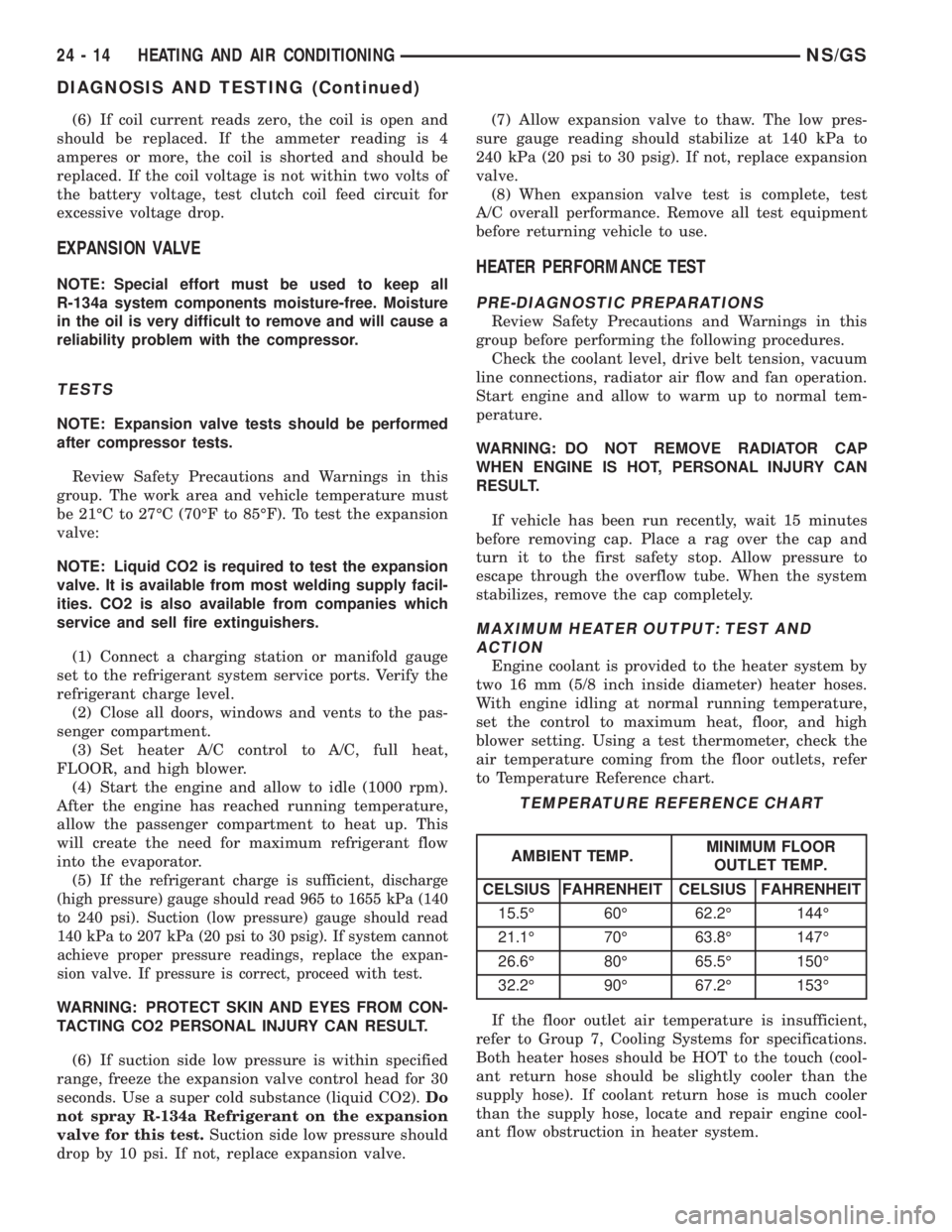
TEMPERATURE REFERENCE CHART
AMBIENT TEMP.MINIMUM FLOOR
OUTLET TEMP.
CELSIUS FAHRENHEIT CELSIUS FAHRENHEIT
15.5É 60É 62.2É 144É
21.1É 70É 63.8É 147É
26.6É 80É 65.5É 150É
32.2É 90É 67.2É 153É
24 - 14 HEATING AND AIR CONDITIONINGNS/GS
DIAGNOSIS AND TESTING (Continued)