1996 CHRYSLER VOYAGER air suspension
[x] Cancel search: air suspensionPage 1433 of 1938
VEHICLE LEADS TO THE SIDE
POWER STEERING FLUID LEAK
CONDITION POSSIBLE CAUSES CORRECTION
STEERING WHEEL DOES NOT
WANT RETURN TO CENTER
POSITION.1. Radial tire lead. 1.Rotate tires as recommended in
the Tire And Wheel Group of this
service manual.
2. Front suspension misaligned. 2. Align the front suspension as
required. Refer to the Wheel
Alignment Procedure in the
Suspension Group of this service
manual for the required wheel
alignment procedure.
3. Wheel braking. 3. Check for dragging brakes. Refer
to the procedures in the Brake
Group of this service manual.
4. Unbalanced steering gear valve.
(If this is the cause, the steering
efforts will be very light in direction
of lead and heavier in the opposite
direction.4. Replace steering gear.
STEERING WHEEL HAS FORE
AND AFT LOOSENESS.1. Steering wheel to steering column
shaft retaining nut not properly
tightened and torqued.1. Tighten the retaining nut to its
specified torque specification.
2. Steering column lower bearing
spring retainer slipped on steering
column shaft.2. Replace steering column.
3. Loose steering column to
instrument panel mounting nuts.3. Verify that the 4 mounting nuts for
the steering column are tightened to
the specified torque.
4. Binding intermediate steering
shaft coupler.4. Disconnect intermediate steering
coupler and see if looseness no
longer exists. If yes replace
intermendiate steering coupler.
CONDITION POSSIBLE CAUSES CORRECTION
LOW FLUID LEVEL WITH: NO
VISIBLE SIGNS OF A LEAK ON
THE STEERING GEAR, POWER
STEERING PUMP, FLOOR OR
ANYWHERE ELSE.1. Overfilled power steering pump
fluid reservoir.1. Adjust the power steering fluid fill
to the correct level.
LOW FLUID LEVEL WITH:
VISIBLE LEAK ON STEERING
GEAR, POWER STEERING
PUMP, FLOOR OR ANYWHERE
ELSE.2. Power steering hose connections
at the power steering pump or
steering gear.2. Check for loose fittings and if
found, tighten the fitting to its
specified torque. If fittings are tight
examine the fittings for damaged or
missing O-ring seals and replace as
required.
3. Power steering pump or power
steering gear leaking.3. Identify the location of the leak
and repair or replace the component
as required. Refer to Power Steering
Pump and/or Power Steering Gear in
this group of the service manual for
required procedures.
NSSTEERING 19 - 7
DIAGNOSIS AND TESTING (Continued)
Page 1439 of 1938
(18) Remove the 3 previously loosened bolts
attaching the front bracket to the power steering
pump and separate the power steering pump from
the front bracket prior to removing the pump from
the vehicle.
(19) The power steering pump is removed from the
vehicle by pulling it out through the exhaust tunnel
area in the floor pan of the vehicle.
INSTALL
(1) Install power steering pump back in vehicle
using the reverse order of its removal through the
exhaust tunnel are of the vehicle.
(2) Install the power steering pump on its cast
mounting bracket and loosely install nut to hold
pump in place (Fig. 9).
(3) Install the front bracket on the power steering
pump and loosely install the 3 mounting bolts (Fig.
10). Then install the nut and bolt attaching the front
bracket to the cast bracket (Fig. 10).
(4) Tighten the 3 power steering pump mounting
bolts (Fig. 10) to a torque of 54 N´m (40 ft. lbs.).
NOTE: Before installing power steering fluid pres-
sure hose on power steering pump, inspect the
O-ring on the pressure hose for damage and
replace if necessary.
(5) Install the power steering fluid pressure line
onto the output fitting of the power steering pump
(Fig. 8). Tighten the pressure line to pump fitting
tube nut to a torque of 31 N´m (275 in. lbs.).
(6) Install the power steering fluid, low pressure
return hose on the power steering pump low pressure
fitting (Fig. 8).Be sure hose clamps are properly
reinstalled.
(7) Install the power steering fluid supply hose
from the power steering fluid reservoir, on the power
steering pump fluid fitting (Fig. 7).Be sure hose is
clear of accessory drive belts all hose clamps
are properly reinstalled.
(8) Install the power steering pump drive belt on
pulley. See Cooling, Group 7 for detailed installation
procedure.
(9) Install the accessory drive splash shield (Fig.
6).
(10) Install the power steering fluid return hose on
the steel tube at the front suspension cradle (Fig. 5).
(11) Install a screw type hose clamp on the power
steering hose to steel tube connection.Be sure hose
clamps are properly reinstalled.Tighten the screw
clamp to a torque of 2 N´m (18 in. lbs.).
CAUTION: The protective heat shield sleeves must
cover the entire rubber hose and hose to tube con-
nection portion of both the power steering fluid
pressure and return hoses (Fig. 5). This is requiredto prevent the overheating of the power steering
hoses.
(12) When used, properly position the protective
heat sleeves on the power steering hoses (Fig. 5).
Then, tie strap the heat sleeves to the power steering
hoses to keep them in their proper position.
(13) Install the exhaust pipe on the exhaust man-
ifold. Install all exhaust system hangers/isolators on
the exhaust system brackets.
(14) Connect the oxygen sensor wiring harness to
the vehicle wiring harness. Install wiring harness
grommet in the floor pan of the vehicle.
(15) Lower vehicle.
(16) Adjust the power steering pump drive belt.
See Cooling, Group 7 for detailed adjustment proce-
dure.
(17) Tighten the top nut and bottom bolt on the
power steering pump front mounting bracket (Fig. 3)
to a torque of 54 N´m (40 ft. lbs.).
CAUTION: Do not use automatic transmission fluid
in power steering system. Only use MoparT, Power
Steering Fluid, or equivalent.
(18) Fill the remote power steering pump fluid res-
ervoir to correct fluid level.
(19) Install cap on power steering fluid reservoir.
(20) Connect the negative battery cable on the
negative battery post.
(21) Start engine and turn steering wheel several
times from stop to stop to bleed air from fluid in sys-
tem. Stop engine, check fluid level, and inspect sys-
tem for leaks. See Checking Fluid Level.
3.0 LITER POWER STEERING PUMP
REMOVE
WARNING: POWER STEERING OIL, ENGINE COM-
PONENTS AND THE EXHAUST SYSTEM MAY BE
EXTREMELY HOT IF ENGINE HAS BEEN RUNNING.
DO NOT START ENGINE WITH ANY LOOSE OR DIS-
CONNECTED HOSES. DO NOT ALLOW HOSES TO
TOUCH HOT EXHAUST MANIFOLD OR CATALYST.
(1) Remove the (-) negative battery cable from the
battery and isolate cable.
(2) Remove cap from power steering fluid reser-
voir.
(3) Using a siphon pump, remove as much power
steering fluid as possible from the power steering
fluid reservoir.
NSSTEERING 19 - 13
REMOVAL AND INSTALLATION (Continued)
Page 1442 of 1938
(15) Fill the remote power steering pump fluid res-
ervoir to correct fluid level.
(16) Install cap on power steering fluid reservoir.
(17) Connect the negative battery cable on the
negative battery post.
(18) Start engine and turn steering wheel several
times from stop to stop to bleed air from fluid in sys-
tem. Stop engine, check fluid level, and inspect sys-
tem for leaks. See Checking Fluid Level.
3.3/3.8 LITER POWER STEERING PUMP
REMOVE
WARNING: POWER STEERING OIL, ENGINE COM-
PONENTS AND THE EXHAUST SYSTEM MAY BE
EXTREMELY HOT IF ENGINE HAS BEEN RUNNING.
DO NOT START ENGINE WITH ANY LOOSE OR DIS-
CONNECTED HOSES. DO NOT ALLOW HOSES TO
TOUCH HOT EXHAUST MANIFOLD OR CATALYST.
(1) Remove the (-) negative battery cable from the
battery and isolate cable.
(2) Remove cap from power steering fluid reser-
voir.
(3) Using a siphon pump, remove as much power
steering fluid as possible from the power steering
fluid reservoir.
(4) Raise vehicle on jack stands or centered on a
frame contact type hoist. See Hoisting, in the Lubri-
cation and Maintenance section of this service man-
ual for the required lifting procedure.
(5) Disconnect the oxygen sensor wiring harness
from the vehicle wiring harness. Access to connection
at vehicle wiring harness is through the oxygen sen-
sor wiring harness grommet in the floor pan of the
vehicle.
NOTE: The exhaust system needs to be removed
from the engine to allow for an area to remove the
power steering pump from the vehicle.
(6) Remove the catalytic converter from the
exhaust manifold. Then remove all the exhaust sys-
tem hangers/isolators from the brackets on the
exhaust system.
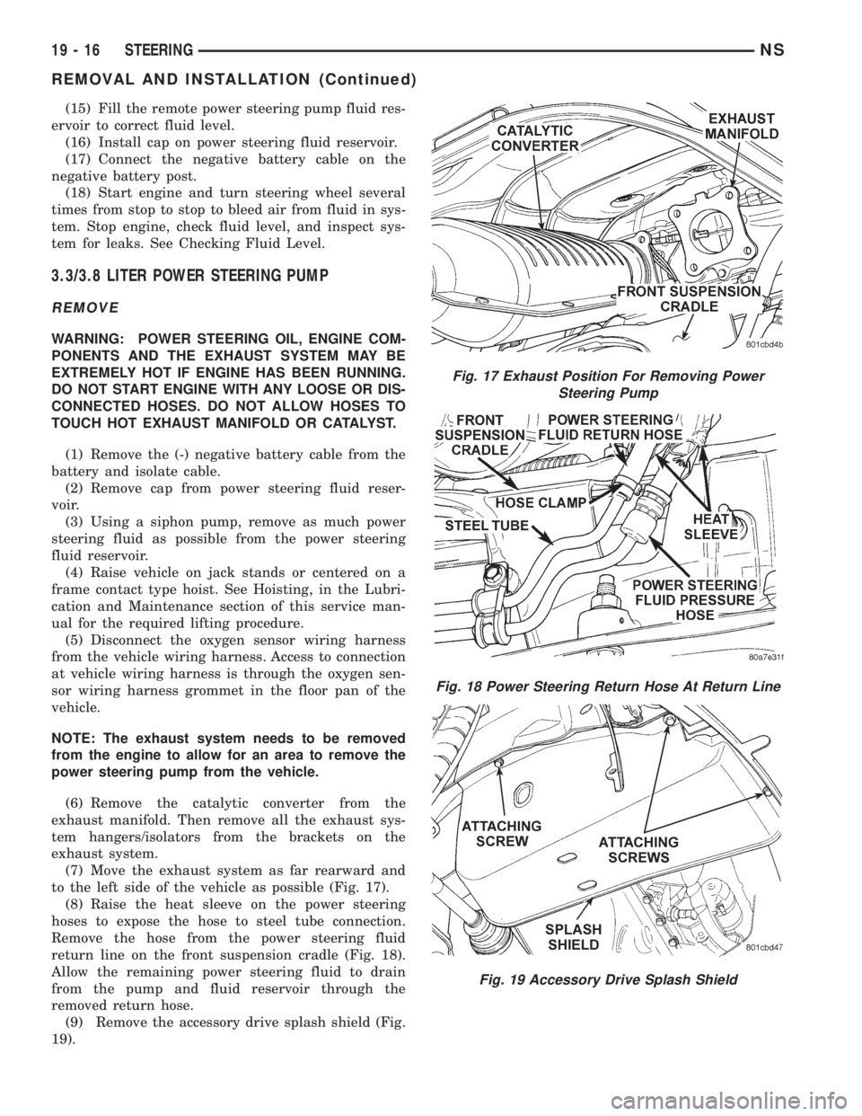
(7) Move the exhaust system as far rearward and
to the left side of the vehicle as possible (Fig. 17).
(8) Raise the heat sleeve on the power steering
hoses to expose the hose to steel tube connection.
Remove the hose from the power steering fluid
return line on the front suspension cradle (Fig. 18).
Allow the remaining power steering fluid to drain
from the pump and fluid reservoir through the
removed return hose.
(9) Remove the accessory drive splash shield (Fig.
19).
Fig. 17 Exhaust Position For Removing Power
Steering Pump
Fig. 18 Power Steering Return Hose At Return Line
Fig. 19 Accessory Drive Splash Shield
19 - 16 STEERINGNS
REMOVAL AND INSTALLATION (Continued)
Page 1444 of 1938
NOTE: Before installing power steering pressure
hose on power steering pump, inspect the O-ring
on the power steering pressure hose for damage
and replace if required.
(4) Install the power steering fluid pressure line
onto the output fitting of the power steering pump
(Fig. 21). Tighten the pressure line to pump fitting
tube nut to a torque of 31 N´m (275 in. lbs.).
(5) Install the power steering fluid, low pressure
return hose on the power steering pump low pressure
fitting (Fig. 21).Be sure hose clamps are prop-
erly reinstalled.
(6) Install the power steering fluid supply hose
from the power steering fluid reservoir, on the power
steering pump fluid fitting (Fig. 21).Be sure hose is
clear of accessory drive belts and all hose
clamps are properly reinstalled.
(7) Install the serpentine drive belt (Fig. 20). See
Cooling, Group 7 for detailed installation procedure.
(8) Install the power steering fluid return hose on
the steel tube at the front suspension cradle (Fig.
18).
(9) Install a screw type hose clamp on the power
steering hose to steel tube connection.Be sure hose
clamps are properly reinstalled.Tighten the screw
clamp to a torque of 2 N´m (18 in. lbs.).
CAUTION: The protective heat shield sleeves must
cover the entire rubber hose and hose to tube con-
nection portion of both the power steering fluid
pressure and return hoses (Fig. 18). This is required
to keep the power steering hoses from becoming
overheated.
(10) When used, properly position the protective
heat sleeves on the power steering hoses (Fig. 18).
Then, tie strap the heat sleeves to the power steering
hoses to keep them in their proper position.
(11) Install the exhaust pipe on the exhaust man-
ifold. Install all exhaust system hangers/isolators on
the exhaust system brackets.
(12) Connect the oxygen sensor wiring harness to
the vehicle wiring harness. Install wiring harness
grommet in the floor pan of the vehicle.
(13) Install the accessory drive splash shield (Fig.
19).
(14) Lower vehicle.
CAUTION: Do not use automatic transmission fluid
in power steering system. Only use MoparT, Power
Steering Fluid, or equivalent.
(15) Fill the remote power steering pump fluid res-
ervoir to correct fluid level.
(16) Install cap on power steering fluid reservoir.(17) Connect the negative battery cable on the
negative battery post.
(18) Start engine and turn steering wheel several
times from stop to stop to bleed air from fluid in sys-
tem. Stop engine, check fluid level, and inspect sys-
tem for leaks. See Checking Fluid Level.
POWER STEERING FLUID RESERVOIR TO PUMP
SUPPLY HOSE
REMOVE
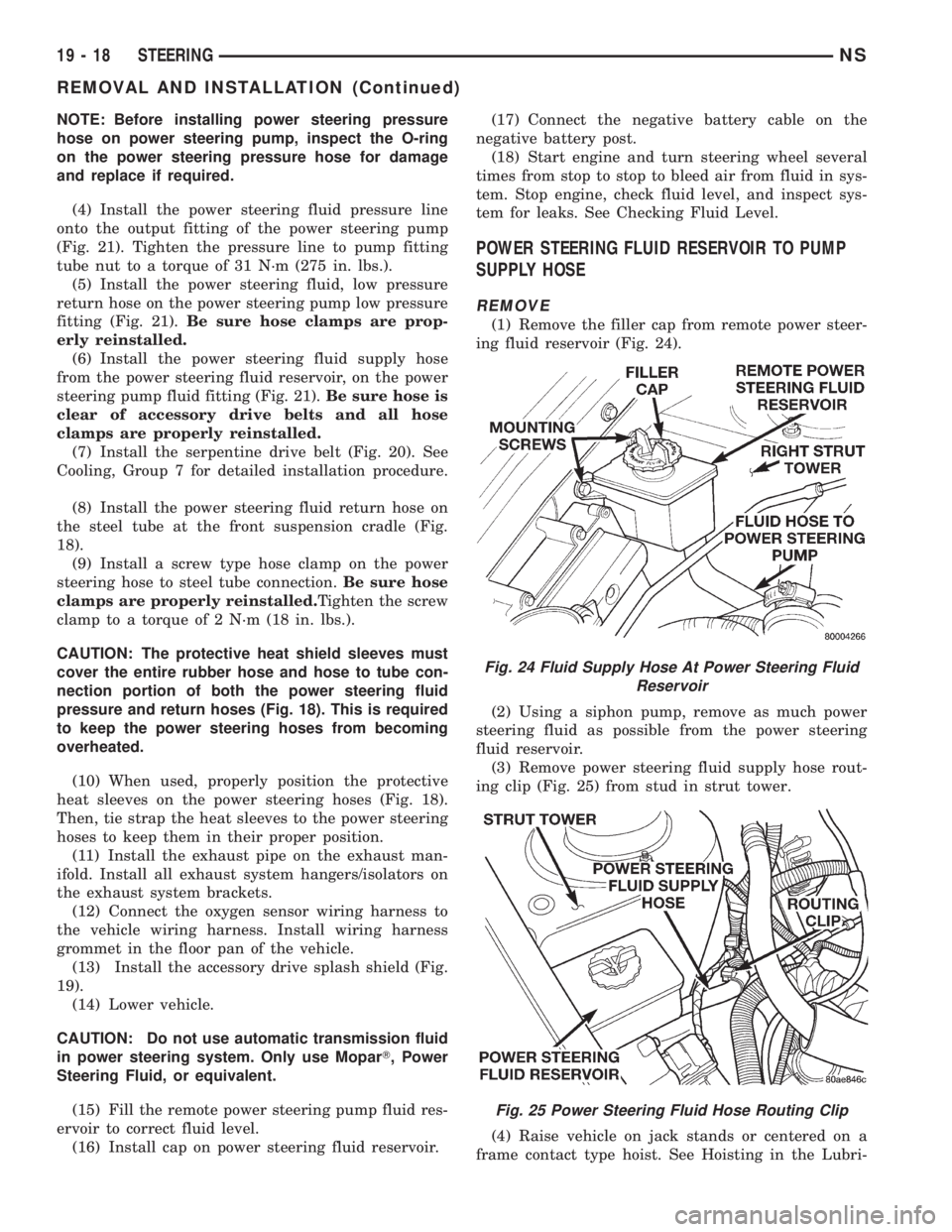
(1) Remove the filler cap from remote power steer-
ing fluid reservoir (Fig. 24).
(2) Using a siphon pump, remove as much power
steering fluid as possible from the power steering
fluid reservoir.
(3) Remove power steering fluid supply hose rout-
ing clip (Fig. 25) from stud in strut tower.
(4) Raise vehicle on jack stands or centered on a
frame contact type hoist. See Hoisting in the Lubri-
Fig. 24 Fluid Supply Hose At Power Steering Fluid
Reservoir
Fig. 25 Power Steering Fluid Hose Routing Clip
19 - 18 STEERINGNS
REMOVAL AND INSTALLATION (Continued)
Page 1450 of 1938

(6) Remove the pressure fitting/flow control valve
from the power steering pump and remove and dis-
card the O-Ring seal.
ASSEMBLE
(1) Install a new O-Ring seal on the pressure fit-
ting/flow control valve, and wet the O-Ring with
clean fresh power steering fluid.
(2) Install the pressure fitting/flow control valve in
the power steering pump. Tighten the pressure fit-
ting/flow control valve to a torque of 75 N´m (55 ft.
lbs.).
CAUTION: When tightening and torquing the pres-
sure hose at the power steering pump, the hose
should be rotated against the fluid return hose fit-
ting on the pump.(3) Install the power steering fluid pressure hose
in the pressure fitting/flow control valve (Fig. 37).
Tighten the tube nut to a torque of 34 N´m (25 ft.
lbs.)
(4) Install the power steering fluid return hose on
the steel tube at the front suspension cradle (Fig.
36).
(5) Install a screw type hose clamp on the power
steering hose to steel tube connection. Tighten the
screw clamp to a torque of 2 N´m (18 in. lbs.).
CAUTION: The protective heat shield sleeves must
cover the entire rubber hose and hose to tube con-
nection portion of both the power steering fluid
pressure and return hoses (Fig. 36). This is required
to keep the power steering hoses from becoming
overheated.
(6) When used, properly position the protective
heat sleeves (Fig. 36) on the power steering hoses.
Then, tie strap the heat sleeves to the power steering
hoses to keep them in their proper position.
(7) Fill the power steering system with fluid, bleed
air from system and check that power steering fluid
is at correct level.
SPECIFICATIONS
POWER STEERING SYSTEM SPECIFICATIONS
Flow At 1500 RPM And Minimum Pressure.5.0 to 7.0
Liters/Min (1.3 to 1.9 GPM)
Control Valve Pressure Relief. 9653 to 10342 kPa (1400
to 1500psi)
POWER STEERING PUMP FASTENER TORQUE
SPECIFICATIONS
DESCRIPTION TORQUE
POWER STEERING PUMP:
Flow Control Valve Fitting. . . .75 N´m (55 ft. lbs.)
Mounting Bolts.............54N´m(40ft.lbs.)
Rear Bracket To Engine
Mounting Bolts.............54N´m(40ft.lbs.)
POWER STEERING FLUID HOSES:
Hose Tube Nuts.............34N´m(25ft.lbs.)
Routing Bracket To
Suspension Cradle..........28N´m(21ft.lbs.)
Fig. 36 Return Hose At Steel Tube
Fig. 37 Pressure Hose Connection To Power
Steering Pump
19 - 24 STEERINGNS
DISASSEMBLY AND ASSEMBLY (Continued)
Page 1494 of 1938
(5) Continuity should exist only with transaxle in
Reverse position.
(6) No continuity should exist from either pin to
the case.
TRANSAXLE AND TORQUE CONVERTER REMOVAL
NOTE: Transaxle removal does NOT require engine
removal.
The transaxle and torque converter must be
removed as an assembly; otherwise, the torque con-
verter drive plate, pump bushing, or oil seal may be
damaged. The drive plate will not support a load;
therefore, none of the weight of the transaxle should
be allowed to rest on the plate during removal.
REMOVAL
(1) Disconnect negative battery cable.
(2) Remove air cleaner and hoses.
(3) Disconnect throttle linkage and shift linkage
from transaxle.
(4) Unplug torque converter clutch connector,
located near the dipstick. Unplug the gear position
switch.
(5) Remove transaxle dipstick tube.
(6) Remove the transaxle cooler lines and plug.
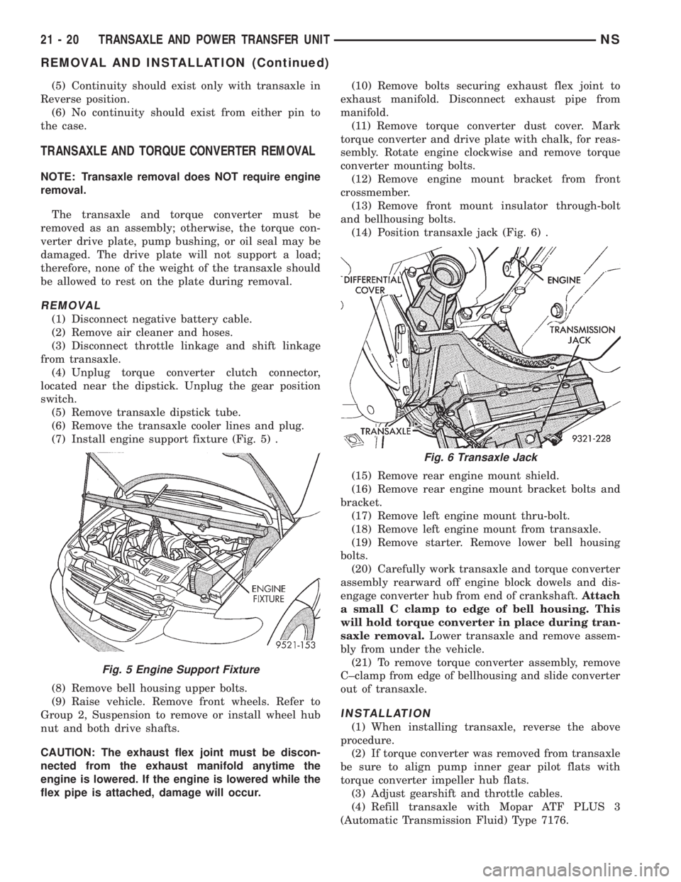
(7) Install engine support fixture (Fig. 5) .
(8) Remove bell housing upper bolts.
(9) Raise vehicle. Remove front wheels. Refer to
Group 2, Suspension to remove or install wheel hub
nut and both drive shafts.
CAUTION: The exhaust flex joint must be discon-
nected from the exhaust manifold anytime the
engine is lowered. If the engine is lowered while the
flex pipe is attached, damage will occur.(10) Remove bolts securing exhaust flex joint to
exhaust manifold. Disconnect exhaust pipe from
manifold.
(11) Remove torque converter dust cover. Mark
torque converter and drive plate with chalk, for reas-
sembly. Rotate engine clockwise and remove torque
converter mounting bolts.
(12) Remove engine mount bracket from front
crossmember.
(13) Remove front mount insulator through-bolt
and bellhousing bolts.
(14) Position transaxle jack (Fig. 6) .
(15) Remove rear engine mount shield.
(16) Remove rear engine mount bracket bolts and
bracket.
(17) Remove left engine mount thru-bolt.
(18) Remove left engine mount from transaxle.
(19) Remove starter. Remove lower bell housing
bolts.
(20) Carefully work transaxle and torque converter
assembly rearward off engine block dowels and dis-
engage converter hub from end of crankshaft.Attach
a small C clamp to edge of bell housing. This
will hold torque converter in place during tran-
saxle removal.Lower transaxle and remove assem-
bly from under the vehicle.
(21) To remove torque converter assembly, remove
C±clamp from edge of bellhousing and slide converter
out of transaxle.
INSTALLATION
(1) When installing transaxle, reverse the above
procedure.
(2) If torque converter was removed from transaxle
be sure to align pump inner gear pilot flats with
torque converter impeller hub flats.
(3) Adjust gearshift and throttle cables.
(4) Refill transaxle with Mopar ATF PLUS 3
(Automatic Transmission Fluid) Type 7176.
Fig. 5 Engine Support Fixture
Fig. 6 Transaxle Jack
21 - 20 TRANSAXLE AND POWER TRANSFER UNITNS
REMOVAL AND INSTALLATION (Continued)
Page 1721 of 1938
Improper inflation can cause:
²Uneven wear patterns
²Reduced tread life
²Reduced fuel economy
²Unsatisfactory ride
²The vehicle to drift.
Proper tire air inflation pressure specifications can
be found on the Vehicle Tire Placard provided with
the vehicle. See owner's manual.
Tire pressures have been chosen to provide safe
operation, vehicle stability, and a smooth ride. Tire
pressure should be checked cold once per month.
Check tire pressure more frequently when the
weather temperature varies widely. Tire pressure will
decrease when the outdoor temperature drops.
Tire inflation pressures specified on the placard
are always cold inflation pressure. Cold inflation
pressure is obtained after the vehicle has not been
operated for at least 3 hours, or the vehicle is driven
less than one mile after being inoperative for 3
hours. Tire inflation pressures may increase from 2
to 6 pounds per square inch (psi) during operation.
Do not reduce this normal pressure build-up.
TIRE PRESSURE FOR HIGH-SPEED DRIVING
Chrysler Corporation advocates driving at safe
speeds within posted speed limits. Where speed lim-
its allow the vehicle to be driven at high speeds, cor-
rect tire inflation pressure is very important. For
speeds up to and including 75 mph (120 km/h), tires
must be inflated to the pressures shown on the tire
placard.
Vehicles loaded to the maximum capacity should
not be driven at speeds above 75 mph (120 km/h).
For emergency vehicles that are driven at speeds
over 90 mph (144 km/h), special high-speed tires
must be used. Consult tire manufacturer for correct
inflation pressure recommendations.
REPLACEMENT TIRES
The original equipment tires provide a proper bal-
ance of many characteristics such as:
²Ride
²Noise
²Handling
²Durability
²Tread life
²Traction
²Rolling resistance
²Speed capability
It is recommend that tires equivalent to the origi-
nal equipment tires be used when replacement is
needed.
Failure to use equivalent replacement tires may
adversely affect the safety and handling of the vehicle.
The use of oversize tires not listed in the specifica-
tion charts may cause interference with vehicle com-
ponents. Under extremes of suspension and steering
travel, interference with vehicle components may
cause tire damage.
WARNING: FAILURE TO EQUIP THE VEHICLE WITH
TIRES HAVING ADEQUATE SPEED CAPABILITY
CAN RESULT IN SUDDEN TIRE FAILURE.
DIAGNOSIS AND TESTING
PRESSURE GAUGES
A quality air pressure gauge is recommended to
check tire pressure. After checking the air pressure,
replace valve cap finger tight.
TREAD WEAR INDICATORS
Tread wear indicators are molded into the bottom
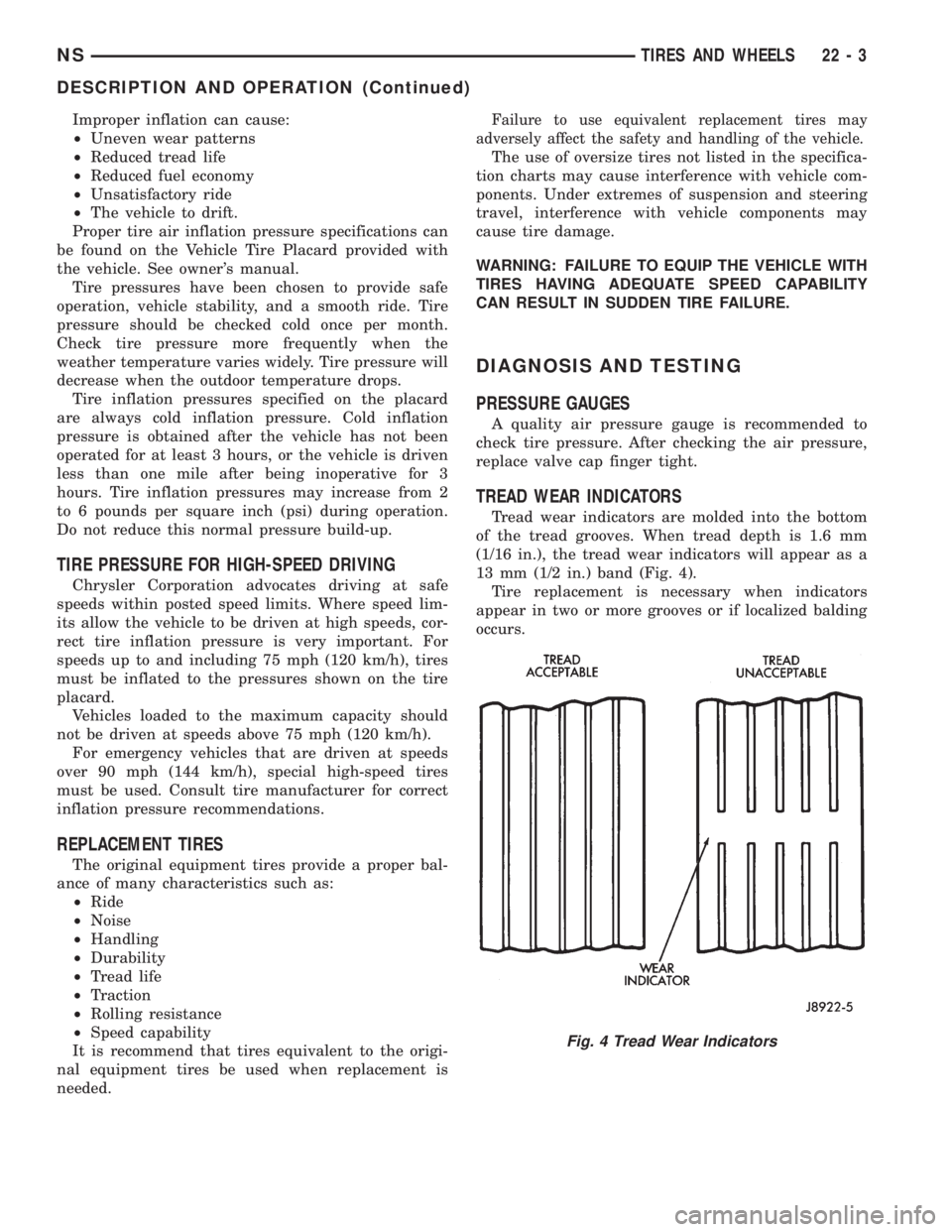
of the tread grooves. When tread depth is 1.6 mm
(1/16 in.), the tread wear indicators will appear as a
13 mm (1/2 in.) band (Fig. 4).
Tire replacement is necessary when indicators
appear in two or more grooves or if localized balding
occurs.
Fig. 4 Tread Wear Indicators
NSTIRES AND WHEELS 22 - 3
DESCRIPTION AND OPERATION (Continued)