1996 CHRYSLER VOYAGER wipers
[x] Cancel search: wipersPage 828 of 1938

C57
30A
FUSE
19
BATT A0
POWER
DISTRIBUTION
CENTER
85
3086
87A
87
87A
8630
8587 WIPER
ON
RELAYLOW HIGH/
WIPER
RELAY
C42 5C5C54C53
31
WIPER
MODULE
2
V4
12
RD/YLV3
12
BR/WT
4
12
G300
Z1
14
BK
DG/WT20 V7
BK18Z1
0
1
FRONT
WIPER
SWITCH
6
5
3
WT20 V16
P18 B23
B1
V16
20
WT
41C17C2 C173
V52
20
DG/YL
V14
18
RD/VT
WIPER
ON/OFF
RELAY
CONTROLFRONT
WIPER
SWITCHWIPER
PARK
SWITCH
SENSE
MODULE CONTROL
BODY
10
1 0
21
0 OFF
1 HIGH
3 WASH 2 LOW
7
7PTC9A
RUN-ACC A31
BLOCK JUNCTION
5C3
F1
20
DB
SWITCH) FUNCTION
MULTI-
(PART OF
118
MUX
M
(8W-10-19)(8W-10-8)
(8W-10-8)
(8W-15-5)
(8W-15-7)
(8W-45-3)
(8W-45-4) (8W-12-16)(8W-12-2)(8W-10-16)
8W - 53 - 2 8W-53 WIPERSNS/GS
J988W-3GS005302
Page 829 of 1938

BK/TN20 G29
SIGNALFLUID WASHERLOW
58C1LOW
WASHER
FLUID
SWITCH
A
B
14
G301
Z1
20
BK
21 0
DB20F1
A
MOTOR WASHER
REAR
FRONT
WASHER
MOTOR
DB20F1
BR20 V10
BK18Z1
G200
13
B A
POWER
DISTRIBUTION
CENTER
RELAY LOW
HIGH/
WIPER
10
G300
C57
30A
FUSE
19
BATT A0
85
3086
87A
8786
85 WIPER
ON
RELAY
C425C5
BK18Z1
0
1
FRONT
WIPER
SWITCH
5
3
WT20 V16
P18 B231
V16
20
WT
C173
V14
18
RD/VT
WIPER
ON/OFF
RELAY
CONTROL
JUNCTION
BLOCK
BODY
CONTROL
MODULE8
11
20
18C3C221
V10
20
BR
CONTROLMOTOR WASHERFRONT
JUNCTION
BLOCK
RUN-ACC A31
PTC
7
9A
3C2
30
B1
0 OFF
1 HIGH
2 LOW
3 WASH
SWITCH) FUNCTION
MULTI-
(PART OF
7
6
WASHER
MODULE
(BUILT-
UP-EXPORT)
8787A
31
FUSED
IGNITION
(RUN-ACC)
M
(8W-15-11)(8W-53-4)
(8W-15-4)(8W-10-8)
(8W-53-2)
(8W-15-7)(8W-10-19)(8W-10-8)
(8W-12-2)
(8W-45-3)
(8W-45-4)(8W-12-2) (8W-10-16)
(8W-12-16)
(8W-53-5)
NS/GS8W-53 WIPERS 8W - 53 - 3
GS005303J988W-3
Page 830 of 1938

BK/LG18Z2
G200
5
C121
INDICATOR REAR
WIPER
DELAY
ON INDICATOR ON
WIPER
REAR
DELAY WIPER
REAR
SWITCH SWITCH REAR
WIPER
ON SWITCH WASHER
REARDRIVER INDICATORON DELAY WIPER
ON
INDICATOR
DRIVER SWITCHDELAYWIPERREAR REAR
WIPER
ON
SWITCH SENSE SWITCH WASHERREAR
MUX WASHWIPE/ REAR
YL/WT22 V26
C12
HVAC
CONTROL
BK18Z1
6
G400
L16 J03A
32
78B17
LJ01
BR/LG18 V13BR/PK18 V23
2
REAR
WIPER
MOTOR
M
1
3
49C1
REAR
WIPER
MOTOR
DRIVER
BK/WT20 V20
C238REAR
MUX WASHWIPE/
CONTROLMOTOR WASHERREAR
C150
7C1
(ST-RUN)IGN. FUSED
1211
6FUSE20A
ST-RUN A21
MODULE
CONTROL
BODY
C23
9A
7
PTC
RUN-ACC A31
BLOCK
JUNCTION
A
BF1
20
DB
MOTOR WASHER
REARFRONT
WASHER
MOTOR
A
F1
20
DB
CONTROL HEATER
A/C
13
FUSED
IGNITION
(RUN-ACC)PUMP
M
(8W-15-4)(8W-42-3)
(8W-15-14) (8W-12-9)(8W-10-16)
(8W-45-2)
(8W-45-4)
(8W-45-6) (8W-12-16)(8W-10-16)
(8W-12-2)
(8W-53-3)
(8W-42-3)
8W - 53 - 4 8W-53 WIPERSNS/GS
J988W-3GS005304
Page 831 of 1938

BLOCK JUNCTION
22FUSE40A
BATT A0
CENTER
DISTRIBUTION
POWER30
87
PARK
LAMP
RELAY
4C1
2C1
L7
12
BK/YL
RUN-ACC A31BATT A2
9A PTC
73PTC
9A15A
FUSE
5
LOGIC
20
BODY
CONTROL
MODULE
18C321C234C1
11
V10
20
BR
BR20 V10
MOTOR WASHER
FRONT
BV53
18
RD/YL
WASHER HEADLAMP
WASHER
MODULE
B
A11
Z1
18
BK
SWITCH) FUNCTION
MULTI-
(PART OF
SWITCH
WIPER
FRONT
G301
3130
S56P
FRONT
WASHER
MOTOR
CONTROLWASHER
PUMP
CONTROL
SWITCH
OUTPUTM
(8W-12-2) (8W-10-17)(8W-10-8)
(8W-10-8)
(8W-50-11)
(8W-10-16) (8W-10-13)
(8W-12-16) (8W-12-15)(8W-12-8)
(8W-45-4)
(8W-53-3)
(8W-53-3)(8W-15-10)
NS/GS8W-53 WIPERS
BUILT-UP-EXPORT8W - 53 - 5
GS005305J988W-3
Page 1152 of 1938

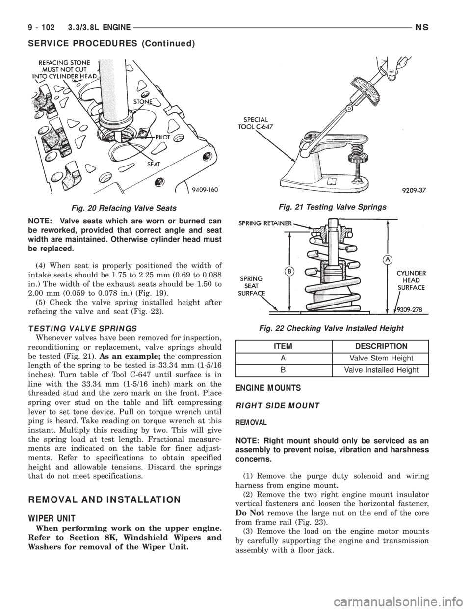
NOTE: Valve seats which are worn or burned can
be reworked, provided that correct angle and seat
width are maintained. Otherwise cylinder head must
be replaced.
(4) When seat is properly positioned the width of
intake seats should be 1.75 to 2.25 mm (0.69 to 0.088
in.) The width of the exhaust seats should be 1.50 to
2.00 mm (0.059 to 0.078 in.) (Fig. 19).
(5) Check the valve spring installed height after
refacing the valve and seat (Fig. 22).
TESTING VALVE SPRINGS
Whenever valves have been removed for inspection,
reconditioning or replacement, valve springs should
be tested (Fig. 21).As an example;the compression
length of the spring to be tested is 33.34 mm (1-5/16
inches). Turn table of Tool C-647 until surface is in
line with the 33.34 mm (1-5/16 inch) mark on the
threaded stud and the zero mark on the front. Place
spring over stud on the table and lift compressing
lever to set tone device. Pull on torque wrench until
ping is heard. Take reading on torque wrench at this
instant. Multiply this reading by two. This will give
the spring load at test length. Fractional measure-
ments are indicated on the table for finer adjust-
ments. Refer to specifications to obtain specified
height and allowable tensions. Discard the springs
that do not meet specifications.
REMOVAL AND INSTALLATION
WIPER UNIT
When performing work on the upper engine.
Refer to Section 8K, Windshield Wipers and
Washers for removal of the Wiper Unit.
ENGINE MOUNTS
RIGHT SIDE MOUNT
REMOVAL
NOTE: Right mount should only be serviced as an
assembly to prevent noise, vibration and harshness
concerns.
(1) Remove the purge duty solenoid and wiring
harness from engine mount.
(2) Remove the two right engine mount insulator
vertical fasteners and loosen the horizontal fastener,
Do Notremove the large nut on the end of the core
from frame rail (Fig. 23).
(3) Remove the load on the engine motor mounts
by carefully supporting the engine and transmission
assembly with a floor jack.
Fig. 20 Refacing Valve SeatsFig. 21 Testing Valve Springs
Fig. 22 Checking Valve Installed Height
ITEM DESCRIPTION
A Valve Stem Height
B Valve Installed Height
9 - 102 3.3/3.8L ENGINENS
SERVICE PROCEDURES (Continued)
Page 1157 of 1938

(4) Remove upper intake manifold. Refer to Group
11, Exhaust System and Intake Manifolds for proce-
dure.
(5) Remove cylinder head covers and spark plugs.
(6) Remove electrical connector from ignition coils.
(7) Using suitable socket and flex handle at crank-
shaft pulley retaining screw, turn engine so the num-
ber 1 piston is at Top Dead Center on the
compression stroke.
(8) Remove rocker arms with rocker shaft and
install a dummy shaft. The rocker arms should not
be disturbed and left on shaft.
(9) With air hose attached to spark plug adapter
installed in number 1 spark plug hole, apply 90 to
100 psi air pressure (620.5 to 689 kPa). This is to
hold valves in place while servicing components.
(10) Using Tool C-4682 or equivalent, compress
valve spring and remove retainer valve locks and
valve spring.
(11) The intake valve stem seals should be pushed
firmly and squarely over the valve guide using the
valve stem as guide.Do Not Forceseal against top
of guide. When installing the valve retainer locks,
compress the springonly enoughto install the
locks.
CAUTION: Do not pinch seal between retainer and
top of valve guide.
(12) Follow the same procedure on the remaining 5
cylinders using the firing sequence 1-2-3-4-5-6.Make
sure piston in cylinder is at TDC on the valve
spring that is being covered.
(13) Remove spark plug adapter tool.
(14) Remove dummy shaft and install rocker shaft
assembly and tighten screws to 28 N´m (250 in. lbs.).
(15) Install cylinder head covers tighten screws to
14 N´m (120 in. lbs.) and electrical connector to igni-
tion coils.
(16) Install Intake Manifold. Refer to Group 11,
Exhaust System and Intake Manifold for procedure.
(17) Connect negative cable to battery.
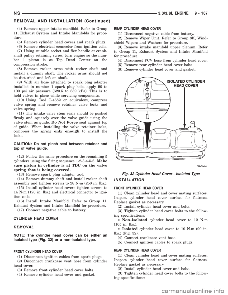
CYLINDER HEAD COVER
REMOVAL
NOTE: The cylinder head cover can be either an
isolated type (Fig. 32) or a non-isolated type.
FRONT CYLINDER HEAD COVER
(1) Disconnect ignition cables from spark plugs.
(2) Disconnect crankcase vent hose from cylinder
head cover.
(3) Remove front cylinder head cover bolts.
(4) Remove cylinder head cover and gasket.REAR CYLINDER HEAD COVER
(1) Disconnect negative cable from battery.
(2) Remove Wiper Unit. Refer to Group 8K, Wind-
shield Wipers and Washers for procedure.
(3) Remove intake manifold upper plenum. Refer
to Group 11, Exhaust System and Intake Manifold
for procedure.
(4) Disconnect PCV hose from cylinder head cover.
(5) Remove rear cylinder head cover bolts
(6) Remove cylinder head cover and gasket.
INSTALLATION
FRONT CYLINDER HEAD COVER
(1) Clean cylinder head and cover mating surfaces.
Inspect cylinder head cover surface for flatness.
Replace gasket as necessary.
(2) Install cylinder head cover and bolts.
(3) Tighten cylinder head cover bolts to the follow-
ing specifications:
²Non±isolatedcylinder head cover to 12 N´m
(105 in. lbs.).
²Isolatedcylinder head cover to 10 N´m (90 in.
lbs.) (Fig. 32).
(4) Connect crankcase vent hose.
(5) Connect ignition cables to spark plugs.
REAR CYLINDER HEAD COVER
(1) Clean cylinder head and cover mating surfaces.
Inspect cylinder head cover surface for flatness.
Replace gasket as necessary.
(2) Install cylinder head cover and bolts.
(3) Tighten cylinder head cover bolts to the follow-
ing specifications:
Fig. 32 Cylinder Head CoverÐIsolated Type
NS3.3/3.8L ENGINE 9 - 107
REMOVAL AND INSTALLATION (Continued)
Page 1158 of 1938

²Non±isolatedcylinder head cover to 12 N´m
(105 in. lbs.).
²Isolatedcylinder head cover to 10 N´m (90 in.
lbs.) (Fig. 32).
(4) Connect PCV hose from cylinder head cover.
(5) Install intake manifold upper plenum. Refer to
Group 11, Exhaust System and Intake Manifold for
procedure.
(6) Install Wiper Unit. Refer to Group 8K, Wind-
shield Wipers and Washers for procedure.
(7) Connect negative cable to battery.
CYLINDER HEAD
REMOVAL
(1) Drain cooling system. Refer to Group 7, Cooling
System for procedure and disconnect negative cable
from battery.
(2) Remove upper and lower intake manifolds.
Refer to Group 11, Exhaust System and Intake Man-
ifold.
WARNING: INTAKE MANIFOLD GASKET IS MADE
OF VERY THIN METAL AND MAY CAUSE PER-
SONAL INJURY, HANDLE WITH CARE.
(3) Disconnect coil wires, sending unit wire, heater
hoses and bypass hose.
(4) Remove PCV system hoses, evaporation control
system hose and cylinder head covers.
(5) Remove exhaust manifolds.
(6) Remove rocker arm and shaft assemblies.
Remove push rods andmark positions to ensure
installation in original locations.
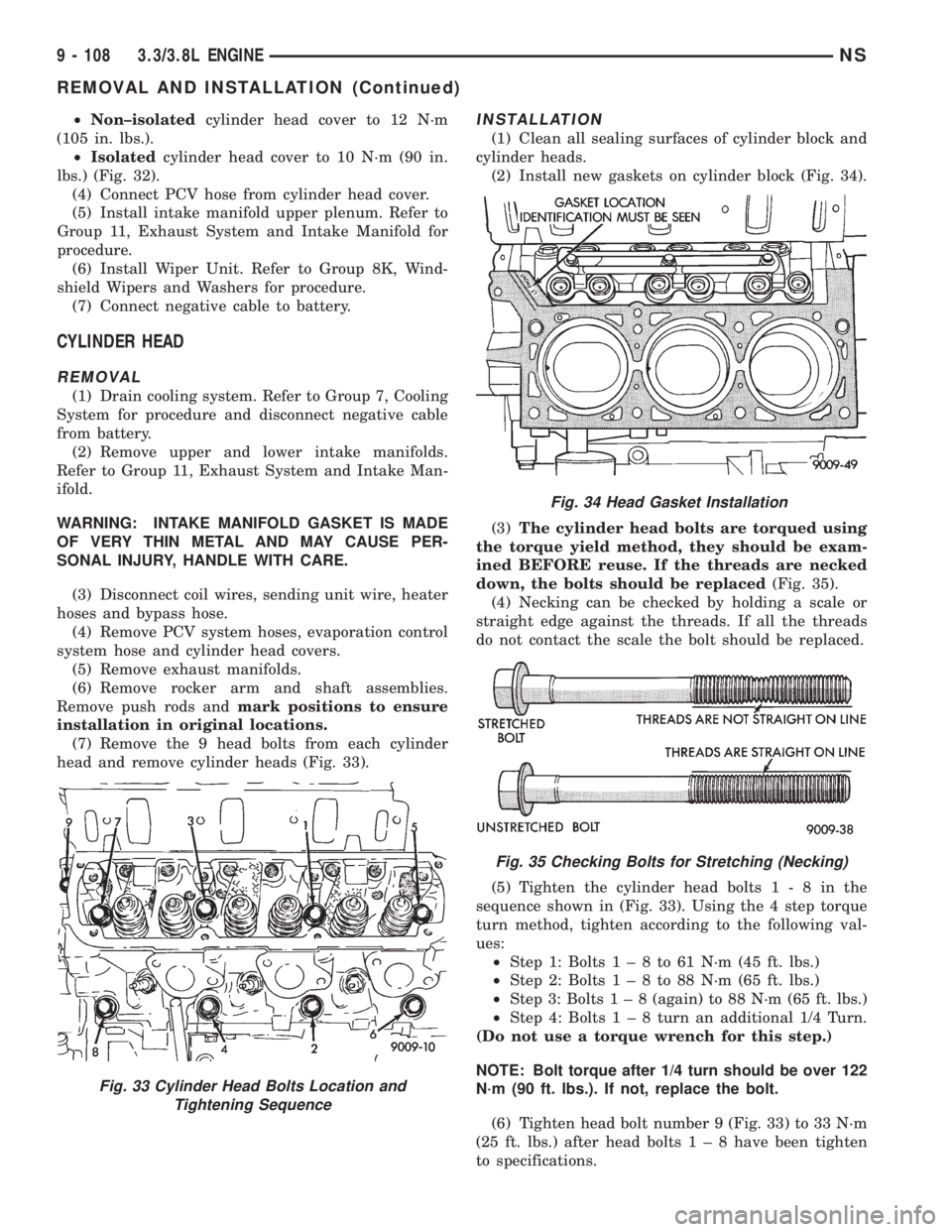
(7) Remove the 9 head bolts from each cylinder
head and remove cylinder heads (Fig. 33).
INSTALLATION
(1) Clean all sealing surfaces of cylinder block and
cylinder heads.
(2) Install new gaskets on cylinder block (Fig. 34).
(3)The cylinder head bolts are torqued using
the torque yield method, they should be exam-
ined BEFORE reuse. If the threads are necked
down, the bolts should be replaced(Fig. 35).
(4) Necking can be checked by holding a scale or
straight edge against the threads. If all the threads
do not contact the scale the bolt should be replaced.
(5) Tighten the cylinder head bolts1-8inthe
sequence shown in (Fig. 33). Using the 4 step torque
turn method, tighten according to the following val-
ues:
²Step 1: Bolts1±8to61N´m(45ft.lbs.)
²Step 2: Bolts1±8to88N´m(65ft.lbs.)
²Step 3: Bolts1±8(again) to 88 N´m (65 ft. lbs.)
²Step 4: Bolts1±8turn an additional 1/4 Turn.
(Do not use a torque wrench for this step.)
NOTE: Bolt torque after 1/4 turn should be over 122
N´m (90 ft. lbs.). If not, replace the bolt.
(6) Tighten head bolt number 9 (Fig. 33) to 33 N´m
(25 ft. lbs.) after head bolts1±8have been tighten
to specifications.
Fig. 33 Cylinder Head Bolts Location and
Tightening Sequence
Fig. 34 Head Gasket Installation
Fig. 35 Checking Bolts for Stretching (Necking)
9 - 108 3.3/3.8L ENGINENS
REMOVAL AND INSTALLATION (Continued)
Page 1736 of 1938

(16) Clean access urethane from exterior with
MopartSuper Kleen or equivalent.
(17) Apply 150 mm (6 in.) lengths of 50 mm (2 in.)
masking tape spaced 250 mm (10 in.) apart to hold
molding in place until urethane cures.
(18) Engage wire connectors to windshield
defroster grid.
(19) Install A-pillar trim panels.
(20) Install cowl cover and wipers.
(21) Install inside rear view mirror.
(22) After urethane has cured, remove tape strips
and water test windshield to verify repair.
BODY SIDE/SLIDING DOOR STATIONARY GLASS
The temperature of the vehicle should be at least
21É C (70É F) before removing the stationary quarter/
sliding door glass. Butyl sealer becomes more pliable
at high temperatures.
REMOVAL
(1) Remove interior trim as necessary to gain
access attaching locations on back of glass.
(2) Remove nuts holding stationary glass to fence.
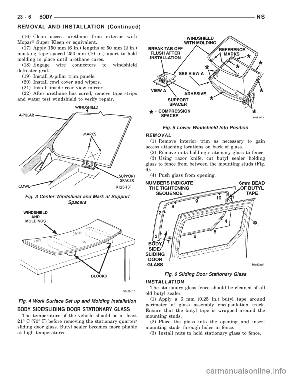
(3) Using razor knife, cut butyl sealer holding
glass to fence from between the mounting studs (Fig.
6).
(4) Push glass from opening.
INSTALLATION
The stationary glass fence should be cleaned of all
old butyl sealer.
(1) Applya6mm(0.25 in.) butyl tape around
perimeter of glass assembly encapsulation track.
Ensure that the butyl tape is wrapped around the
mounting studs.
(2) Place the glass into the opening and insert
mounting studs through holes in fence.
(3) Install nuts to hold stationary glass to fence.
Fig. 3 Center Windshield and Mark at Support
Spacers
Fig. 4 Work Surface Set up and Molding Installation
Fig. 5 Lower Windshield Into Position
Fig. 6 Sliding Door Stationary Glass
23 - 6 BODYNS
REMOVAL AND INSTALLATION (Continued)