1996 CHRYSLER VOYAGER oil capacity
[x] Cancel search: oil capacityPage 1632 of 1938
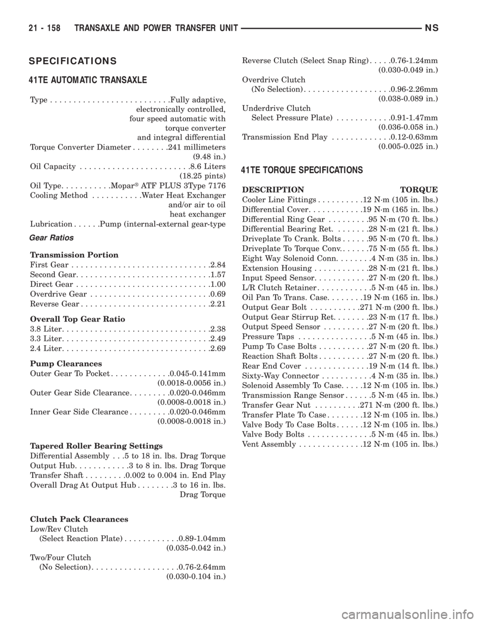
SPECIFICATIONS
41TE AUTOMATIC TRANSAXLE
Type..........................Fully adaptive,
electronically controlled,
four speed automatic with
torque converter
and integral differential
Torque Converter Diameter........241 millimeters
(9.48 in.)
Oil Capacity........................8.6 Liters
(18.25 pints)
OilType...........MopartATF PLUS 3Type 7176
Cooling Method...........Water Heat Exchanger
and/or air to oil
heat exchanger
Lubrication......Pump (internal-external gear-type
Gear Ratios
Transmission Portion
First Gear..............................2.84
Second Gear.............................1.57
Direct Gear.............................1.00
Overdrive Gear..........................0.69
Reverse Gear............................2.21
Overall Top Gear Ratio
3.8 Liter................................2.38
3.3 Liter................................2.49
2.4 Liter................................2.69
Pump Clearances
Outer Gear To Pocket.............0.045-0.141mm
(0.0018-0.0056 in.)
Outer Gear Side Clearance.........0.020-0.046mm
(0.0008-0.0018 in.)
Inner Gear Side Clearance.........0.020-0.046mm
(0.0008-0.0018 in.)
Tapered Roller Bearing Settings
Differential Assembly . . .5 to 18 in. lbs. Drag Torque
Output Hub............3to8in.lbs. Drag Torque
Transfer Shaft.........0.002 to 0.004 in. End Play
Overall Drag At Output Hub........3to16in.lbs.
Drag Torque
Clutch Pack Clearances
Low/Rev Clutch
(Select Reaction Plate)............0.89-1.04mm
(0.035-0.042 in.)
Two/Four Clutch
(No Selection)...................0.76-2.64mm
(0.030-0.104 in.)Reverse Clutch (Select Snap Ring).....0.76-1.24mm
(0.030-0.049 in.)
Overdrive Clutch
(No Selection)...................0.96-2.26mm
(0.038-0.089 in.)
Underdrive Clutch
Select Pressure Plate)............0.91-1.47mm
(0.036-0.058 in.)
Transmission End Play.............0.12-0.63mm
(0.005-0.025 in.)
41TE TORQUE SPECIFICATIONS
DESCRIPTION TORQUE
Cooler Line Fittings..........12N´m(105 in. lbs.)
Differential Cover............19N´m(165 in. lbs.)
Differential Ring Gear.........95N´m(70ft.lbs.)
Differential Bearing Ret........28N´m(21ft.lbs.)
Driveplate To Crank. Bolts......95N´m(70ft.lbs.)
Driveplate To Torque Conv.......75N´m(55ft.lbs.)
Eight Way Solenoid Conn........4N´m(35in.lbs.)
Extension Housing............28N´m(21ft.lbs.)
Input Speed Sensor............27N´m(20ft.lbs.)
L/R Clutch Retainer............5N´m(45in.lbs.)
Oil Pan To Trans. Case........19N´m(165 in. lbs.)
Output Gear Bolt...........271 N´m (200 ft. lbs.)
Output Gear Stirrup Ret........23N´m(17ft.lbs.)
Output Speed Sensor..........27N´m(20ft.lbs.)
Pressure Taps................5N´m(45in.lbs.)
Pump To Case Bolts...........27N´m(20ft.lbs.)
Reaction Shaft Bolts...........27N´m(20ft.lbs.)
Rear End Cover..............19N´m(14ft.lbs.)
Sixty-Way Connector...........4N´m(35in.lbs.)
Solenoid Assembly To Case.....12N´m(105 in. lbs.)
Transmission Range Sensor......5N´m(45in.lbs.)
Transfer Gear Nut..........271 N´m (200 ft. lbs.)
Transfer Plate To Case........12N´m(105 in. lbs.)
Valve Body To Case Bolts......12N´m(105 in. lbs.)
Valve Body Bolts..............5N´m(45in.lbs.)
Vent Assembly..............12N´m(105 in. lbs.)
21 - 158 TRANSAXLE AND POWER TRANSFER UNITNS
Page 1660 of 1938
²Improper operation
HARD SHIFTING
Hard shifting may be caused by a misadjusted
crossover cable. If hard shifting is accompanied by
gear clash, synchronizer clutch and stop rings or gear
teeth may be worn or damaged.
Misassembled synchronizer components also cause
shifting problems. Incorrectly installed synchronizer
sleeves, struts, or springs can cause shift problems.
NOISY OPERATION
Transaxle noise is most often a result of worn or
damaged components. Chipped, broken gear or syn-
chronizer teeth, and brinnelled, spalled bearings all
cause noise.
Abnormal wear and damage to the internal compo-
nents is frequently the end result of insufficient
lubricant.
SLIPS OUT OF GEAR
Transaxle disengagement may be caused by mis-
aligned or damaged shift components, or worn teeth
on the drive gears or synchronizer components. Incor-
rect assembly also causes gear disengagement.
LOW LUBRICANT LEVEL
Insufficient transaxle lubricant is usually the
result of leaks, or inaccurate fluid level check or refill
method. Leakage is evident by the presence of oil
around the leak point. If leakage is not evident, the
condition is probably the result of an underfill.
If air±powered lubrication equipment is used to fill
a transaxle, be sure the equipment is properly cali-
brated. Equipment out of calibration can lead to an
underfill condition.
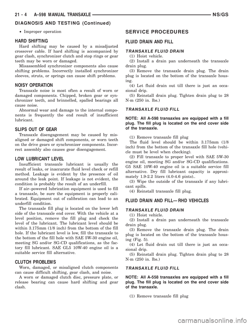
The transaxle fill plug is located on the lower left
side of the transaxle end cover. With the vehicle at a
level position, remove the fill plug and check the
level of the lubricant. The lubricant level should be
within 3.175mm (1/8 inch) from the bottom of the fill
hole. If the lubricant level is low, fill the transaxle to
the bottom of the fill hole with SAE 5W-30 engine oil,
meeting SG and/or SG-CD qualifications, as the fac-
tory fill lubricant. SAE GL5 10W-40 engine oil is a
suitable service fill alternative.
CLUTCH PROBLEMS
Worn, damaged, or misaligned clutch components
can cause difficult shifting, gear clash, and noise.
A worn or damaged clutch disc, pressure plate, or
release bearing can cause hard shifting and gear
clash.
SERVICE PROCEDURES
FLUID DRAIN AND FILL
TRANSAXLE FLUID DRAIN
(1) Hoist vehicle.
(2) Install a drain pan underneath the transaxle
drain plug.
(3) Remove the transaxle drain plug. The drain
plug is located on the bottom of the transaxle hous-
ing.
(4) Let fluid drain out till there is just an occa-
sional drip.
(5) Reinstall drain plug. Tighten drain plug to 28
N´m (250 in. lbs.)
TRANSAXLE FLUID FILL
NOTE: All A-598 transaxles are equipped with a fill
plug. The fill plug is located on the end cover side
of the transaxle.
(1) Remove transaxle fill plug
The fluid level should be within 3.175mm (1/8
inch) from the bottom of the transaxle fill hole (vehi-
cle must be level when checking).
(2) Fill transaxle to proper level with SAE 5W-30
engine oil, meeting SG and/or SG-CD qualifications.
G5 SAE 10W-40 engine oil is a suitable service fill
alternative. Dry fill lubricant capacity is approxi-
mately 1.9-2.2 liters (4.0-4.6 pints)..
(3) Wipe the outside of the transaxle if any lubri-
cant spills.
(4) Reinstall transaxle fill plug.
FLUID DRAIN AND FILLÐRHD VEHICLES
TRANSAXLE FLUID DRAIN
(1) Hoist vehicle.
(2) Install a drain pan underneath the transaxle
drain plug.
(3) Remove the transaxle drain plug. The drain
plug is located on the bottom of the transaxle hous-
ing (Fig. 5).
(4) Let fluid drain out till there is just an occa-
sional drip.
(5) Reinstall drain plug. Tighten drain plug to 28
N´m (250 in. lbs.)
TRANSAXLE FLUID FILL
NOTE: All A-558 transaxles are equipped with a fill
plug. The fill plug is located on the end cover side
of the transaxle.
(1) Remove transaxle fill plug
21 - 4 A±598 MANUAL TRANSAXLENS/GS
DIAGNOSIS AND TESTING (Continued)
Page 1661 of 1938
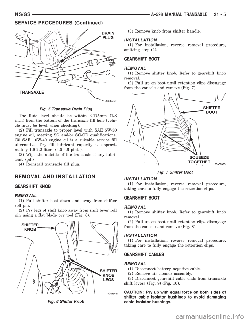
The fluid level should be within 3.175mm (1/8
inch) from the bottom of the transaxle fill hole (vehi-
cle must be level when checking).
(2) Fill transaxle to proper level with SAE 5W-30
engine oil, meeting SG and/or SG-CD qualifications.
G5 SAE 10W-40 engine oil is a suitable service fill
alternative. Dry fill lubricant capacity is approxi-
mately 1.9-2.2 liters (4.0-4.6 pints).
(3) Wipe the outside of the transaxle if any lubri-
cant spills.
(4) Reinstall transaxle fill plug.
REMOVAL AND INSTALLATION
GEARSHIFT KNOB
REMOVAL
(1) Pull shifter boot down and away from shifter
roll pin.
(2) Pry legs of shift knob away from shift lever roll
pin using a flat blade pry tool (Fig. 6).(3) Remove knob from shifter handle.
INSTALLATION
(1) For installation, reverse removal procedure,
omitting step (2).
GEARSHIFT BOOT
REMOVAL
(1) Remove shifter knob. Refer to gearshift knob
removal.
(2) Pull up on boot until retention clips disengage
from the console and remove (Fig. 7).
INSTALLATION
(1) For installation, reverse removal procedure,
taking care to fully engage the retention clips.
GEARSHIFT BOOT
REMOVAL
(1) Remove shifter knob. Refer to gearshift knob
removal.
(2) Pull up on boot until retention clips disengage
from the console and remove (Fig. 8).
INSTALLATION
(1) For installation, reverse removal procedure,
taking care to fully engage the retention clips.
GEARSHIFT CABLES
REMOVAL
(1) Disconnect battery negative cable.
(2) Remove air cleaner assembly.
(3) Disconnect gearshift cable ends from transaxle
shift levers (Fig. 9) (Fig. 10).
CAUTION: Pry up with equal force on both sides of
shifter cable isolator bushings to avoid damaging
cable isolator bushings.
Fig. 5 Transaxle Drain Plug
Fig. 6 Shifter Knob
Fig. 7 Shifter Boot
NS/GSA±598 MANUAL TRANSAXLE 21 - 5
SERVICE PROCEDURES (Continued)
Page 1819 of 1938
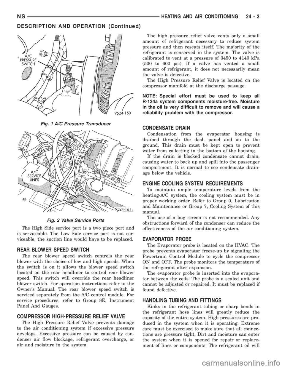
The High Side service port is a two piece port and
is serviceable. The Low Side service port is not ser-
viceable, the suction line would have to be replaced.
REAR BLOWER SPEED SWITCH
The rear blower speed switch controls the rear
blower with the choice of low and high speeds. When
the switch is on it allows the blower speed switch
located on the rear headliner to control rear blower
speed. This switch will override the rear headliner
blower switch. For operation instructions refer to the
Owner's Manual. The rear blower speed switch is
serviced separately from the A/C control module. For
service procedures, refer to Group 8E, Instrument
Panel And Gauges.
COMPRESSOR HIGH-PRESSURE RELIEF VALVE
The High Pressure Relief Valve prevents damage
to the air conditioning system if excessive pressure
develops. Excessive pressure can be caused by con-
denser air flow blockage, refrigerant overcharge, or
air and moisture in the system.The high pressure relief valve vents only a small
amount of refrigerant necessary to reduce system
pressure and then reseats itself. The majority of the
refrigerant is conserved in the system. The valve is
calibrated to vent at a pressure of 3450 to 4140 kPa
(500 to 600 psi). If a valve has vented a small
amount of refrigerant, it does not necessarily mean
the valve is defective.
The High Pressure Relief Valve is located on the
compressor manifold at the discharge passage.
NOTE: Special effort must be used to keep all
R-134a system components moisture-free. Moisture
in the oil is very difficult to remove and will cause a
reliability problem with the compressor.
CONDENSATE DRAIN
Condensation from the evaporator housing is
drained through the dash panel and on to the
ground. This drain must be kept open to prevent
water from collecting in the bottom of the housing.
If the drain is blocked condensate cannot drain,
causing water to back up and spill into the passenger
compartment. It is normal to see condensate drain-
age below the vehicle.
ENGINE COOLING SYSTEM REQUIREMENTS
To maintain ample temperature levels from the
heating-A/C system, the cooling system must be in
proper working order. Refer to Group 0, Lubrication
and Maintenance or Group 7, Cooling System of this
manual.
The use of a bug screen is not recommended. Any
obstructions forward of the condenser can reduce the
effectiveness of the air conditioning system.
EVAPORATOR PROBE
The Evaporator probe is located on the HVAC. The
probe prevents evaporator freeze-up by signaling the
Powertrain Control Module to cycle the compressor
ON and OFF. The probe monitors the temperature of
the refrigerant after expansion.
The evaporator probe is inserted into the evapora-
tor between the coils. The probe is a sealed unit and
cannot be adjusted or repaired. It must be replaced if
found defective.
HANDLING TUBING AND FITTINGS
Kinks in the refrigerant tubing or sharp bends in
the refrigerant hose lines will greatly reduce the
capacity of the entire system. High pressures are pro-
duced in the system when it is operating. Extreme
care must be exercised to make sure that all connec-
tions are pressure tight. Dirt and moisture can enter
the system when it is opened for repair or replace-
ment of lines or components. The refrigerant oil will
Fig. 1 A/C Pressure Transducer
Fig. 2 Valve Service Ports
NSHEATING AND AIR CONDITIONING 24 - 3
DESCRIPTION AND OPERATION (Continued)
Page 1821 of 1938
unit housing. On air conditioned vehicles, the air
passes through the evaporator. At this point the air
flow can be directed either through or around the
heater core. This is done by adjusting the blend- air
door with the TEMP control on the control head. An
optional zone control HVAC control module is avail-
able. This unit has dual blend-air doors that can be
regulated independently of each other. The tempera-
ture setting can be different from driver's side to pas-
senger side. After the air passes the blend-air door(s),
the air flow can then be directed from the Panel,
Floor, and Defrost outlets. Air flow velocity can be
adjusted with the blower speed selector switch on the
control head.
Ambient air intake can be shut off by closing the
recirculating air door. This will recirculate the air
that is already inside the vehicle. This is done by
depressing the Recirc. button on the control head. On
air conditioned vehicles, moving the control to Mix or
Defrost depresses the A/C button and will engage the
compressor. This will send refrigerant through the
evaporator, and remove heat and humidity from the
air before it goes through the heater core.
CAUTION: In cold weather, use of the Recirculation
mode may lead to excessive window fogging. The
Recirculation mode is automatically deactivated in
Mix and Defrost modes to improve window clearing
operation.
SYSTEM OIL LEVEL
It is important to have the correct amount of oil in
the A/C system to ensure proper lubrication of the
compressor. Too little oil will result in damage to the
compressor. Too much oil will reduce the cooling
capacity of the system and consequently result in
higher discharge air temperatures.NOTE: The oil used in the compressor is ND8 PAG
R134a refrigerant oil. Only refrigerant oil of the
same type should be used to service the system.
Do not use any other oil. The oil container should
be kept tightly capped until it is ready for use.
Tightly cap afterwards to prevent contamination
from dirt and moisture. Refrigerant oil will quickly
absorb any moisture it comes in contact with. Spe-
cial effort must be used to keep all R-134a system
components moisture-free. Moisture in the oil is
very difficult to remove and will cause a reliability
problem with the compressor.
It will not be necessary to check oil level in the
compressor or to add oil unless there has been an oil
loss. Oil loss at a leak point will be evident by the
presence of a wet, shiny surface around the leak.
REFRIGERANT OIL LEVEL CHECK
When an air conditioning system is first assem-
bled, all components (except the compressor) are
refrigerant oil free. After the system has been
charged with R134a refrigerant and operated, the oil
in the compressor is dispersed through the lines and
components. The evaporator, condenser, and filter-
drier will retain a significant amount of oil, refer to
the Refrigerant Oil Capacities chart. When a compo-
nent is replaced, the specified amount of refrigerant
oil must be added. When the compressor is replaced,
the amount of oil that is retained in the rest of the
system must be drained from the replacement com-
pressor. When a line or component has ruptured and
oil has escaped, the compressor should be removed
and drained. The filter-drier must be replaced along
with the ruptured part. The oil capacity of the sys-
tem, minus the amount of oil still in the remaining
components, can be measured and poured into the
suction port of the compressor.
Example: On a dual system the evaporator retains
60 ml (2 oz). The condenser retains 30 ml (1 oz) of
oil, and system capacity may be 220 ml (7.40 oz) of
oil.
220 ml minus 90 ml = 130 ml (4.40 oz).
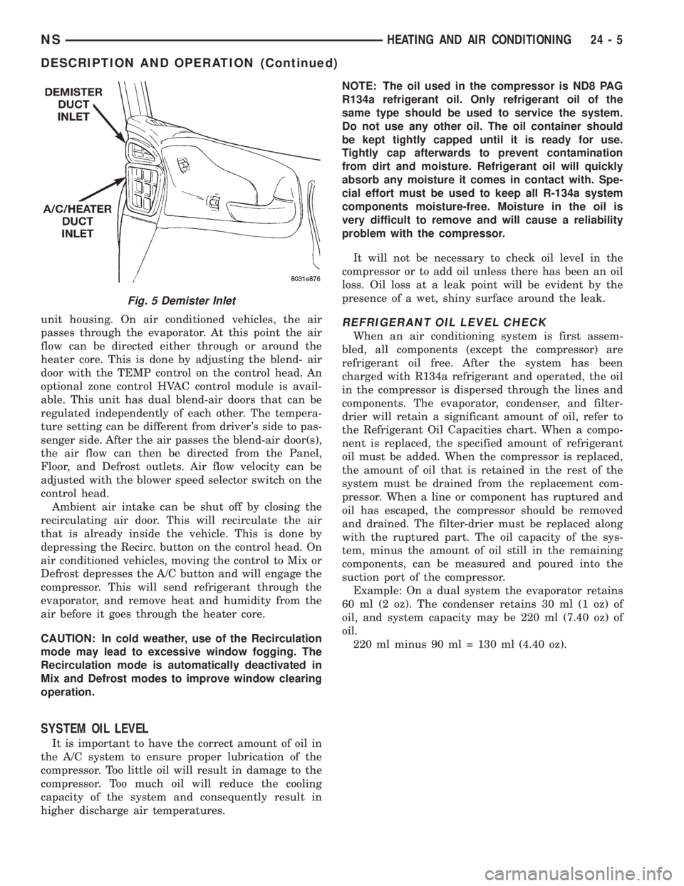
Fig. 5 Demister Inlet
NSHEATING AND AIR CONDITIONING 24 - 5
DESCRIPTION AND OPERATION (Continued)
Page 1822 of 1938

CAUTION: The refrigerant oil used in a R-134a A/C
system is unique. Use only oils which were
designed to work with R-134a refrigerant. The oil
designated for this vehicle is ND8 PAG (polyalka-
lene glycol).
SERVICING REFRIGERANT OIL LEVEL
(1) Using a refrigerant recovery machine, remove
refrigerant from the A/C system.
(2) Remove refrigerant lines from A/C compressor.
(3) Remove compressor from vehicle.
(4) From suction port on top of compressor, drain
refrigerant oil from compressor.
(5) Add system capacity minus the capacity of
components that have not been replaced through suc-
tion port on compressor. Refer to the Refrigerant Oil
Capacity Chart.
(6) Install compressor, connect refrigerant lines,
evacuate, and charge refrigerant system.
DIAGNOSIS AND TESTING
ACTUATOR CALIBRATION/DIAGNOSTICS AND
COOLDOWN TEST
GENERAL INFORMATION
If the HVAC control module is replaced, the Cali-
bration Diagnostic and Cooldown tests will need to
be performed. Once this group of tests have success-
fully passed, they can be performed individually. The
engine must be running during the test to provide
hot coolant for the heater, A/C compressor operation
and to assure that the actuators are calibrated cor-
rectly. The HVAC control module is capable of trou-
bleshooting the system in approximately 120 seconds.
If a condition is detected, an error code is displayed.
The error code cannot be erased until the condition is
repaired and the diagnostic test is performed. Check
wire before replacing components, refer to Group 8W,
Wiring Diagrams.CAUTION: Do not remove the actuators from the
Heater-A/C unit assembly with power applied.
Removal should only be done with the Ignition OFF.
The actuators have no mechanical stops to limit the
travel. If the actuator rotates and is not connected
to the unit assembly, it will become out of calibra-
tion.
ACTUATOR CALIBRATION
Mode, Blend and Zone (if equipped) door calibra-
tion compensates for mechanical variations in the
actuators, HVAC control module and its linkages. In-
vehicle calibration can be entered from the control's
front panel. If the REAR WIPE and INTERMIT-
TENT LED's flash simultaneously when Ignition is
cycled ON, the actuators have not been calibrated or
during the previous calibration a failure occurred
(Fig. 6) and (Fig. 7). Diagnostics will always occur
during Calibration Diagnostic and Cooldown test.
REFRIGERANT OIL CAPACITIES
Refrigerant
Oil Capaci-
tiesFront A/C Dual A/C
Component ml oz ml oz
Compressor 150 ml 5.0 oz 220 ml 7.4 oz
Filter-Drier 30 ml 1.0 oz 30 ml 1.0 oz
Condenser 30 ml 1.0 oz 30 ml 1.0 oz
Evaporator 60 ml 2.0 oz 60 ml 2 .0 oz
Rear Evap. N/A N/A 60 ml 2.0 oz
Fig. 6 Radio Bezel and HVAC Control
24 - 6 HEATING AND AIR CONDITIONINGNS
DESCRIPTION AND OPERATION (Continued)
Page 1869 of 1938
pressor is driven off the back of the power steering
pump. A rubber flex coupling transfers the power from
the power steering pump to the compressor clutch.
COMPRESSOR HIGH-PRESSURE RELIEF VALVE
The High Pressure Relief Valve prevents damage
to the air conditioning system if excessive pressure
develops. Excessive pressure can be caused by con-
denser air flow blockage, refrigerant overcharge, or
air and moisture in the system.
The high pressure relief valve vents only a small
amount of refrigerant necessary to reduce system
pressure and then reseats itself. The majority of the
refrigerant is conserved in the system. The valve is
calibrated to vent at a pressure of 3450 to 4140 kPa
(500 to 600 psi). If a valve has vented a small
amount of refrigerant, it does not necessarily mean
the valve is defective.
The High Pressure Relief Valve is located on the
compressor manifold at the discharge passage.
NOTE: Special effort must be used to keep all
R-134a system components moisture-free. Moisture
in the oil is very difficult to remove and will cause a
reliability problem with the compressor.
CONDENSATE DRAIN
Condensation from the evaporator housing is
drained through the dash panel and on to the
ground. This drain must be kept open to prevent
water from collecting in the bottom of the housing.
If the drain is blocked condensate cannot drain,
causing water to back up and spill into the passenger
compartment. It is normal to see condensate drain-
age below the vehicle.
ENGINE COOLING SYSTEM REQUIREMENTS
To maintain ample temperature levels from the
heating-A/C system, the cooling system must be in
proper working order. Refer to Group 0, Lubrication
and Maintenance or Group 7, Cooling System of this
manual.
The use of a bug screen is not recommended. Any
obstructions forward of the condenser can reduce the
effectiveness of the air conditioning system.
EVAPORATOR PROBE
The Evaporator probe is located on the HVAC. The
probe prevents evaporator freeze-up by signaling the
Powertrain Control Module to cycle the compressor
ON and OFF. The probe monitors the temperature of
the refrigerant after expansion.
The evaporator probe is inserted into the evapora-
tor between the coils. The probe is a sealed unit and
cannot be adjusted or repaired. It must be replaced if
found defective.
HANDLING TUBING AND FITTINGS
Kinks in the refrigerant tubing or sharp bends in
the refrigerant hose lines will greatly reduce the
capacity of the entire system. High pressures are pro-
duced in the system when it is operating. Extreme
care must be exercised to make sure that all connec-
tions are pressure tight. Dirt and moisture can enter
the system when it is opened for repair or replace-
ment of lines or components. The refrigerant oil will
absorb moisture readily out of the air. This moisture
will convert into acids within a closed system.
CAUTION: The system must be completely empty
before opening any fitting or connection in the
refrigeration system. Open fittings with caution
even after the system has been emptied. If any
pressure is noticed as a fitting is loosened,
retighten fitting and evacuate the system again.
A good rule for the flexible hose lines is to keep
the radius of all bends at least 10 times the diame-
ter of the hose. Sharper bends will reduce the flow
of refrigerant. The flexible hose lines should be
routed so they are at least 3 inches (80 mm) from
the exhaust manifold. Inspect all flexible hose lines
to make sure they are in good condition and prop-
erly routed.
The use of correct wrenches when making con-
nections is very important. Improper wrenches or
improper use of wrenches can damage the fittings.
The internal parts of the A/C system will remain
stable as long as moisture-free refrigerant and
refrigerant oil is used. Abnormal amounts of dirt,
moisture or air can upset the chemical stability.
This may cause operational troubles or even seri-
ous damage if present in more than very small
quantities.
When opening a refrigeration system, have every-
thing you will need to repair the system ready. This
will minimize the amount of time the system must
be opened. Cap or plug all lines and fittings as
soon as they are opened. This will help prevent the
entrance of dirt and moisture. All new lines and
components should be capped or sealed until they
are ready to be used.
All tools, including the refrigerant dispensing
manifold, the manifold gauge set, and test hoses
should be kept clean and dry.
HVAC CONTROL MODULE
The HVAC control module regulates the operation
of the various actuator motors. The actuator motors
are used to move the mode, blend- air, and recirc.
doors (Fig. 2).
The control module is included in the A/C control
head located on the instrument panel. The control
head includes the blower speed switch, rear wiper
NS/GSHEATING AND AIR CONDITIONING 24 - 3
DESCRIPTION AND OPERATION (Continued)
Page 1871 of 1938
capacity of the system and consequently result in
higher discharge air temperatures.
NOTE: The oil used in the Denso 2.5L Turbo Diesel
and the Denso 2.0L gasoline engine compressors is
ND-8 PAG R134a refrigerant oil. Only refrigerant oil
of the same type should be used to service the sys-
tem. Do not use any other oil. The oil container
should be kept tightly capped until it is ready for
use. Tightly cap afterwards to prevent contamina-
tion from dirt and moisture. Refrigerant oil will
quickly absorb any moisture it comes in contact
with. Special effort must be used to keep all R-134a
system components moisture-free. Moisture in the
oil is very difficult to remove and will cause a reli-
ability problem with the compressor.
It will not be necessary to check oil level in the
compressor or to add oil unless there has been an oil
loss. Oil loss at a leak point will be evident by the
presence of a wet, shiny surface around the leak.
REFRIGERANT OIL LEVEL CHECK
When an air conditioning system is first assem-
bled, all components (except the compressor) are
refrigerant oil free. After the system has been
charged with R134a refrigerant and operated, the oil
in the compressor is dispersed through the lines and
components. The evaporator, condenser, and filter-
drier will retain a significant amount of oil, refer to
the Refrigerant Oil Capacities chart. When a compo-
nent is replaced, the specified amount of refrigerant
oil must be added. When the compressor is replaced,
the amount of oil that is retained in the rest of the
system must be drained from the replacement com-
pressor. When a line or component has ruptured and
oil has escaped, the compressor should be removed
and drained. The compressor is drained through the
suction port or by removing the sump bolt on top of
the compressor, refer to Compressor Removal and
Installation procedures. The filter-drier must be
replaced along with the ruptured part. The oil capac-
ity of the system, minus the amount of oil still in the
remaining components, can be measured and poured
into the suction port of the compressor.
Example: The evaporator retains 50 ml (1.7 oz.).
The condenser retains 30 ml (1 oz) of oil, and system
capacity may be 220 ml (7.40 oz) of oil.
220 ml minus 90 ml = 130 ml (4.40 oz.).
CAUTION: The refrigerant oil used in a R-134a A/C
system is unique. Use only oils which were designed
to work with R-134a refrigerant. The oil designated
for the Denso 2.5L Turbo Diesel and Denso 2.0L gas-
oline engine compressors is ND-8 PAG compressor
oil. For gasoline vehicles still using R-12 refrigerant,
use ND8 PAG compressor oil.
SERVICING REFRIGERANT OIL LEVEL
(1) Using a refrigerant recovery machine, remove
refrigerant from the A/C system.
(2) Remove refrigerant lines from A/C compressor.
(3) Remove compressor from vehicle.
(4) From suction port on top of compressor, drain
refrigerant oil from compressor.
(5) Add system capacity minus the capacity of
components that have not been replaced through suc-
tion port on compressor. Refer to the Refrigerant Oil
Capacity Chart.
(6) Install compressor, connect refrigerant lines,
evacuate, and charge refrigerant system.
DIAGNOSIS AND TESTING
ACTUATOR CALIBRATION/DIAGNOSTICS AND
COOLDOWN TEST
GENERAL INFORMATION
If the HVAC control module is replaced, the Cali-
bration Diagnostic and Cooldown tests will need to
be performed. Once this group of tests have success-
fully passed, they can be performed individually. The
engine must be running during the test to provide
hot coolant for the heater, A/C compressor operation
and to assure that the actuators are calibrated cor-
rectly. The HVAC control module is capable of trou-
bleshooting the system in approximately 120 seconds.
If a condition is detected, an error code is displayed.
The error code cannot be erased until the condition is
repaired and the diagnostic test is performed. Check
wire before replacing components, refer to Group 8W,
Wiring Diagrams.
CAUTION: Do not remove the actuators from the
Heater-A/C unit assembly with power applied.
Removal should only be done with the Ignition OFF.
The actuators have no mechanical stops to limit the
travel. If the actuator rotates and is not connected to
the unit assembly, it will become out of calibration.
ACTUATOR CALIBRATION
Mode, Blend and Zone (if equipped) door calibra-
tion compensates for mechanical variations in the
REFRIGERANT OIL CAPACITIES
REFRIGERANT OIL CAPACITIES
COMPONENT ML OZ
Compressor 135 ml 4.5 oz
Filter-Drier 30 ml 1.0 oz
Condenser 30 ml 1.0 oz
Evaporator 50 ml 1.7 oz
NS/GSHEATING AND AIR CONDITIONING 24 - 5
DESCRIPTION AND OPERATION (Continued)