1996 CHRYSLER VOYAGER service reset
[x] Cancel search: service resetPage 1374 of 1938

Actual electric fuel timing (amount of advance) is
accomplished by the fuel timing solenoid mounted to
the bottom of the injection pump (Fig. 5). Fuel timing
will be adjusted by the PCM, which controls the fuel
timing solenoid.
An overflow valve is attached into the fuel return
line at the rear of the fuel injection pump (Fig. 4).
This valve serves two purposes. One is to ensure that
a certain amount of residual pressure is maintained
within the pump when the engine is switched off.
This will prevent the fuel timing mechanism within
the injection pump from returning to its zero posi-
tion. The other purpose is to allow excess fuel to be
returned to the fuel tank through the fuel return
line. The pressure values within this valve are preset
and can not be adjusted.
The fuel injection pump supplies high±pressure
fuel of approximately 45,000 kPa (6526 psi) to each
injector in precise metered amounts at the correct
time.
For mechanical injection pump timing, refer to
Fuel Injection Pump Timing in the Service Proce-
dures section of this group.
FUEL INJECTORS
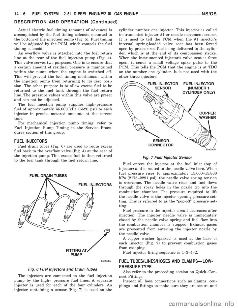
Fuel drain tubes (Fig. 6) are used to route excess
fuel back to the overflow valve (Fig. 4) at the rear of
the injection pump. This excess fuel is then returned
to the fuel tank through the fuel return line.
The injectors are connected to the fuel injection
pump by the high± pressure fuel lines. A separate
injector is used for each of the four cylinders. An
injector containing a sensor (Fig. 7) is used on thecylinder number one injector. This injector is called
instrumented injector #1 or needle movement sensor.
It is used to tell the PCM when the #1 injector's
internal spring-loaded valve seat has been forced
open by pressurized fuel being delivered to the cylin-
der, which is at the end of its compression stroke.
When the instrumented injector's valve seat is force
open, it sends a small voltage spike pulse to the
PCM. This tells the PCM that the engine is at TDC
on the number one cylinder. It is not used with the
other three injectors.
Fuel enters the injector at the fuel inlet (top of
injector) and is routed to the needle valve bore. When
fuel pressure rises to approximately 15,000±15,800
kPa (2175±2291 psi), the needle valve spring tension
is overcome. The needle valve rises and fuel flows
through the spray holes in the nozzle tip into the
combustion chamber. The pressure required to lift
the needle valve is the injector opening pressure set-
ting. This is referred to as the ªpop-offº pressure set-
ting.
Fuel pressure in the injector circuit decreases after
injection. The injector needle valve is immediately
closed by the needle valve spring and fuel flow into
the combustion chamber is stopped. Exhaust gases
are prevented from entering the injector nozzle by
the needle valve.
A copper washer (gasket) is used at the base of
each injector (Fig. 7) to prevent combustion gases
from escaping.
Fuel injector firing sequence is 1±3±4±2.
FUEL TUBES/LINES/HOSES AND CLAMPSÐLOW-
PRESSURE TYPE
Also refer to the proceeding section on Quick±Con-
nect Fittings.
Inspect all hose connections such as clamps, cou-
plings and fittings to make sure they are secure andFig. 6 Fuel Injectors and Drain Tubes
Fig. 7 Fuel Injector Sensor
14 - 6 FUEL SYSTEMÐ2.5L DIESEL ENGINE/2.0L GAS ENGINENS/GS
DESCRIPTION AND OPERATION (Continued)
Page 1375 of 1938

leaks are not present. The component should be
replaced immediately if there is any evidence of deg-
radation that could result in failure.
Never attempt to repair a plastic fuel line/tube or a
quick±connect fitting. Replace complete line/tube as
necessary.
Avoid contact of any fuel tubes/hoses with other
vehicle components that could cause abrasions or
scuffing. Be sure that the fuel lines/tubes are prop-
erly routed to prevent pinching and to avoid heat
sources.
The lines/tubes/hoses are of a special construction.
If it is necessary to replace these lines/tubes/hoses,
use only original equipment type.
The hose clamps used to secure the rubber hoses
are of a special rolled edge construction. This con-
struction is used to prevent the edge of the clamp
from cutting into the hose. Only these rolled edge
type clamps may be used in this system. All other
types of clamps may cut into the hoses and cause
fuel leaks.
Where a rubber hose is joined to a metal tube
(staked), do not attempt to repair. Replace entire
line/tube assembly.
Use new original equipment type hose clamps.
Tighten hose clamps to 2 N´m (20 in. lbs.) torque.
QUICK-CONNECT FITTINGSÐLOW PRESSURE
TYPE
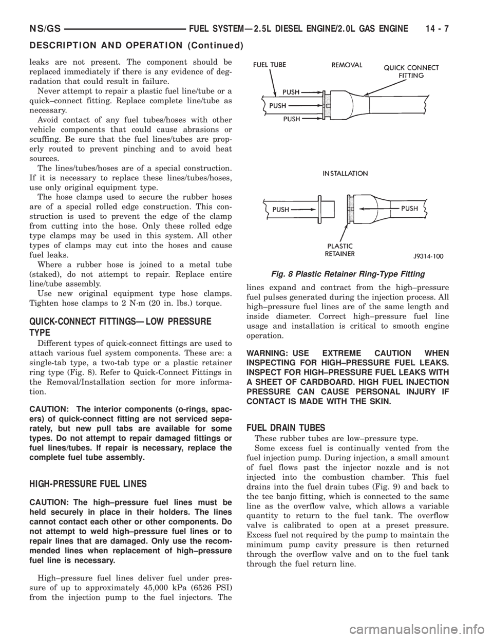
Different types of quick-connect fittings are used to
attach various fuel system components. These are: a
single-tab type, a two-tab type or a plastic retainer
ring type (Fig. 8). Refer to Quick-Connect Fittings in
the Removal/Installation section for more informa-
tion.
CAUTION: The interior components (o-rings, spac-
ers) of quick-connect fitting are not serviced sepa-
rately, but new pull tabs are available for some
types. Do not attempt to repair damaged fittings or
fuel lines/tubes. If repair is necessary, replace the
complete fuel tube assembly.
HIGH-PRESSURE FUEL LINES
CAUTION: The high±pressure fuel lines must be
held securely in place in their holders. The lines
cannot contact each other or other components. Do
not attempt to weld high±pressure fuel lines or to
repair lines that are damaged. Only use the recom-
mended lines when replacement of high±pressure
fuel line is necessary.
High±pressure fuel lines deliver fuel under pres-
sure of up to approximately 45,000 kPa (6526 PSI)
from the injection pump to the fuel injectors. Thelines expand and contract from the high±pressure
fuel pulses generated during the injection process. All
high±pressure fuel lines are of the same length and
inside diameter. Correct high±pressure fuel line
usage and installation is critical to smooth engine
operation.
WARNING: USE EXTREME CAUTION WHEN
INSPECTING FOR HIGH±PRESSURE FUEL LEAKS.
INSPECT FOR HIGH±PRESSURE FUEL LEAKS WITH
A SHEET OF CARDBOARD. HIGH FUEL INJECTION
PRESSURE CAN CAUSE PERSONAL INJURY IF
CONTACT IS MADE WITH THE SKIN.
FUEL DRAIN TUBES
These rubber tubes are low±pressure type.
Some excess fuel is continually vented from the
fuel injection pump. During injection, a small amount
of fuel flows past the injector nozzle and is not
injected into the combustion chamber. This fuel
drains into the fuel drain tubes (Fig. 9) and back to
the tee banjo fitting, which is connected to the same
line as the overflow valve, which allows a variable
quantity to return to the fuel tank. The overflow
valve is calibrated to open at a preset pressure.
Excess fuel not required by the pump to maintain the
minimum pump cavity pressure is then returned
through the overflow valve and on to the fuel tank
through the fuel return line.
Fig. 8 Plastic Retainer Ring-Type Fitting
NS/GSFUEL SYSTEMÐ2.5L DIESEL ENGINE/2.0L GAS ENGINE 14 - 7
DESCRIPTION AND OPERATION (Continued)
Page 1557 of 1938

²The shift lever position must stay until
prompted to shift to overdrive
²The shift lever position must stay in overdrive
after the Shift to Overdrive prompt until the DRBIII
indicates the procedure is complete
²The calculated oil temperature must be above
60É and below 200É
(1) Plug the DRBIII scan tool into the data link
connector. The connector is located under the instru-
ment panel.
(2) Go to the Transmission screen.
(3) Go to the Miscellaneous screen.
(4) Select Quick Learn Procedure. Follow the
instructions of the DRBIII to perform the Quick
Learn Procedure.
PINION FACTOR PROCEDURE
The vehicle speed readings for the speedometer are
taken from the output speed sensor. The TCM must
be calibrated to the different combinations of equip-
ment available. A procedure has been developed
called Pinion Factor. It allows the technician to set
the Transmission Control Module initial setting so
that the speedometer readings will be correct.
Failure to perform this procedure will cause a No
Speedometer Operation condition.
This procedure must be performed if the Transmis-
sion Control Module has been replaced.
To properly read or reset the Pinion Factor, it is
necessary to use a DRBIII scan tool. Perform the fol-
lowing steps with the DRBIII scan tool to read or
reset the Pinion Factor:
(1) Plug the DRBIII scan tool into the data link
connector located under the instrument panel.
(2) Select the Transmission menu.
(3) Select the Miscellaneous menu.
(4) Select Pinion Factor. Then follow the instruc-
tions on the DRBIII scan tool screen.
REMOVAL AND INSTALLATION
GEARSHIFT CABLE
REMOVAL
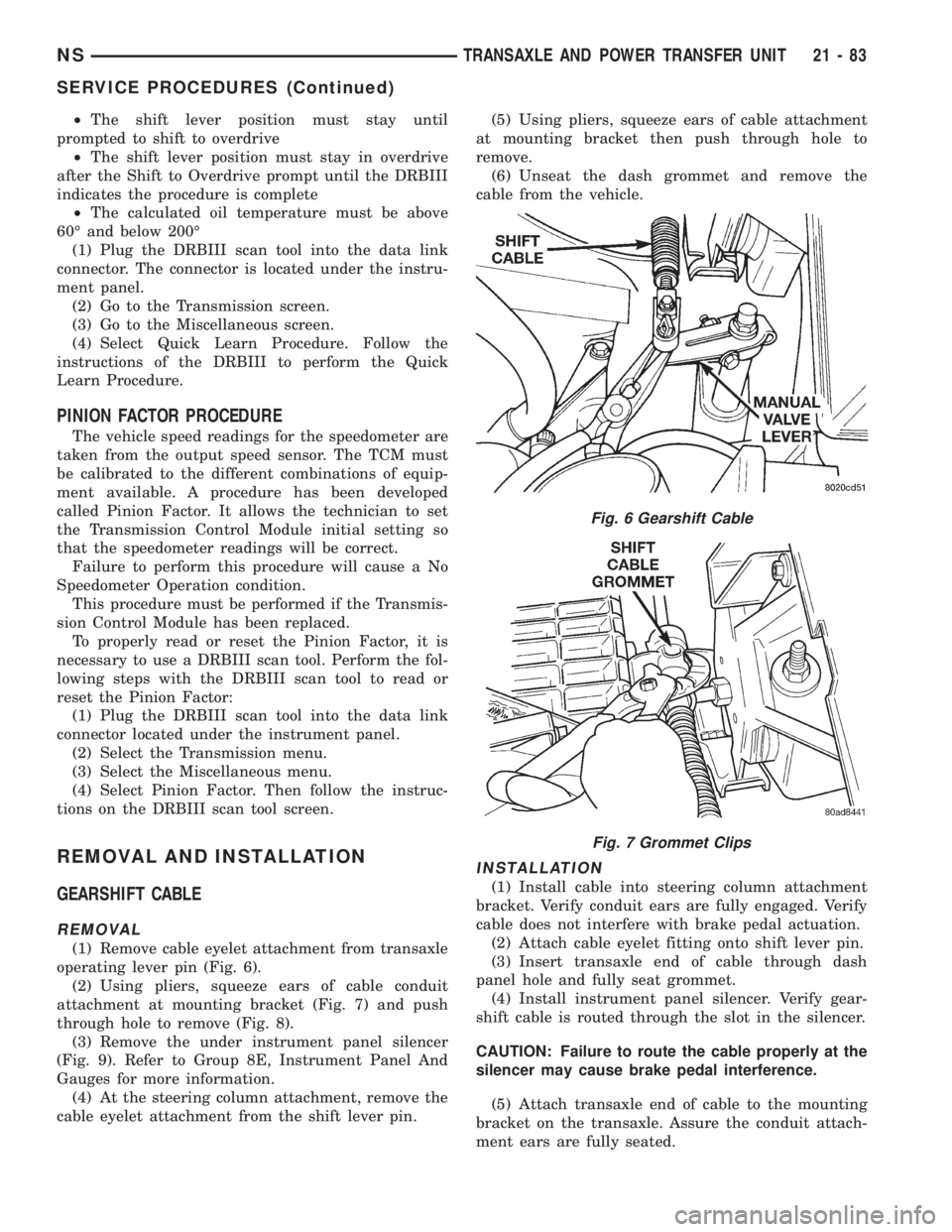
(1) Remove cable eyelet attachment from transaxle
operating lever pin (Fig. 6).
(2) Using pliers, squeeze ears of cable conduit
attachment at mounting bracket (Fig. 7) and push
through hole to remove (Fig. 8).
(3) Remove the under instrument panel silencer
(Fig. 9). Refer to Group 8E, Instrument Panel And
Gauges for more information.
(4) At the steering column attachment, remove the
cable eyelet attachment from the shift lever pin.(5) Using pliers, squeeze ears of cable attachment
at mounting bracket then push through hole to
remove.
(6) Unseat the dash grommet and remove the
cable from the vehicle.
INSTALLATION
(1) Install cable into steering column attachment
bracket. Verify conduit ears are fully engaged. Verify
cable does not interfere with brake pedal actuation.
(2) Attach cable eyelet fitting onto shift lever pin.
(3) Insert transaxle end of cable through dash
panel hole and fully seat grommet.
(4) Install instrument panel silencer. Verify gear-
shift cable is routed through the slot in the silencer.
CAUTION: Failure to route the cable properly at the
silencer may cause brake pedal interference.
(5) Attach transaxle end of cable to the mounting
bracket on the transaxle. Assure the conduit attach-
ment ears are fully seated.
Fig. 6 Gearshift Cable
Fig. 7 Grommet Clips
NSTRANSAXLE AND POWER TRANSFER UNIT 21 - 83
SERVICE PROCEDURES (Continued)