1996 CHRYSLER VOYAGER compression ratio
[x] Cancel search: compression ratioPage 1143 of 1938
3.3/3.8L ENGINE
INDEX
page page
DESCRIPTION AND OPERATION
ENGINE COMPONENTS.................. 93
ENGINE IDENTIFICATION................. 93
ENGINE LUBRICATION SYSTEM............ 93
DIAGNOSIS AND TESTING
CHECKING ENGINE OIL PRESSURE......... 96
HYDRAULIC TAPPETS.................... 94
SERVICE PROCEDURES
CRANKSHAFT END PLAY................. 99
FITTING CONNECTING ROD BEARINGS...... 97
FITTING MAIN BEARINGS................. 98
FITTING PISTONS AND RINGS............. 97
MEASURING TIMING CHAIN FOR STRETCH . . . 96
VALVE SERVICE RECONDITION........... 100
VALVE TIMING.......................... 96
REMOVAL AND INSTALLATION
CAMSHAFT BEARINGS.................. 114
CAMSHAFT........................... 113
CRANKSHAFT DAMPER................. 106
CRANKSHAFT OIL SEALÐFRONT.......... 117
CRANKSHAFT OIL SEALÐREAR........... 118
CRANKSHAFT......................... 116
CYLINDER HEAD COVER................ 107
CYLINDER HEAD....................... 108
ENGINE ASSEMBLY..................... 104
ENGINE MOUNTS...................... 102
ENGINE OIL GALLERY PLUGS............. 119OILFILTER ............................ 119
OILPAN .............................. 114
PISTON AND CONNECTING ROD.......... 115
ROCKER ARMS AND SHAFT ASSEMBLY..... 106
TAPPET REMOVAL...................... 110
TIMING CHAIN COVER................... 111
TIMING CHAIN......................... 112
VALVE STEM SEALS OR SPRINGS,
CYLINDER HEAD NOT REMOVED........ 106
VALVES AND VALVE SPRINGS............ 109
WIPER UNIT.......................... 102
DISASSEMBLY AND ASSEMBLY
HYDRAULIC TAPPETS................... 120
OIL PUMP............................ 119
CLEANING AND INSPECTION
CYLINDER HEAD....................... 120
ENGINE BLOCK AND BORE............... 121
OILPAN .............................. 121
OIL PUMP............................ 121
ADJUSTMENTS
ENGINE MOUNTS...................... 123
SPECIFICATIONS
3.3/3.8L ENGINE....................... 123
TORQUE CHART....................... 125
SPECIAL TOOLS
3.3/3.8L ENGINE....................... 127
DESCRIPTION AND OPERATION
ENGINE IDENTIFICATION
The engine identification number is located on the
rear of the cylinder block just below the cylinder
head (Fig. 1).
ENGINE LUBRICATION SYSTEM
The lubrication system is a full flow filtration pres-
sure feed type. Oil from the oil pan is pumped by a
internal gear type oil pump directly coupled to the
crankshaft. The pressure is regulated by a relief
valve located in the chain case cover. The oil is
pumped through an oil filter and feeds a main oil
galley. This oil gallery feeds oil under pressure to the
main and rod bearings, camshaft bearings. Passages
in the cylinder block feed oil to the hydraulic lifters
and rocker shaft brackets which feeds the rocker arm
pivots (Fig. 2).
ENGINE COMPONENTS
ENGINE:The 3.3L (201 Cubic Inches) and 3.8L
(231 Cubic Inches) displacement engines are 60É V
type six cylinder power plants with cast iron cylinder
blocks and aluminum cylinder heads (Fig. 3). Firing
order for these engines is 1-2-3-4-5-6. High turbu-
lence cylinder heads allow a 8.9-1 compression ratio.
CRANKSHAFT:The nodular iron crankshaft is
supported by four main bearings, with number two
being the thrust bearing. Crankshaft end sealing is
provided by front and rear rubber seals.
PISTONS:The pistons are cast aluminum alloy.
Three rings are used. Piston pins, press fitted into
place, join the pistons to forged steel connecting rods.
CAMSHAFT:The nodular iron camshaft is
mounted in four steel backed babbitt bearings. A
thrust plate located in front of the first bearing, and
bolted to the block, controls end play. Silent timing
chain drives the camshaft. This chain is enclosed by
a cast aluminum cover which also carries a front
NS3.3/3.8L ENGINE 9 - 93
Page 1152 of 1938
NOTE: Valve seats which are worn or burned can
be reworked, provided that correct angle and seat
width are maintained. Otherwise cylinder head must
be replaced.
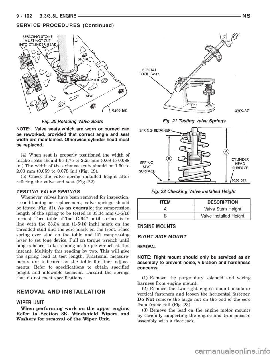
(4) When seat is properly positioned the width of
intake seats should be 1.75 to 2.25 mm (0.69 to 0.088
in.) The width of the exhaust seats should be 1.50 to
2.00 mm (0.059 to 0.078 in.) (Fig. 19).
(5) Check the valve spring installed height after
refacing the valve and seat (Fig. 22).
TESTING VALVE SPRINGS
Whenever valves have been removed for inspection,
reconditioning or replacement, valve springs should
be tested (Fig. 21).As an example;the compression
length of the spring to be tested is 33.34 mm (1-5/16
inches). Turn table of Tool C-647 until surface is in
line with the 33.34 mm (1-5/16 inch) mark on the
threaded stud and the zero mark on the front. Place
spring over stud on the table and lift compressing
lever to set tone device. Pull on torque wrench until
ping is heard. Take reading on torque wrench at this
instant. Multiply this reading by two. This will give
the spring load at test length. Fractional measure-
ments are indicated on the table for finer adjust-
ments. Refer to specifications to obtain specified
height and allowable tensions. Discard the springs
that do not meet specifications.
REMOVAL AND INSTALLATION
WIPER UNIT
When performing work on the upper engine.
Refer to Section 8K, Windshield Wipers and
Washers for removal of the Wiper Unit.
ENGINE MOUNTS
RIGHT SIDE MOUNT
REMOVAL
NOTE: Right mount should only be serviced as an
assembly to prevent noise, vibration and harshness
concerns.
(1) Remove the purge duty solenoid and wiring
harness from engine mount.
(2) Remove the two right engine mount insulator
vertical fasteners and loosen the horizontal fastener,
Do Notremove the large nut on the end of the core
from frame rail (Fig. 23).
(3) Remove the load on the engine motor mounts
by carefully supporting the engine and transmission
assembly with a floor jack.
Fig. 20 Refacing Valve SeatsFig. 21 Testing Valve Springs
Fig. 22 Checking Valve Installed Height
ITEM DESCRIPTION
A Valve Stem Height
B Valve Installed Height
9 - 102 3.3/3.8L ENGINENS
SERVICE PROCEDURES (Continued)
Page 1165 of 1938
PISTON AND CONNECTING ROD
REMOVAL
(1) Disconnect negative cable from battery.
(2) Remove cylinder heads and oil pan. Refer to
procedure outlined in this section.
(3) Remove top ridge of cylinder bores with a reli-
able ridge reamer before removing pistons from cyl-
inder block.Be sure to keep tops of pistons
covered during this operation. Pistons and con-
necting rods must be removed from top of cyl-
inder block. When removing piston and
connecting rod assemblies from the engine,
rotate crankshaft so that each connecting rod
is centered in cylinder bore.
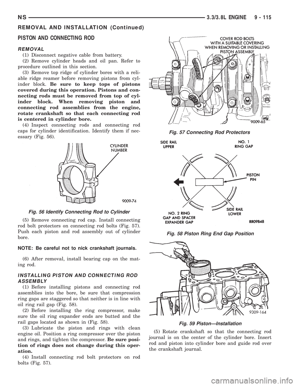
(4) Inspect connecting rods and connecting rod
caps for cylinder identification. Identify them if nec-
essary (Fig. 56).
(5) Remove connecting rod cap. Install connecting
rod bolt protectors on connecting rod bolts (Fig. 57).
Push each piston and rod assembly out of cylinder
bore.
NOTE: Be careful not to nick crankshaft journals.
(6) After removal, install bearing cap on the mat-
ing rod.
INSTALLING PISTON AND CONNECTING ROD
ASSEMBLY
(1) Before installing pistons and connecting rod
assemblies into the bore, be sure that compression
ring gaps are staggered so that neither is in line with
oil ring rail gap (Fig. 58).
(2) Before installing the ring compressor, make
sure the oil ring expander ends are butted and the
rail gaps located as shown in (Fig. 58).
(3) Lubricate the piston and rings with clean
engine oil. Position a ring compressor over the piston
and rings, and tighten the compressor.Be sure posi-
tion of rings does not change during this oper-
ation.
(4) Install connecting rod bolt protectors on rod
bolts (Fig. 57).(5) Rotate crankshaft so that the connecting rod
journal is on the center of the cylinder bore. Insert
rod and piston into cylinder bore and guide rod over
the crankshaft journal.
Fig. 56 Identify Connecting Rod to Cylinder
Fig. 57 Connecting Rod Protectors
Fig. 58 Piston Ring End Gap Position
Fig. 59 PistonÐInstallation
NS3.3/3.8L ENGINE 9 - 115
REMOVAL AND INSTALLATION (Continued)
Page 1173 of 1938
ADJUSTMENTS
ENGINE MOUNTS
ENGINE MOUNT INSULATOR ADJUSTMENT
(1) Remove the load on the engine motor mounts
by carefully supporting the engine and transmission
assembly with a floor jack.
(2) Loosen the right engine mount insulator verti-
cal fastener and the fore and aft fasteners, and the
front engine mount bracket to front crossmember
screws.
(3) Pry the engine right or left as required to
achieve the proper drive shaft assembly length. Refer
to Group 2, Suspension and Driveshafts for drive-
shaft identification and related assembly length mea-
suring.
(4) Tighten engine mounts and fasteners in the
following order:
(a) Right engine mount insulator vertical bolts
to 102 N´m (75 ft. lbs.) and the fore and aft bolts to
150 N´m (110 ft. lbs.).
(b) Front engine mount screws to 54 N´m (40 ft.
lbs.) the clearance between the snubbers and the
engine should be 2 mm (0.078 inch.) each side.
(c) Left engine mount through bolt to 75 N´m (55
ft. lbs.).
(5) Recheck driveshaft length.
SPECIFICATIONS
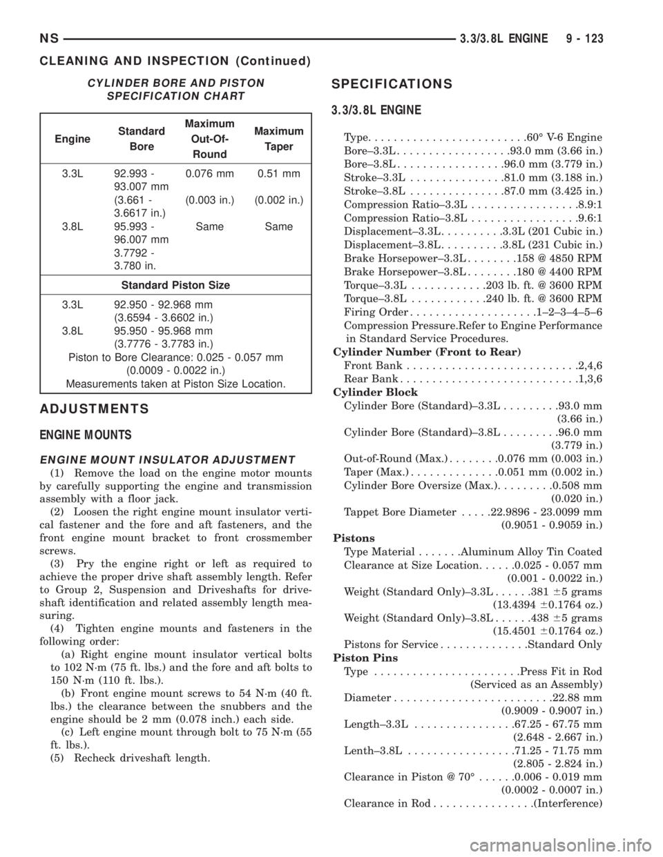
3.3/3.8L ENGINE
Type.........................60É V-6 Engine
Bore±3.3L..................93.0 mm (3.66 in.)
Bore±3.8L.................96.0 mm (3.779 in.)
Stroke±3.3L...............81.0 mm (3.188 in.)
Stroke±3.8L...............87.0 mm (3.425 in.)
Compression Ratio±3.3L.................8.9:1
Compression Ratio±3.8L.................9.6:1
Displacement±3.3L..........3.3L (201 Cubic in.)
Displacement±3.8L..........3.8L (231 Cubic in.)
Brake Horsepower±3.3L........158 @ 4850 RPM
Brake Horsepower±3.8L........180 @ 4400 RPM
Torque±3.3L............203 lb. ft. @ 3600 RPM
Torque±3.8L............240 lb. ft. @ 3600 RPM
Firing Order....................1±2±3±4±5±6
Compression Pressure.Refer to Engine Performance
in Standard Service Procedures.
Cylinder Number (Front to Rear)
Front Bank...........................2,4,6
Rear Bank............................1,3,6
Cylinder Block
Cylinder Bore (Standard)±3.3L.........93.0 mm
(3.66 in.)
Cylinder Bore (Standard)±3.8L.........96.0 mm
(3.779 in.)
Out-of-Round (Max.)........0.076 mm (0.003 in.)
Taper (Max.)..............0.051 mm (0.002 in.)
Cylinder Bore Oversize (Max.).........0.508 mm
(0.020 in.)
Tappet Bore Diameter.....22.9896 - 23.0099 mm
(0.9051 - 0.9059 in.)
Pistons
Type Material.......Aluminum Alloy Tin Coated
Clearance at Size Location......0.025 - 0.057 mm
(0.001 - 0.0022 in.)
Weight (Standard Only)±3.3L......38165 grams
(13.439460.1764 oz.)
Weight (Standard Only)±3.8L......43865 grams
(15.450160.1764 oz.)
Pistons for Service..............Standard Only
Piston Pins
Type .......................Press Fit in Rod
(Serviced as an Assembly)
Diameter.........................22.88 mm
(0.9009 - 0.9007 in.)
Length±3.3L................67.25 - 67.75 mm
(2.648 - 2.667 in.)
Lenth±3.8L.................71.25 - 71.75 mm
(2.805 - 2.824 in.)
Clearance in Piston @ 70É......0.006 - 0.019 mm
(0.0002 - 0.0007 in.)
Clearance in Rod................(Interference)
CYLINDER BORE AND PISTON
SPECIFICATION CHART
EngineStandard
BoreMaximum
Out-Of-
RoundMaximum
Taper
3.3L 92.993 -
93.007 mm0.076 mm 0.51 mm
(3.661 -
3.6617 in.)(0.003 in.) (0.002 in.)
3.8L 95.993 -
96.007 mmSame Same
3.7792 -
3.780 in.
Standard Piston Size
3.3L 92.950 - 92.968 mm
(3.6594 - 3.6602 in.)
3.8L 95.950 - 95.968 mm
(3.7776 - 3.7783 in.)
Piston to Bore Clearance: 0.025 - 0.057 mm
(0.0009 - 0.0022 in.)
Measurements taken at Piston Size Location.
NS3.3/3.8L ENGINE 9 - 123
CLEANING AND INSPECTION (Continued)
Page 1174 of 1938
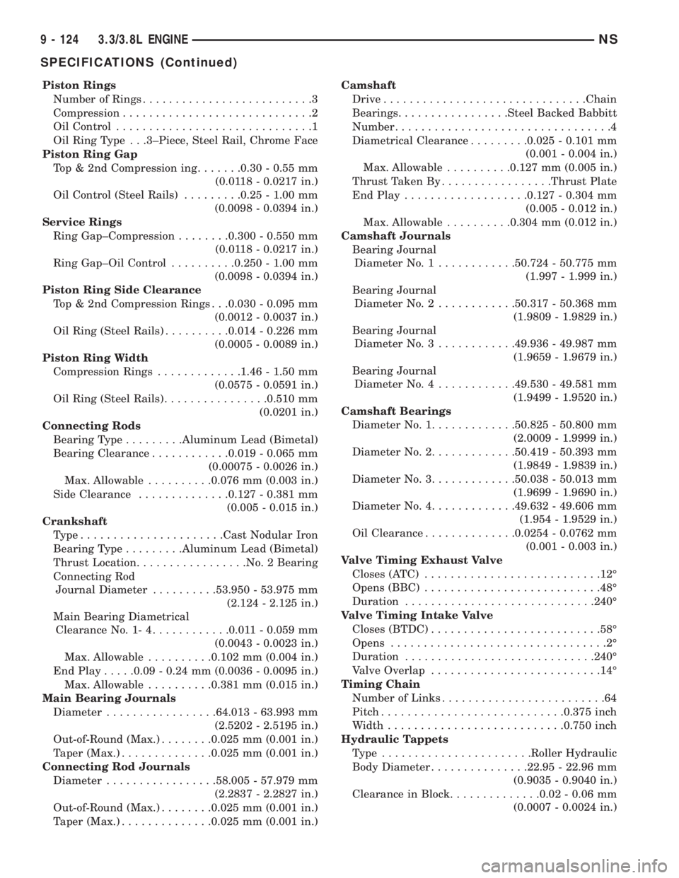
Piston Rings
Number of Rings..........................3
Compression.............................2
Oil Control..............................1
Oil Ring Type . . .3±Piece, Steel Rail, Chrome Face
Piston Ring Gap
Top & 2nd Compression ing.......0.30 - 0.55 mm
(0.0118 - 0.0217 in.)
Oil Control (Steel Rails).........0.25 - 1.00 mm
(0.0098 - 0.0394 in.)
Service Rings
Ring Gap±Compression........0.300 - 0.550 mm
(0.0118 - 0.0217 in.)
Ring Gap±Oil Control..........0.250 - 1.00 mm
(0.0098 - 0.0394 in.)
Piston Ring Side Clearance
Top & 2nd Compression Rings . . .0.030 - 0.095 mm
(0.0012 - 0.0037 in.)
Oil Ring (Steel Rails)..........0.014 - 0.226 mm
(0.0005 - 0.0089 in.)
Piston Ring Width
Compression Rings.............1.46 - 1.50 mm
(0.0575 - 0.0591 in.)
Oil Ring (Steel Rails)................0.510 mm
(0.0201 in.)
Connecting Rods
Bearing Type.........Aluminum Lead (Bimetal)
Bearing Clearance............0.019 - 0.065 mm
(0.00075 - 0.0026 in.)
Max. Allowable..........0.076 mm (0.003 in.)
Side Clearance..............0.127 - 0.381 mm
(0.005 - 0.015 in.)
Crankshaft
Type......................Cast Nodular Iron
Bearing Type.........Aluminum Lead (Bimetal)
Thrust Location.................No. 2 Bearing
Connecting Rod
Journal Diameter..........53.950 - 53.975 mm
(2.124 - 2.125 in.)
Main Bearing Diametrical
Clearance No. 1- 4............0.011 - 0.059 mm
(0.0043 - 0.0023 in.)
Max. Allowable..........0.102 mm (0.004 in.)
End Play.....0.09 - 0.24 mm (0.0036 - 0.0095 in.)
Max. Allowable..........0.381 mm (0.015 in.)
Main Bearing Journals
Diameter.................64.013 - 63.993 mm
(2.5202 - 2.5195 in.)
Out-of-Round (Max.)........0.025 mm (0.001 in.)
Taper (Max.)..............0.025 mm (0.001 in.)
Connecting Rod Journals
Diameter.................58.005 - 57.979 mm
(2.2837 - 2.2827 in.)
Out-of-Round (Max.)........0.025 mm (0.001 in.)
Taper (Max.)..............0.025 mm (0.001 in.)Camshaft
Drive...............................Chain
Bearings.................Steel Backed Babbitt
Number.................................4
Diametrical Clearance.........0.025 - 0.101 mm
(0.001 - 0.004 in.)
Max. Allowable..........0.127 mm (0.005 in.)
Thrust Taken By.................Thrust Plate
End Play...................0.127 - 0.304 mm
(0.005 - 0.012 in.)
Max. Allowable..........0.304 mm (0.012 in.)
Camshaft Journals
Bearing Journal
Diameter No. 1............50.724 - 50.775 mm
(1.997 - 1.999 in.)
Bearing Journal
Diameter No. 2............50.317 - 50.368 mm
(1.9809 - 1.9829 in.)
Bearing Journal
Diameter No. 3............49.936 - 49.987 mm
(1.9659 - 1.9679 in.)
Bearing Journal
Diameter No. 4............49.530 - 49.581 mm
(1.9499 - 1.9520 in.)
Camshaft Bearings
Diameter No. 1.............50.825 - 50.800 mm
(2.0009 - 1.9999 in.)
Diameter No. 2.............50.419 - 50.393 mm
(1.9849 - 1.9839 in.)
Diameter No. 3.............50.038 - 50.013 mm
(1.9699 - 1.9690 in.)
Diameter No. 4.............49.632 - 49.606 mm
(1.954 - 1.9529 in.)
Oil Clearance..............0.0254 - 0.0762 mm
(0.001 - 0.003 in.)
Valve Timing Exhaust Valve
Closes (ATC)...........................12É
Opens (BBC)...........................48É
Duration.............................240É
Valve Timing Intake Valve
Closes (BTDC)..........................58É
Opens.................................2É
Duration.............................240É
Valve Overlap..........................14É
Timing Chain
Number of Links.........................64
Pitch............................0.375 inch
Width...........................0.750 inch
Hydraulic Tappets
Type .......................Roller Hydraulic
Body Diameter...............22.95 - 22.96 mm
(0.9035 - 0.9040 in.)
Clearance in Block..............0.02 - 0.06 mm
(0.0007 - 0.0024 in.)
9 - 124 3.3/3.8L ENGINENS
SPECIFICATIONS (Continued)
Page 1180 of 1938
GENERAL SPECIFICATION
Type .............In-Line OHV, DOHC & SOHC
Bore.....................87.5mm (3.445 Inch)
Stroke...................83.0mm (3.268 inch)
Compression Ratio....DOHC - 9.6:1 SOHC - 9.8:1
Displacement.........2.0Liters (122 Cubic Inch)
Firing Order........................1,3,4,2
Compression Pressure...........1172-1551 kPa
(170 - 225 psi)
Maximum Variation Between Cylinders......25%
Lubrication . . . Pressure Feed - Full Flow Filtration
(Crankshaft Driven Pump)
Engine Oil Capacity . . Refer to Group 0, Lubrication
and Maintenance
ENGINE LUBRICATION SYSTEM
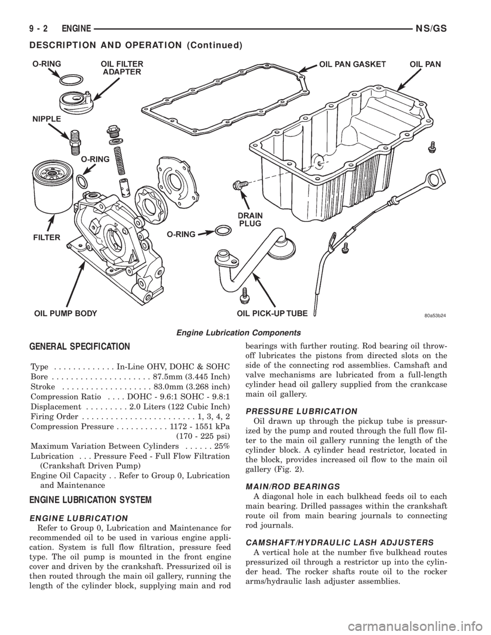
ENGINE LUBRICATION
Refer to Group 0, Lubrication and Maintenance for
recommended oil to be used in various engine appli-
cation. System is full flow filtration, pressure feed
type. The oil pump is mounted in the front engine
cover and driven by the crankshaft. Pressurized oil is
then routed through the main oil gallery, running the
length of the cylinder block, supplying main and rodbearings with further routing. Rod bearing oil throw-
off lubricates the pistons from directed slots on the
side of the connecting rod assemblies. Camshaft and
valve mechanisms are lubricated from a full-length
cylinder head oil gallery supplied from the crankcase
main oil gallery.
PRESSURE LUBRICATION
Oil drawn up through the pickup tube is pressur-
ized by the pump and routed through the full flow fil-
ter to the main oil gallery running the length of the
cylinder block. A cylinder head restrictor, located in
the block, provides increased oil flow to the main oil
gallery (Fig. 2).
MAIN/ROD BEARINGS
A diagonal hole in each bulkhead feeds oil to each
main bearing. Drilled passages within the crankshaft
route oil from main bearing journals to connecting
rod journals.
CAMSHAFT/HYDRAULIC LASH ADJUSTERS
A vertical hole at the number five bulkhead routes
pressurized oil through a restrictor up into the cylin-
der head. The rocker shafts route oil to the rocker
arms/hydraulic lash adjuster assemblies.
Engine Lubrication Components
9 - 2 ENGINENS/GS
DESCRIPTION AND OPERATION (Continued)
Page 1181 of 1938
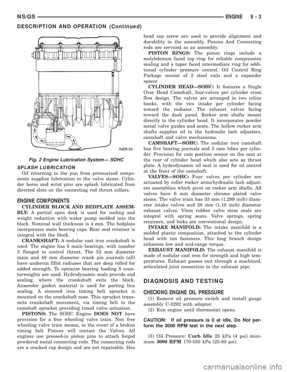
SPLASH LUBRICATION
Oil returning to the pan from pressurized compo-
nents supplies lubrication to the valve stems. Cylin-
der bores and wrist pins are splash lubricated from
directed slots on the connecting rod thrust collars.
ENGINE COMPONENTS
CYLINDER BLOCK AND BEDPLATE ASSEM-
B LY:A partial open deck is used for cooling and
weight reduction with water pump molded into the
block. Nominal wall thickness is 4 mm. The bedplate
incorporates main bearing caps. Rear seal retainer is
integral with the block.
CRANKSHAFT:A nodular cast iron crankshaft is
used. The engine has 5 main bearings, with number
3 flanged to control thrust. The 52 mm diameter
main and 48 mm diameter crank pin journals (all)
have undercut fillet radiuses that are deep rolled for
added strength. To optimize bearing loading 8 coun-
terweights are used. Hydrodynamic seals provide end
sealing, where the crankshaft exits the block.
Anaerobic gasket material is used for parting line
sealing. A sintered iron timing belt sprocket is
mounted on the crankshaft nose. This sprocket trans-
mits crankshaft movement, via timing belt to the
camshaft sprocket providing timed valve actuation.
PISTONS:The SOHC EngineDOES NOThave
provision for a free wheeling valve train. Non free
wheeling valve train means, in the event of a broken
timing belt Pistons will contact the Valves. All
engines use pressed-in piston pins to attach forged
powdered metal connecting rods. The connecting rods
are a cracked cap design and are not repairable. Hexhead cap screw are used to provide alignment and
durability in the assembly. Pistons And Connecting
rods are serviced as an assembly.
PISTON RINGS:The piston rings include a
molybdenum faced top ring for reliable compression
sealing and a taper faced intermediate ring for addi-
tional cylinder pressure control. Oil Control Ring
Package consist of 2 steel rails and a expander
spacer.
CYLINDER HEADÐSOHC:It features a Single
Over Head Camshaft, four-valves per cylinder cross
flow design. The valves are arranged in two inline
banks, with the two intake per cylinder facing
toward the radiator. The exhaust valves facing
toward the dash panel. Rocker arm shafts mount
directly to the cylinder head. It incorporates powder
metal valve guides and seats. The hollow rocker arm
shafts supplies oil to the hydraulic lash adjusters,
camshaft and valve mechanisms.
CAMSHAFTÐSOHC:The nodular iron camshaft
has five bearing journals and 3 cam lobes per cylin-
der. Provision for cam position sensor on the cam at
the rear of cylinder head which also acts as thrust
plate. A hydrodynamic oil seal is used for oil control
at the front of the camshaft.
VALVESÐSOHC:Four valves per cylinder are
actuated by roller rocker arms/hydraulic lash adjust-
ers assemblies which pivot on rocker arm shafts. All
valves have 6 mm diameter chrome plated valve
stems. The valve train has 33 mm (1.299 inch) diam-
eter intake valves and 28 mm (1.10 inch) diameter
exhaust valves. Viton rubber valve stem seals are
integral with spring seats. Valve springs, spring
retainers, and locks are conventional design.
INTAKE MANIFOLD:The intake manifold is a
molded plastic composition, attached to the cylinder
head with ten fasteners. This long branch design
enhances low and mid-range torque.
EXHAUST MANIFOLD:The exhaust manifold is
made of nodular cast iron for strength and high tem-
peratures. Exhaust gasses exit through a machined,
articulated joint connection to the exhaust pipe.
DIAGNOSIS AND TESTING
CHECKING ENGINE OIL PRESSURE
(1) Remove oil pressure switch and install gauge
assembly C-3292 with adaptor.
(2) Run engine until thermostat opens.
CAUTION: If oil pressure is 0 at idle, Do Not per-
form the 3000 RPM test in the next step.
(3) Oil Pressure:Curb Idle25 kPa (4 psi) mini-
mum3000 RPM170-550 kPa (25-80 psi).
Fig. 2 Engine Lubrication SystemÐ SOHC
NS/GSENGINE 9 - 3
DESCRIPTION AND OPERATION (Continued)
Page 1206 of 1938
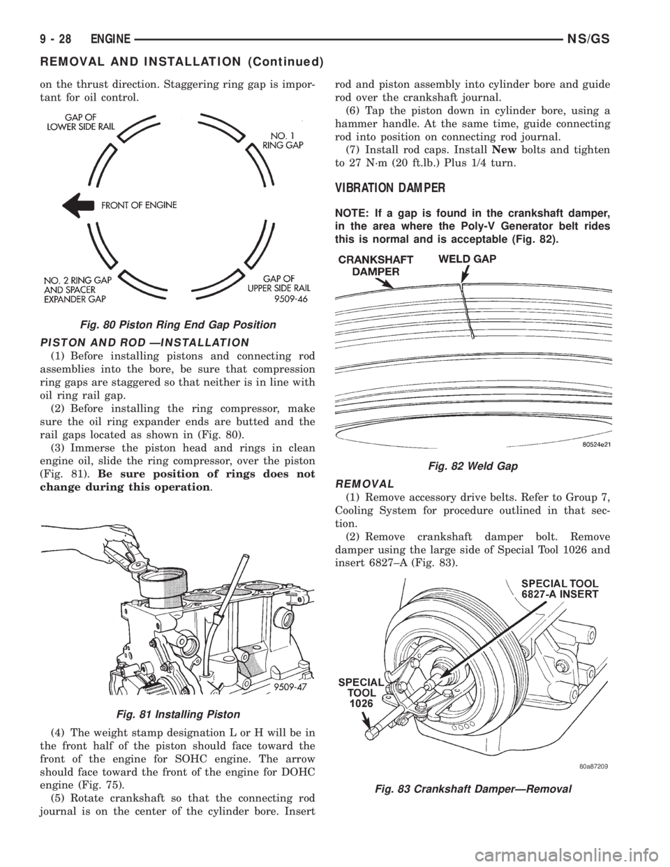
on the thrust direction. Staggering ring gap is impor-
tant for oil control.
PISTON AND ROD ÐINSTALLATION
(1) Before installing pistons and connecting rod
assemblies into the bore, be sure that compression
ring gaps are staggered so that neither is in line with
oil ring rail gap.
(2) Before installing the ring compressor, make
sure the oil ring expander ends are butted and the
rail gaps located as shown in (Fig. 80).
(3) Immerse the piston head and rings in clean
engine oil, slide the ring compressor, over the piston
(Fig. 81).Be sure position of rings does not
change during this operation.
(4) The weight stamp designation L or H will be in
the front half of the piston should face toward the
front of the engine for SOHC engine. The arrow
should face toward the front of the engine for DOHC
engine (Fig. 75).
(5) Rotate crankshaft so that the connecting rod
journal is on the center of the cylinder bore. Insertrod and piston assembly into cylinder bore and guide
rod over the crankshaft journal.
(6) Tap the piston down in cylinder bore, using a
hammer handle. At the same time, guide connecting
rod into position on connecting rod journal.
(7) Install rod caps. InstallNewbolts and tighten
to 27 N´m (20 ft.lb.) Plus 1/4 turn.
VIBRATION DAMPER
NOTE: If a gap is found in the crankshaft damper,
in the area where the Poly-V Generator belt rides
this is normal and is acceptable (Fig. 82).
REMOVAL
(1) Remove accessory drive belts. Refer to Group 7,
Cooling System for procedure outlined in that sec-
tion.
(2) Remove crankshaft damper bolt. Remove
damper using the large side of Special Tool 1026 and
insert 6827±A (Fig. 83).
Fig. 80 Piston Ring End Gap Position
Fig. 81 Installing Piston
Fig. 82 Weld Gap
Fig. 83 Crankshaft DamperÐRemoval
9 - 28 ENGINENS/GS
REMOVAL AND INSTALLATION (Continued)