1996 CHRYSLER VOYAGER ad blue
[x] Cancel search: ad bluePage 939 of 1938

MIRROR - C2 PASSENGER POWER
6 5BLUE4
213
P68 20DG/RD P66 20WT/BK P67 20YL/RD
3 2
1 CAV PASSENGER MIRROR POSITION (HORIZONTAL)
PASSENGER MIRROR POSITION COMMON PASSENGER MIRROR POSITION (VERTICAL) CIRCUIT
FUNCTION
MIRROR - C1 PASSENGER POWER
RED564
1 2 3Z1 20BK C16 20LB/YL P70 20WT P72 20YL/BK
P74 20DB
6 5 4
3
2 1 CAV GROUND FUSED B(+) MIRROR SWITCH COMMON
MIRROR SWITCH OUTPUT (VERTICAL) MIRROR SWITCH OUTPUT (HORIZONTAL)
- CIRCUIT
- FUNCTION
4
--
5
P159 20DG* PASSENGER MIRROR UNFOLD SIGNAL
6
P160 20LB* PASSENGER MIRROR FOLD SIGNAL
* BUILT-UP-EXPORT FUSED IGNITION (RUN)-
DSEAT SWITCH PASSENGER HEATEDC B A
F20 20WT- F20 20WT P86 20VT CAV
FUSED IGNITION (RUN) HEATED SEAT TEMPERATURE SENSOR CIRCUIT FUNCTION
Z1 18BK EGROUND
F
P8 20WT/BKPASSENGER HEATED SEAT SWITCH
** RKE
NS/GS8W-80 CONNECTOR PIN-OUTS 8W - 80 - 63
NSGS8063J988W-3
Page 1072 of 1938
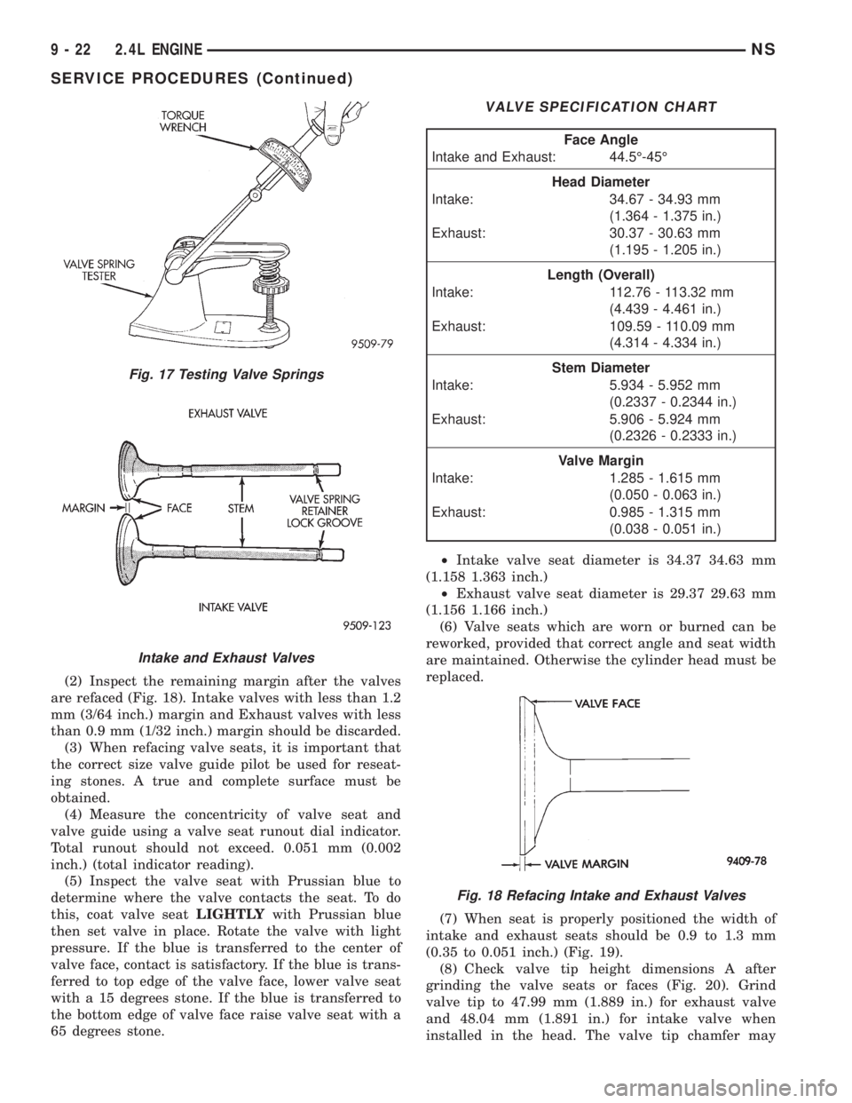
(2) Inspect the remaining margin after the valves
are refaced (Fig. 18). Intake valves with less than 1.2
mm (3/64 inch.) margin and Exhaust valves with less
than 0.9 mm (1/32 inch.) margin should be discarded.
(3) When refacing valve seats, it is important that
the correct size valve guide pilot be used for reseat-
ing stones. A true and complete surface must be
obtained.
(4) Measure the concentricity of valve seat and
valve guide using a valve seat runout dial indicator.
Total runout should not exceed. 0.051 mm (0.002
inch.) (total indicator reading).
(5) Inspect the valve seat with Prussian blue to
determine where the valve contacts the seat. To do
this, coat valve seatLIGHTLYwith Prussian blue
then set valve in place. Rotate the valve with light
pressure. If the blue is transferred to the center of
valve face, contact is satisfactory. If the blue is trans-
ferred to top edge of the valve face, lower valve seat
with a 15 degrees stone. If the blue is transferred to
the bottom edge of valve face raise valve seat with a
65 degrees stone.²Intake valve seat diameter is 34.37 34.63 mm
(1.158 1.363 inch.)
²Exhaust valve seat diameter is 29.37 29.63 mm
(1.156 1.166 inch.)
(6) Valve seats which are worn or burned can be
reworked, provided that correct angle and seat width
are maintained. Otherwise the cylinder head must be
replaced.
(7) When seat is properly positioned the width of
intake and exhaust seats should be 0.9 to 1.3 mm
(0.35 to 0.051 inch.) (Fig. 19).
(8) Check valve tip height dimensions A after
grinding the valve seats or faces (Fig. 20). Grind
valve tip to 47.99 mm (1.889 in.) for exhaust valve
and 48.04 mm (1.891 in.) for intake valve when
installed in the head. The valve tip chamfer may
Fig. 17 Testing Valve Springs
Intake and Exhaust Valves
VALVE SPECIFICATION CHART
Face Angle
Intake and Exhaust: 44.5É-45É
Head Diameter
Intake: 34.67 - 34.93 mm
(1.364 - 1.375 in.)
Exhaust: 30.37 - 30.63 mm
(1.195 - 1.205 in.)
Length (Overall)
Intake: 112.76 - 113.32 mm
(4.439 - 4.461 in.)
Exhaust: 109.59 - 110.09 mm
(4.314 - 4.334 in.)
Stem Diameter
Intake: 5.934 - 5.952 mm
(0.2337 - 0.2344 in.)
Exhaust: 5.906 - 5.924 mm
(0.2326 - 0.2333 in.)
Valve Margin
Intake: 1.285 - 1.615 mm
(0.050 - 0.063 in.)
Exhaust: 0.985 - 1.315 mm
(0.038 - 0.051 in.)
Fig. 18 Refacing Intake and Exhaust Valves
9 - 22 2.4L ENGINENS
SERVICE PROCEDURES (Continued)
Page 1117 of 1938
VALVE SEAT
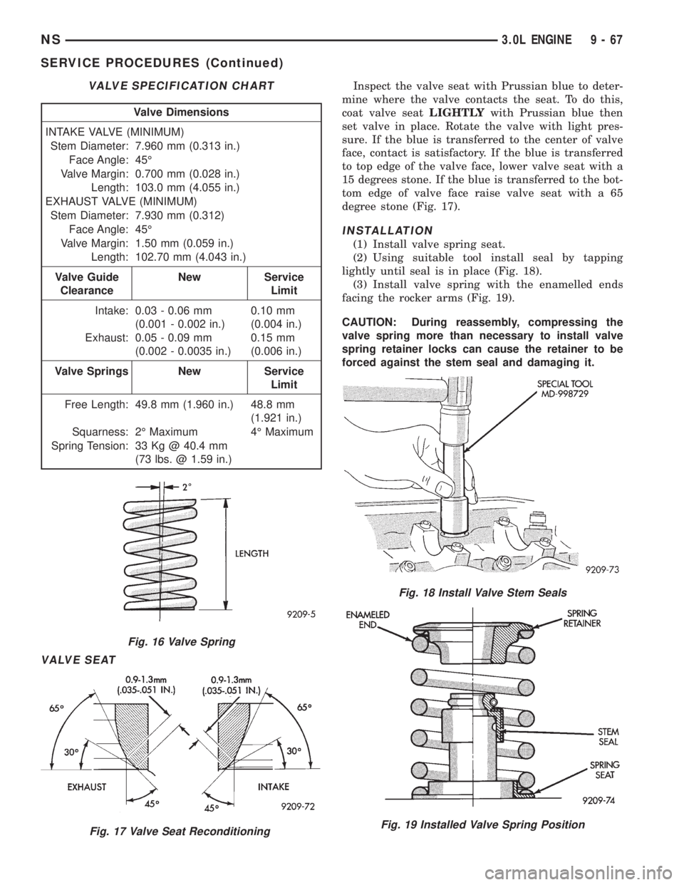
Inspect the valve seat with Prussian blue to deter-
mine where the valve contacts the seat. To do this,
coat valve seatLIGHTLYwith Prussian blue then
set valve in place. Rotate the valve with light pres-
sure. If the blue is transferred to the center of valve
face, contact is satisfactory. If the blue is transferred
to top edge of the valve face, lower valve seat with a
15 degrees stone. If the blue is transferred to the bot-
tom edge of valve face raise valve seat with a 65
degree stone (Fig. 17).
INSTALLATION
(1) Install valve spring seat.
(2) Using suitable tool install seal by tapping
lightly until seal is in place (Fig. 18).
(3) Install valve spring with the enamelled ends
facing the rocker arms (Fig. 19).
CAUTION: During reassembly, compressing the
valve spring more than necessary to install valve
spring retainer locks can cause the retainer to be
forced against the stem seal and damaging it.
VALVE SPECIFICATION CHART
Valve Dimensions
INTAKE VALVE (MINIMUM)
Stem Diameter: 7.960 mm (0.313 in.)
Face Angle: 45É
Valve Margin: 0.700 mm (0.028 in.)
Length: 103.0 mm (4.055 in.)
EXHAUST VALVE (MINIMUM)
Stem Diameter: 7.930 mm (0.312)
Face Angle: 45É
Valve Margin: 1.50 mm (0.059 in.)
Length: 102.70 mm (4.043 in.)
Valve Guide
ClearanceNew Service
Limit
Intake: 0.03 - 0.06 mm
(0.001 - 0.002 in.)0.10 mm
(0.004 in.)
Exhaust: 0.05 - 0.09 mm
(0.002 - 0.0035 in.)0.15 mm
(0.006 in.)
Valve Springs New Service
Limit
Free Length: 49.8 mm (1.960 in.) 48.8 mm
(1.921 in.)
Squarness: 2É Maximum 4É Maximum
Spring Tension: 33 Kg @ 40.4 mm
(73 lbs. @ 1.59 in.)
Fig. 16 Valve Spring
Fig. 17 Valve Seat Reconditioning
Fig. 18 Install Valve Stem Seals
Fig. 19 Installed Valve Spring Position
NS3.0L ENGINE 9 - 67
SERVICE PROCEDURES (Continued)
Page 1151 of 1938
dure of 0.15 mm (0.005 in.), 0.40 mm (0.015 in.)
and 0.80 mm (0.030 in.) so the valve guides may
be reamed true in relation to the valve seat.
After reaming guides, the seat runout should be
measured and resurfaced if necessary. See
Refacing Valves and Valve Seats.VALVE GUIDES
NOTE: Replace cylinder head if guide does not
clean up with 0.80 mm (0.030 in.) oversize reamer,
or if guide is loose in cylinder head.
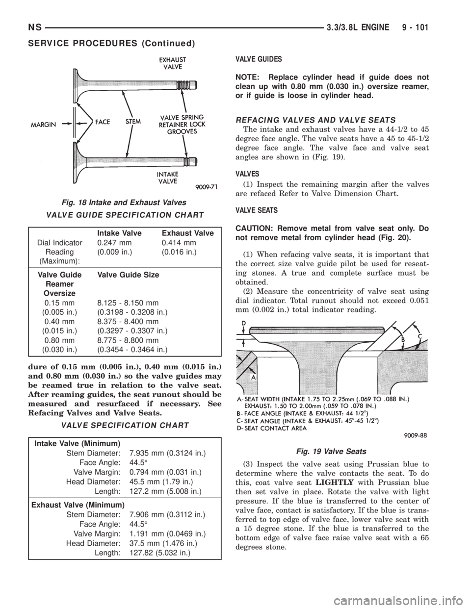
REFACING VALVES AND VALVE SEATS
The intake and exhaust valves have a 44-1/2 to 45
degree face angle. The valve seats have a 45 to 45-1/2
degree face angle. The valve face and valve seat
angles are shown in (Fig. 19).
VALVES
(1) Inspect the remaining margin after the valves
are refaced Refer to Valve Dimension Chart.
VALVE SEATS
CAUTION: Remove metal from valve seat only. Do
not remove metal from cylinder head (Fig. 20).
(1) When refacing valve seats, it is important that
the correct size valve guide pilot be used for reseat-
ing stones. A true and complete surface must be
obtained.
(2) Measure the concentricity of valve seat using
dial indicator. Total runout should not exceed 0.051
mm (0.002 in.) total indicator reading.
(3) Inspect the valve seat using Prussian blue to
determine where the valve contacts the seat. To do
this, coat valve seatLIGHTLYwith Prussian blue
then set valve in place. Rotate the valve with light
pressure. If the blue is transferred to the center of
valve face, contact is satisfactory. If the blue is trans-
ferred to top edge of valve face, lower valve seat with
a 15 degree stone. If the blue is transferred to the
bottom edge of valve face raise valve seat with a 65
degrees stone.
Fig. 18 Intake and Exhaust Valves
VALVE GUIDE SPECIFICATION CHART
Intake Valve Exhaust Valve
Dial Indicator
Reading
(Maximum):0.247 mm
(0.009 in.)0.414 mm
(0.016 in.)
Valve Guide
Reamer
OversizeValve Guide Size
0.15 mm
(0.005 in.)8.125 - 8.150 mm
(0.3198 - 0.3208 in.)
0.40 mm
(0.015 in.)8.375 - 8.400 mm
(0.3297 - 0.3307 in.)
0.80 mm
(0.030 in.)8.775 - 8.800 mm
(0.3454 - 0.3464 in.)
VALVE SPECIFICATION CHART
Intake Valve (Minimum)
Stem Diameter: 7.935 mm (0.3124 in.)
Face Angle: 44.5É
Valve Margin: 0.794 mm (0.031 in.)
Head Diameter: 45.5 mm (1.79 in.)
Length: 127.2 mm (5.008 in.)
Exhaust Valve (Minimum)
Stem Diameter: 7.906 mm (0.3112 in.)
Face Angle: 44.5É
Valve Margin: 1.191 mm (0.0469 in.)
Head Diameter: 37.5 mm (1.476 in.)
Length: 127.82 (5.032 in.)
Fig. 19 Valve Seats
NS3.3/3.8L ENGINE 9 - 101
SERVICE PROCEDURES (Continued)
Page 1209 of 1938
Total runout should not exceed. 0.051 mm (0.002
inch.) (total indicator reading).
(5) Inspect the valve seat with Prussian blue to
determine where the valve contacts the seat. To do
this, coat valve seatLIGHTLYwith Prussian blue
then set valve in place. Rotate the valve with light
pressure. If the blue is transferred to the center of
valve face, contact is satisfactory. If the blue is trans-
ferred to top edge of the valve face, lower valve seat
with a 15 degrees stone. If the blue is transferred to
the bottom edge of valve face raise valve seat with a
65 degrees stone.
²Intake valve seat diameter is 33 mm (1.299 in.)
²Exhaust valve seat diameter is 28 mm (1.102
in.)
(6) Valve seats which are worn or burned can be
reworked, provided that correct angle and seat width
are maintained. The intake valve seat must be ser-
viced when the valve seat width is 2.0 mm (0.079 in.)
or greater. The exhaust valve seat must be serviced
when the valve seat width is 2.5 mm (0.098 in.) or
greater. Otherwise the cylinder head must be
replaced.
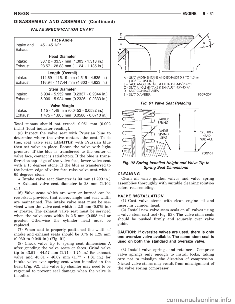
(7) When seat is properly positioned the width of
intake and exhaust seats should be 0.75 to 1.25 mm
(0.030 to 0.049 in.) (Fig. 91).
(8) Check valve tip to spring seat dimensions A
after grinding the valve seats or faces. Grind valve
tip to 43.51 - 44.57 mm (1.71 - 1.75 in.) for exhaust
valve and 45.01 - 46.07 mm (1.77 - 1.81 in.) for
intake valve over spring seat when installed in the
head (Fig. 92). The valve tip chamfer may need to be
reground to prevent seal damage when the valve is
installed.
CLEANING
Clean all valve guides, valves and valve spring
assemblies thoroughly with suitable cleaning solution
before reassembling.
VALVE INSTALLATION
(1) Coat valve stems with clean engine oil and
insert in cylinder head.
(2) Install new valve stem seals on all valves using
a valve stem seal tool (Fig. 93). The valve stem seals
should be pushed firmly and squarely over valve
guide.
CAUTION: If oversize valves are used, there is only
one oversize valve available. The same stem seal is
used on both the standard and oversize valve.
(3) Install valve springs and retainers. Compress
valve springs only enough to install locks, taking
care not to misalign the direction of compression.
Nicked valve stems may result from misalignment of
the valve spring compressor.
VALVE SPECIFICATION CHART
Face Angle
Intake and
Exhaust:45 - 45 1/2É
Head Diameter
Intake: 33.12 - 33.37 mm (1.303 - 1.313 in.)
Exhaust: 28.57 - 28.83 mm (1.124 - 1.135 in.)
Length (Overall)
Intake: 114.69 - 115.19 mm (4.515 - 4.535 in.)
Exhaust: 116.94 - 117.44 mm (4.603 - 4.623 in.)
Stem Diameter
Intake: 5.934 - 5.952 mm (0.2337 - 0.2344 in.)
Exhaust: 5.906 - 5.924 mm (0.2326 - 0.2333 in.)
Valve Margin
Intake: 1.15 - 1.48 mm (0.0452 - 0.0582 in.)
Exhaust: 1.475 - 1.805 mm (0.0580 - 0.0710 in.)
Fig. 91 Valve Seat Refacing
Fig. 92 Spring Installed Height and Valve Tip to
Spring Seat Dimensions
NS/GSENGINE 9 - 31
DISASSEMBLY AND ASSEMBLY (Continued)
Page 1309 of 1938
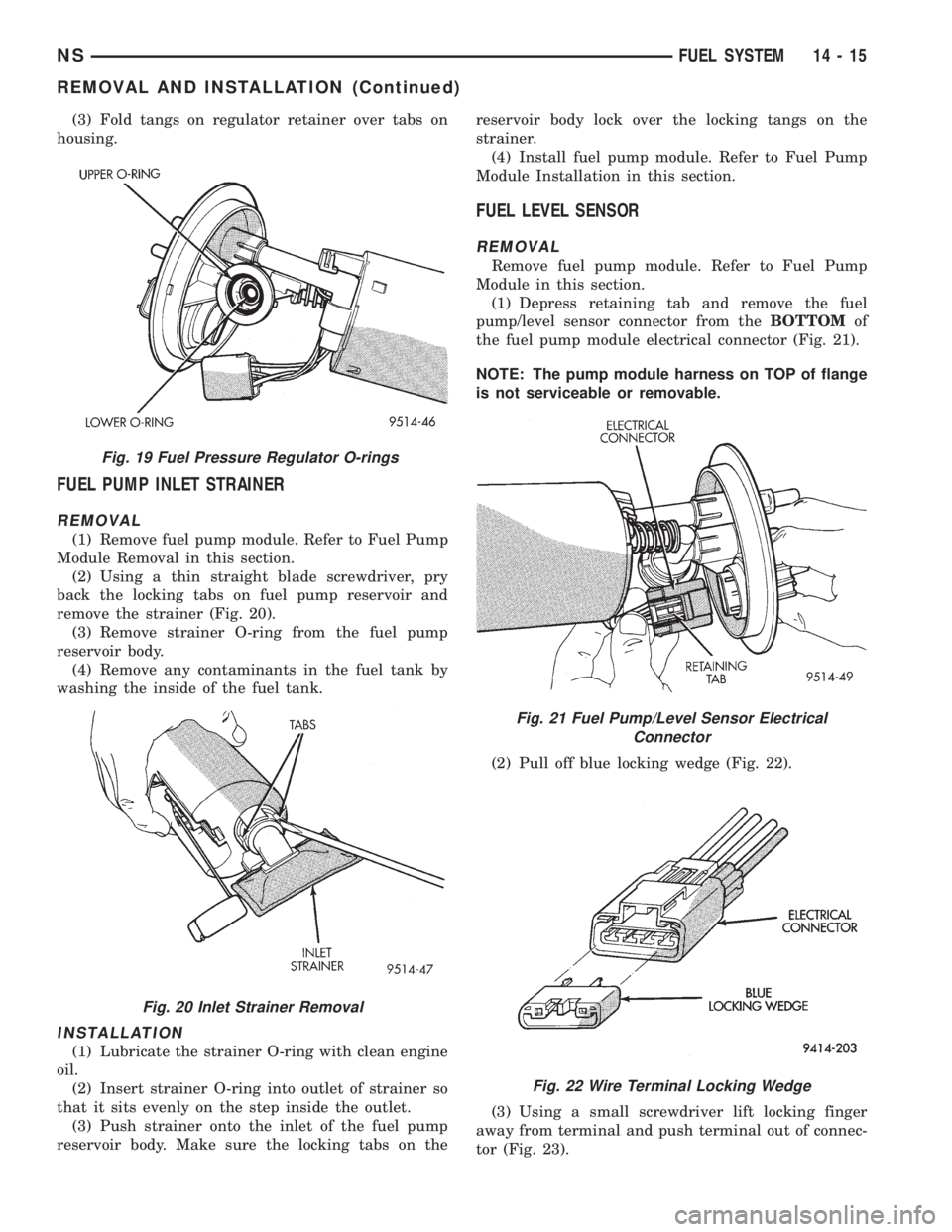
(3) Fold tangs on regulator retainer over tabs on
housing.
FUEL PUMP INLET STRAINER
REMOVAL
(1) Remove fuel pump module. Refer to Fuel Pump
Module Removal in this section.
(2) Using a thin straight blade screwdriver, pry
back the locking tabs on fuel pump reservoir and
remove the strainer (Fig. 20).
(3) Remove strainer O-ring from the fuel pump
reservoir body.
(4) Remove any contaminants in the fuel tank by
washing the inside of the fuel tank.
INSTALLATION
(1) Lubricate the strainer O-ring with clean engine
oil.
(2) Insert strainer O-ring into outlet of strainer so
that it sits evenly on the step inside the outlet.
(3) Push strainer onto the inlet of the fuel pump
reservoir body. Make sure the locking tabs on thereservoir body lock over the locking tangs on the
strainer.
(4) Install fuel pump module. Refer to Fuel Pump
Module Installation in this section.
FUEL LEVEL SENSOR
REMOVAL
Remove fuel pump module. Refer to Fuel Pump
Module in this section.
(1) Depress retaining tab and remove the fuel
pump/level sensor connector from theBOTTOMof
the fuel pump module electrical connector (Fig. 21).
NOTE: The pump module harness on TOP of flange
is not serviceable or removable.
(2) Pull off blue locking wedge (Fig. 22).
(3) Using a small screwdriver lift locking finger
away from terminal and push terminal out of connec-
tor (Fig. 23).
Fig. 19 Fuel Pressure Regulator O-rings
Fig. 20 Inlet Strainer Removal
Fig. 21 Fuel Pump/Level Sensor Electrical
Connector
Fig. 22 Wire Terminal Locking Wedge
NSFUEL SYSTEM 14 - 15
REMOVAL AND INSTALLATION (Continued)
Page 1381 of 1938
A defective fuel injection pump, defective fuel tim-
ing solenoid or misadjusted mechanical pump timing
can cause starting problems or prevent the engine
from revving up. It can also cause:
²Engine surge at idle
²Rough idle (warm engine)
²Low power
²Excessive fuel consumption
²Poor performance
²Low power
²Black smoke from the exhaust
²Blue or white fog like exhaust
²Incorrect idle or maximum speed
The electronically controlled fuel pump has no
mechanical governor like older mechanically con-
trolled fuel pumps. Do not remove the top cover of
the fuel pump, or the screws fastening the wiring
pigtail to the side of the pump.The warranty of
the injection pump and the engine may be void
if those seals have been removed or tampered
with.
FUEL SUPPLY RESTRICTIONS
LOW±PRESSURE LINES
Restricted or Plugged supply lines or fuel filter can
cause a timing fault that will cause the PCM to oper-
ate the engine in a ªLimp Homeº mode. See the
introduction of the Fuel Injection System in this
group for more information on the Limp Home mode.
Fuel supply line restrictions can cause starting prob-
lems and prevent the engine from revving up. The
starting problems include; low power and blue or
white fog like exhaust. Test all fuel supply lines for
restrictions or blockage. Flush or replace as neces-
sary. Bleed the fuel system of air once a fuel supply
line has been replaced. Refer to the Air Bleed Proce-
dure section of this group for procedures.
HIGH±PRESSURE LINES
Restricted (kinked or bent) high±pressure lines can
cause starting problems, poor engine performance
and black smoke from exhaust.
Examine all high±pressure lines for any damage.
Each radius on each high±pressure line must be
smooth and free of any bends or kinks.
Replace damaged, restricted or leaking high±pres-
sure fuel lines with the correct replacement line.
CAUTION: The high±pressure fuel lines must be
clamped securely in place in the holders. The lines
cannot contact each other or other components. Do
not attempt to weld high±pressure fuel lines or to
repair lines that are damaged. Only use the recom-
mended lines when replacement of high±pressure
fuel line is necessary.
FUEL SHUTDOWN SOLENOID TEST
Since diesel fuel injection does not use spark plugs
to start combustion, the only way to stop the engine
is to cut off the fuel supply. This is done with the
Fuel Shutdown Solenoid. If the engine cranks, but
refuses to start, it may be caused by a defective fuel
shutdown solenoid.
The fuel shutdown solenoid is not controlled
or operated by the PCM.Voltage to operate the
solenoid is supplied from the ignition (key) switch.
NOTE: Although the fuel shutdown solenoid is not
operated by the PCM, if the Fuel Shutdown Solenoid
has been disconnected, and the key turned on, the
PCM will sense that the solenoid is not in the circuit,
and will switch to a ªLimp Homeº mode. After recon-
necting the solenoid, the PCM will have to be reset
by clearing the codes with the DRBIII scan tool, or
disconnecting the vehicle's battery for several min-
utes. The DRBIII scan tool is the preferred method
for resetting the PCM. Refer to the 1998 GS 2.5L Die-
sel Powertrain Diagnostic Manual for procedure.
The fuel shutdown (shut±off) solenoid is used to
electrically shut off the diesel fuel supply to the high-
±pressure fuel injection pump. The solenoid is
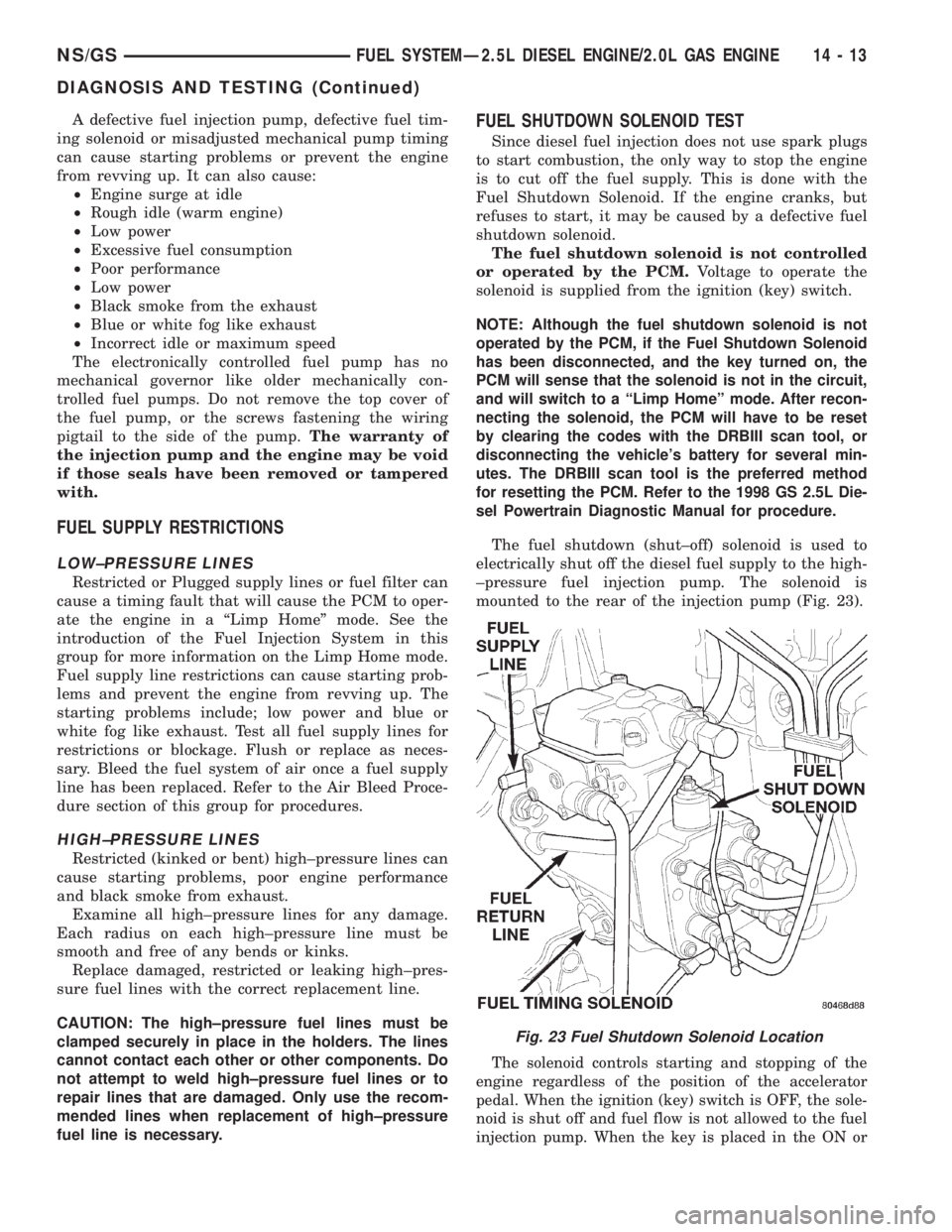
mounted to the rear of the injection pump (Fig. 23).
The solenoid controls starting and stopping of the
engine regardless of the position of the accelerator
pedal. When the ignition (key) switch is OFF, the sole-
noid is shut off and fuel flow is not allowed to the fuel
injection pump. When the key is placed in the ON or
Fig. 23 Fuel Shutdown Solenoid Location
NS/GSFUEL SYSTEMÐ2.5L DIESEL ENGINE/2.0L GAS ENGINE 14 - 13
DIAGNOSIS AND TESTING (Continued)
Page 1386 of 1938
FUEL LEVEL SENSOR
REMOVAL
Remove fuel reservoir module. Refer to Fuel Reser-
voir Module in this section.
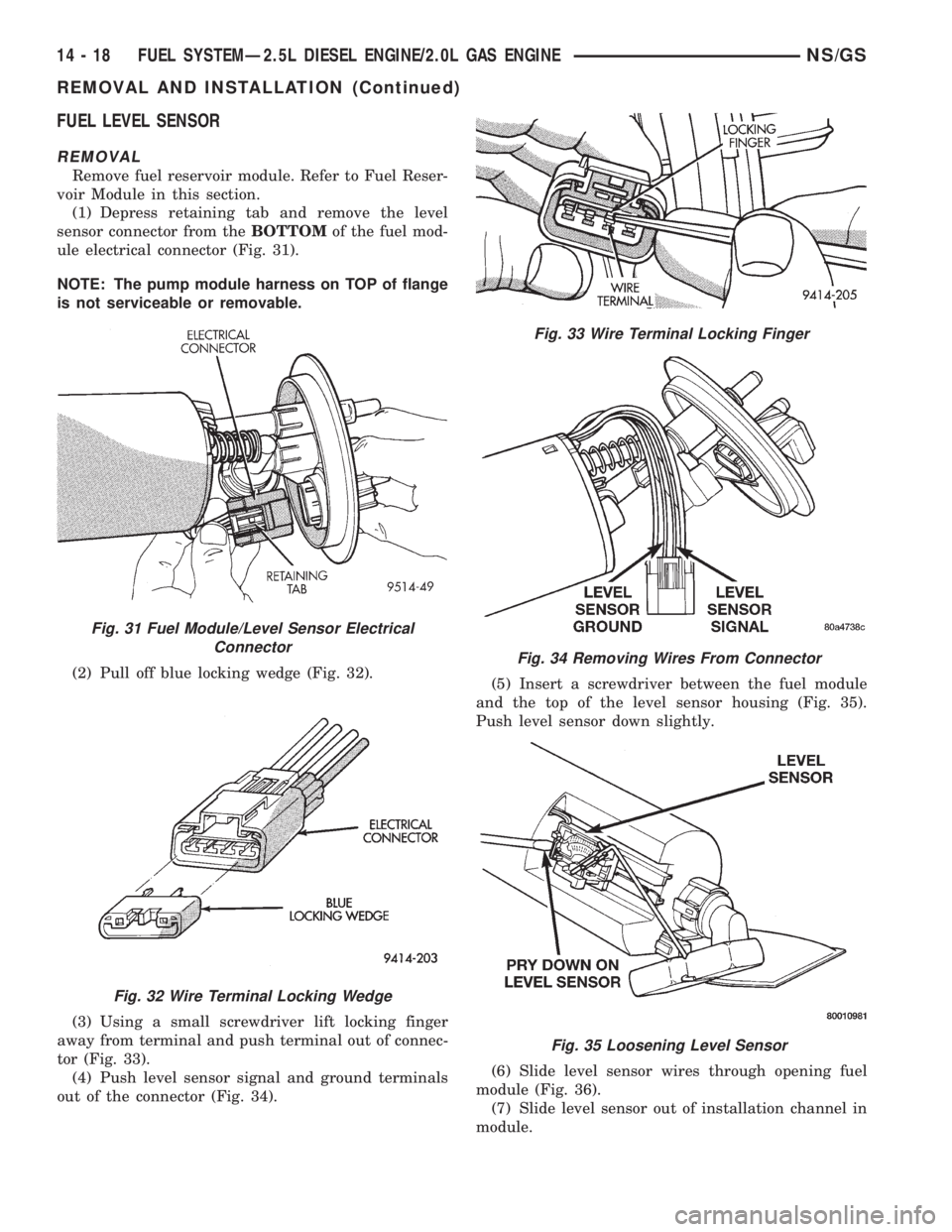
(1) Depress retaining tab and remove the level
sensor connector from theBOTTOMof the fuel mod-
ule electrical connector (Fig. 31).
NOTE: The pump module harness on TOP of flange
is not serviceable or removable.
(2) Pull off blue locking wedge (Fig. 32).
(3) Using a small screwdriver lift locking finger
away from terminal and push terminal out of connec-
tor (Fig. 33).
(4) Push level sensor signal and ground terminals
out of the connector (Fig. 34).(5) Insert a screwdriver between the fuel module
and the top of the level sensor housing (Fig. 35).
Push level sensor down slightly.
(6) Slide level sensor wires through opening fuel
module (Fig. 36).
(7) Slide level sensor out of installation channel in
module.
Fig. 31 Fuel Module/Level Sensor Electrical
Connector
Fig. 32 Wire Terminal Locking Wedge
Fig. 33 Wire Terminal Locking Finger
Fig. 34 Removing Wires From Connector
Fig. 35 Loosening Level Sensor
14 - 18 FUEL SYSTEMÐ2.5L DIESEL ENGINE/2.0L GAS ENGINENS/GS
REMOVAL AND INSTALLATION (Continued)