1996 CHRYSLER VOYAGER fuel filter location
[x] Cancel search: fuel filter locationPage 1055 of 1938
CAUTION: Be sure that the tapped holes maintain
the original centerline.
Heli-Coil tools and inserts are readily available
from automotive parts jobbers.
HYDROSTATIC LOCKED ENGINE
When an engine is suspected to be hydrostatically
locked, regardless of what caused the problem, these
steps should be used.
CAUTION: Do Not Use Starter Motor To Rotate
Engine, severe damage may occur.
(1) Inspect air cleaner, induction system and
intake manifold to insure system is dry and clear of
foreign material.
(2) Remove negative battery cable.
(3) Place a shop towel around the spark plugs
when removing them from the engine. This will catch
any fluid that may possibly be in the cylinder under
pressure.
(4) With all spark plugs removed, rotate engine
crankshaft using a breaker bar and socket.
(5) Identify the fluid in the cylinder(s) (i.e., cool-
ant, fuel, oil or other).
(6) Make sure all fluid has been removed from the
cylinders. Inspect engine for damage (i.e., Connecting
Rods, Pistons, Valves etc.)
(7) Repair engine or components as necessary to
prevent this problem from occurring again.
CAUTION: Squirt approximately 1 teaspoon of oil
into cylinders, rotate engine to lubricate the cylin-
der walls to prevent damage on restart.
(8) Install new spark plugs.
(9) Drain engine oil and remove oil filter.
(10) Fill engine with specified amount of approved
oil and install new oil filter.
(11) Connect negative battery cable.
(12) Start engine and check for any leaks.
ENGINE OIL
Checking Oil Level
To assure proper engine lubrication, the engine oil
must be maintained at the correct level. Check the
oil level at regular intervals, such as every fuel stop.
The best time to check the oil level is about 5 min-
utes after a fully warmed-up engine is shut off, or
before starting the vehicle after it has sat overnight.
Checking the oil while the vehicle is on level
ground, will improve the accuracy of the oil level
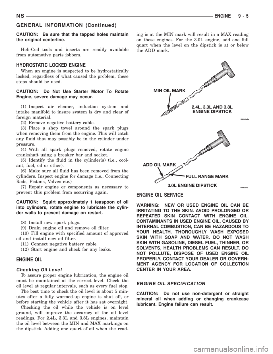
readings. For 2.4L, 3.3L and 3.8L engines, maintain
the oil level between the MIN and MAX markings on
the dipstick. Adding one quart of oil when the read-ing is at the MIN mark will result in a MAX reading
on these engines. For the 3.0L engine, add one full
quart when the level on the dipstick is at or below
the ADD mark.
ENGINE OIL SERVICE
WARNING: NEW OR USED ENGINE OIL CAN BE
IRRITATING TO THE SKIN. AVOID PROLONGED OR
REPEATED SKIN CONTACT WITH ENGINE OIL.
CONTAMINANTS IN USED ENGINE OIL, CAUSED BY
INTERNAL COMBUSTION, CAN BE HAZARDOUS TO
YOUR HEALTH. THOROUGHLY WASH EXPOSED
SKIN WITH SOAP AND WATER. DO NOT WASH
SKIN WITH GASOLINE, DIESEL FUEL, THINNER, OR
SOLVENTS, HEALTH PROBLEMS CAN RESULT. DO
NOT POLLUTE, DISPOSE OF USED ENGINE OIL
PROPERLY. CONTACT YOUR DEALER OR GOVERN-
MENT AGENCY FOR LOCATION OF COLLECTION
CENTER IN YOUR AREA.
ENGINE OIL SPECIFICATION
CAUTION: Do not use non-detergent or straight
mineral oil when adding or changing crankcase
lubricant. Engine failure can result.
NSENGINE 9 - 5
GENERAL INFORMATION (Continued)
Page 1226 of 1938
ENGINE OIL CHANGE
WARNING: NEW OR USED ENGINE OIL CAN BE
IRRITATING TO THE SKIN. AVOID PROLONGED OR
REPEATED SKIN CONTACT WITH ENGINE OIL.
CONTAMINANTS IN USED ENGINE OIL, CAUSED BY
INTERNAL COMBUSTION, CAN BE HAZARDOUS TO
YOUR HEALTH. THOROUGHLY WASH EXPOSED
SKIN WITH SOAP AND WATER. DO NOT WASH
SKIN WITH GASOLINE, DIESEL FUEL, THINNER, OR
SOLVENTS, HEALTH PROBLEMS CAN RESULT. DO
NOT POLLUTE, DISPOSE OF USED ENGINE OIL
PROPERLY. CONTACT YOUR DEALER OR GOVERN-
MENT AGENCY FOR LOCATION OF COLLECTION
CENTER IN YOUR AREA.
Run engine until achieving normal operating tem-
perature.
(1) Position the vehicle on a level surface and turn
engine off.
(2) Remove oil fill cap.
(3) Hoist vehicle. Refer to Hoisting and Jacking
Recommendations.
(4) Place a suitable drain pan under crankcase
drain.
(5) Remove drain plug from crankcase and allow
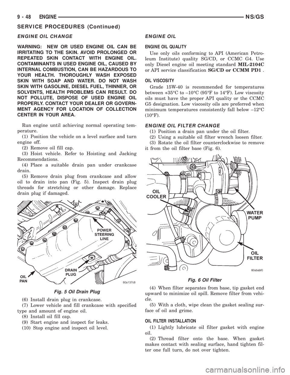
oil to drain into pan (Fig. 5). Inspect drain plug
threads for stretching or other damage. Replace
drain plug if damaged.
(6) Install drain plug in crankcase.
(7) Lower vehicle and fill crankcase with specified
type and amount of engine oil.
(8) Install oil fill cap.
(9) Start engine and inspect for leaks.
(10) Stop engine and inspect oil level.
ENGINE OIL
ENGINE OIL QUALITY
Use only oils conforming to API (American Petro-
leum Institute) quality SG/CD, or CCMC G4. Use
only Diesel engine oil meeting standardMIL-2104C
or API service classificationSG/CD or CCMM PD1.
OIL VISCOSITY
Grade 15W-40 is recommended for temperatures
between +35ÉC to ±10ÉC (95ÉF to 14ÉF). Low viscosity
oils must have the proper API quality or the CCMC
G5 designation. Low viscosity oils are preferred when
minimum temperatures consistently fall below ±12ÉC
(10ÉF).
ENGINE OIL FILTER CHANGE
(1) Position a drain pan under the oil filter.
(2) Using a suitable oil filter wrench loosen filter.
(3) Rotate the oil filter counterclockwise to remove
it from the oil filter base (Fig. 6).
(4) When filter separates from base, tip gasket end
upward to minimize oil spill. Remove filter from vehi-
cle.
(5) With a cloth, wipe clean the gasket sealing sur-
face of oil and grime.
OIL FILTER INSTALLATION
(1) Lightly lubricate oil filter gasket with engine
oil.
(2) Thread filter onto the base. When gasket
makes contact with sealing surface, hand tighten fil-
ter one full turn, do not over tighten.
Fig. 5 Oil Drain Plug
Fig. 6 Oil Filter
9 - 48 ENGINENS/GS
SERVICE PROCEDURES (Continued)
Page 1330 of 1938
The crankshaft position sensor is located in the
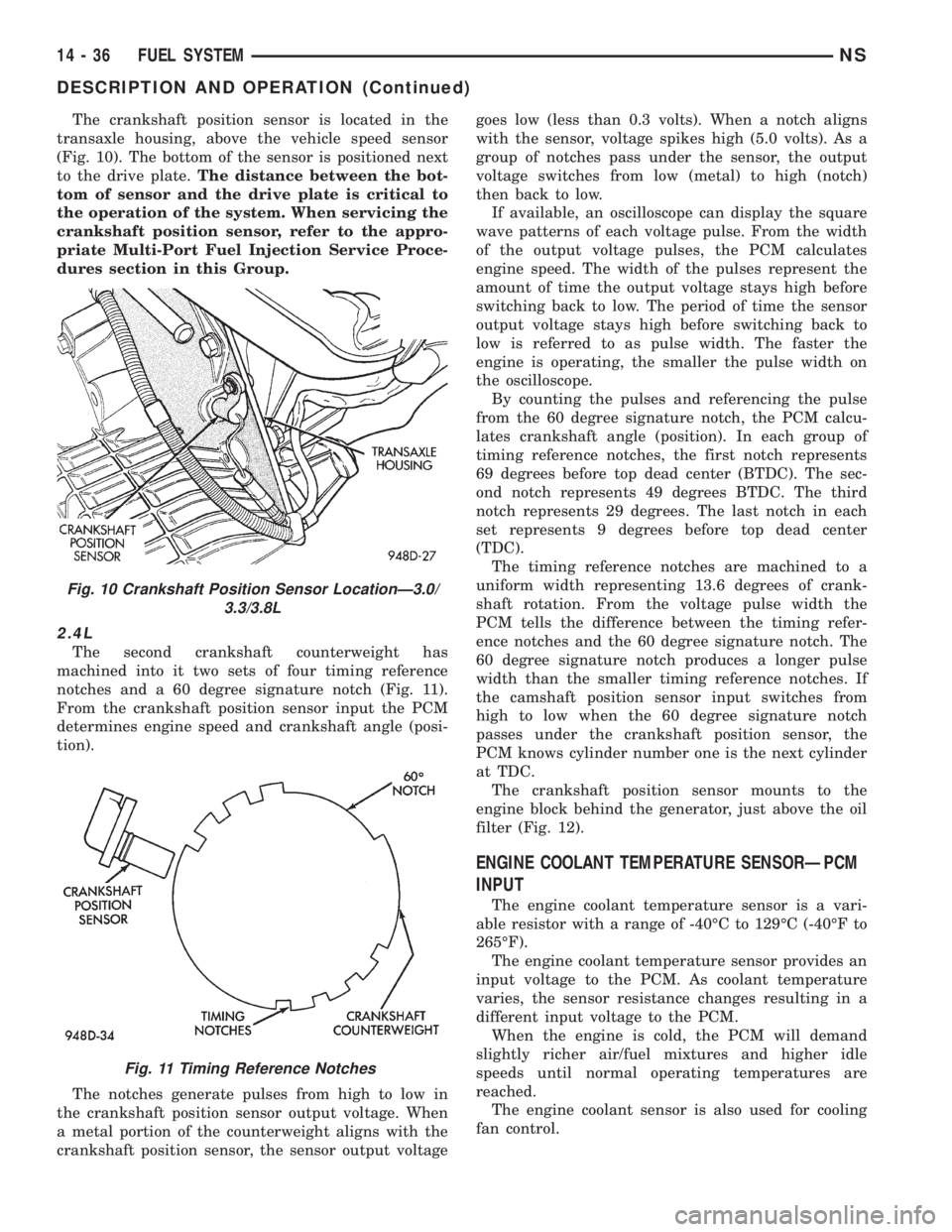
transaxle housing, above the vehicle speed sensor
(Fig. 10). The bottom of the sensor is positioned next
to the drive plate.The distance between the bot-
tom of sensor and the drive plate is critical to
the operation of the system. When servicing the
crankshaft position sensor, refer to the appro-
priate Multi-Port Fuel Injection Service Proce-
dures section in this Group.
2.4L
The second crankshaft counterweight has
machined into it two sets of four timing reference
notches and a 60 degree signature notch (Fig. 11).
From the crankshaft position sensor input the PCM
determines engine speed and crankshaft angle (posi-
tion).
The notches generate pulses from high to low in
the crankshaft position sensor output voltage. When
a metal portion of the counterweight aligns with the
crankshaft position sensor, the sensor output voltagegoes low (less than 0.3 volts). When a notch aligns
with the sensor, voltage spikes high (5.0 volts). As a
group of notches pass under the sensor, the output
voltage switches from low (metal) to high (notch)
then back to low.
If available, an oscilloscope can display the square
wave patterns of each voltage pulse. From the width
of the output voltage pulses, the PCM calculates
engine speed. The width of the pulses represent the
amount of time the output voltage stays high before
switching back to low. The period of time the sensor
output voltage stays high before switching back to
low is referred to as pulse width. The faster the
engine is operating, the smaller the pulse width on
the oscilloscope.
By counting the pulses and referencing the pulse
from the 60 degree signature notch, the PCM calcu-
lates crankshaft angle (position). In each group of
timing reference notches, the first notch represents
69 degrees before top dead center (BTDC). The sec-
ond notch represents 49 degrees BTDC. The third
notch represents 29 degrees. The last notch in each
set represents 9 degrees before top dead center
(TDC).
The timing reference notches are machined to a
uniform width representing 13.6 degrees of crank-
shaft rotation. From the voltage pulse width the
PCM tells the difference between the timing refer-
ence notches and the 60 degree signature notch. The
60 degree signature notch produces a longer pulse
width than the smaller timing reference notches. If
the camshaft position sensor input switches from
high to low when the 60 degree signature notch
passes under the crankshaft position sensor, the
PCM knows cylinder number one is the next cylinder
at TDC.
The crankshaft position sensor mounts to the
engine block behind the generator, just above the oil
filter (Fig. 12).
ENGINE COOLANT TEMPERATURE SENSORÐPCM
INPUT
The engine coolant temperature sensor is a vari-
able resistor with a range of -40ÉC to 129ÉC (-40ÉF to
265ÉF).
The engine coolant temperature sensor provides an
input voltage to the PCM. As coolant temperature
varies, the sensor resistance changes resulting in a
different input voltage to the PCM.
When the engine is cold, the PCM will demand
slightly richer air/fuel mixtures and higher idle
speeds until normal operating temperatures are
reached.
The engine coolant sensor is also used for cooling
fan control.
Fig. 10 Crankshaft Position Sensor LocationÐ3.0/
3.3/3.8L
Fig. 11 Timing Reference Notches
14 - 36 FUEL SYSTEMNS
DESCRIPTION AND OPERATION (Continued)
Page 1369 of 1938
FUEL SYSTEMÐ2.5L DIESEL ENGINE/2.0L GAS ENGINE
CONTENTS
page page
FUEL DELIVERY SYSTEMÐ2.0L ENGINE.... 28
FUEL DELIVERY SYSTEMÐ2.5L DIESEL
ENGINE.............................. 3
FUEL INJECTION SYSTEMÐ2.0L ENGINE . . . 32FUEL INJECTION SYSTEMÐ2.5L DIESEL
ENGINE............................. 43
GENERAL INFORMATION.................. 1
GENERAL INFORMATION
INDEX
page page
GENERAL INFORMATION
FUEL REQUIREMENTSÐ2.0L ENGINE....... 2
FUEL REQUIREMENTSÐ2.5L DIESEL........ 2GASOLINE/OXYGENATE BLENDS........... 2
INTRODUCTIONÐ2.0L ENGINE............. 2
INTRODUCTIONÐ2.5L DIESEL............. 1
GENERAL INFORMATION
INTRODUCTIONÐ2.5L DIESEL
Certain components of the fuel system on the 2.5L
diesel engine are controlled by the Bosch Engine con-
troller which is a Powertrain Control Module (PCM).
Refer to Powertrain Control Module in the Fuel
Injection SystemÐ2.5L Diesel Engine section of this
group for a list of items controlled by the PCM. The
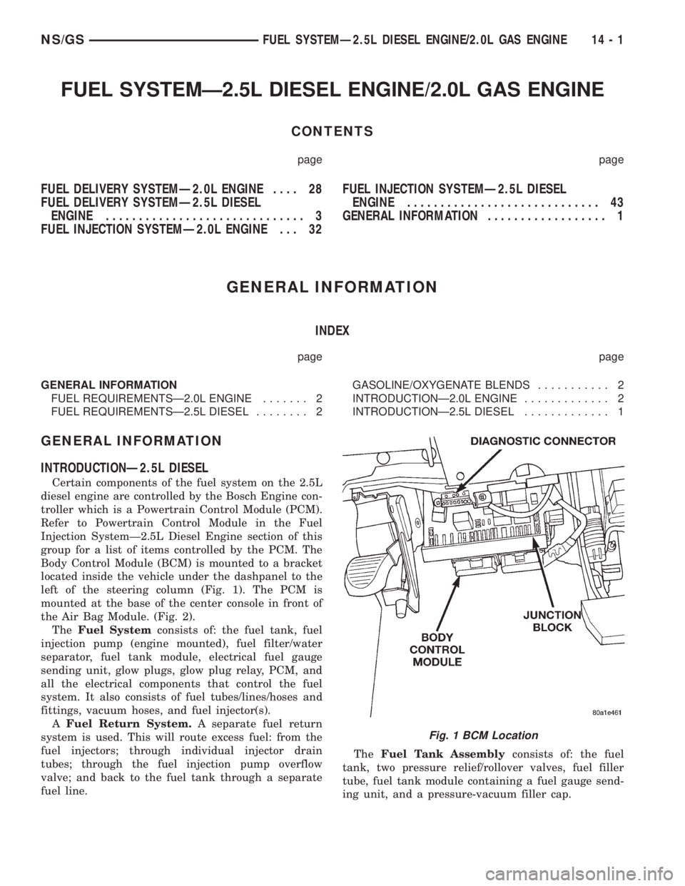
Body Control Module (BCM) is mounted to a bracket
located inside the vehicle under the dashpanel to the
left of the steering column (Fig. 1). The PCM is
mounted at the base of the center console in front of
the Air Bag Module. (Fig. 2).
TheFuel Systemconsists of: the fuel tank, fuel
injection pump (engine mounted), fuel filter/water
separator, fuel tank module, electrical fuel gauge
sending unit, glow plugs, glow plug relay, PCM, and
all the electrical components that control the fuel
system. It also consists of fuel tubes/lines/hoses and
fittings, vacuum hoses, and fuel injector(s).
AFuel Return System.A separate fuel return
system is used. This will route excess fuel: from the
fuel injectors; through individual injector drain
tubes; through the fuel injection pump overflow
valve; and back to the fuel tank through a separate
fuel line.TheFuel Tank Assemblyconsists of: the fuel
tank, two pressure relief/rollover valves, fuel filler
tube, fuel tank module containing a fuel gauge send-
ing unit, and a pressure-vacuum filler cap.
Fig. 1 BCM Location
NS/GSFUEL SYSTEMÐ2.5L DIESEL ENGINE/2.0L GAS ENGINE 14 - 1
Page 1372 of 1938
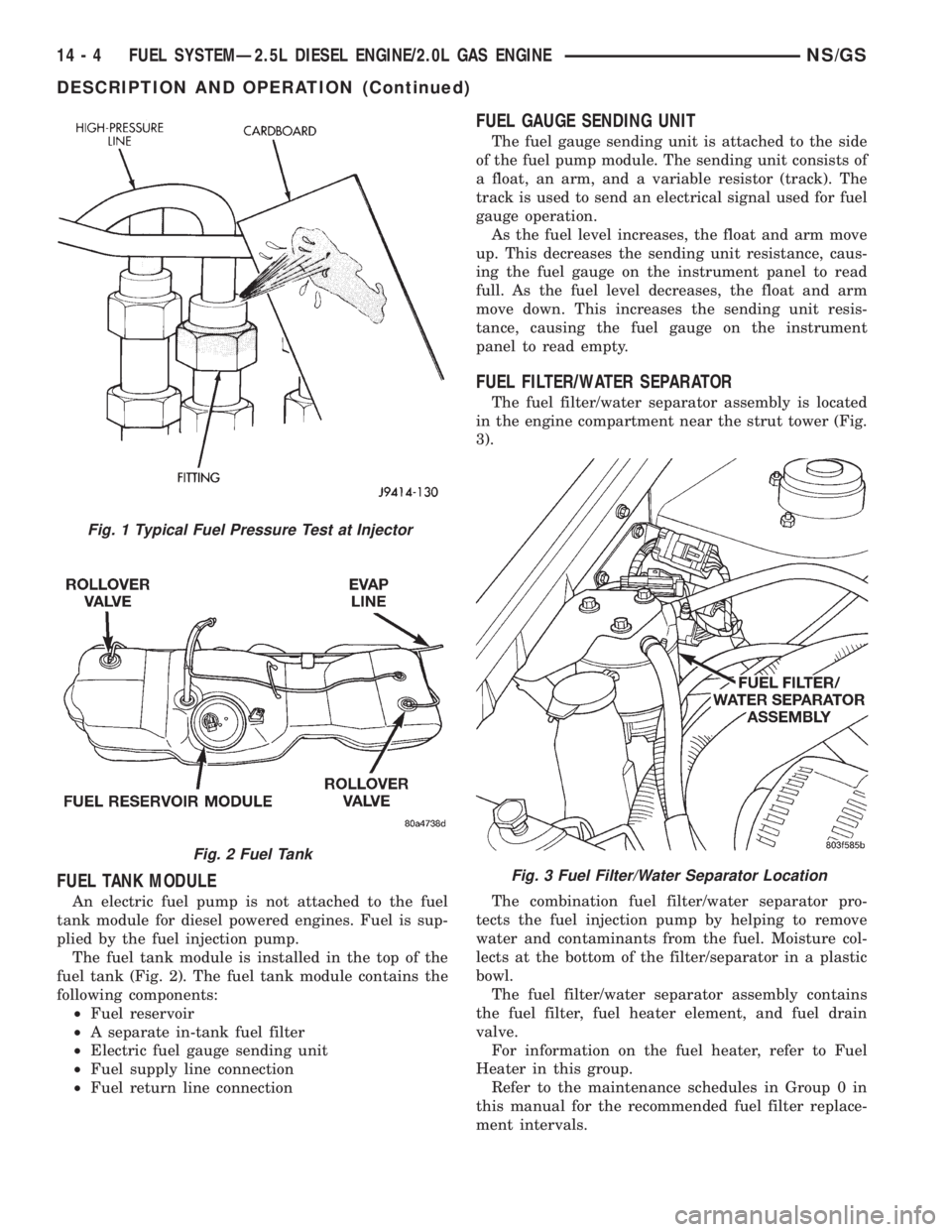
FUEL TANK MODULE
An electric fuel pump is not attached to the fuel
tank module for diesel powered engines. Fuel is sup-
plied by the fuel injection pump.
The fuel tank module is installed in the top of the
fuel tank (Fig. 2). The fuel tank module contains the
following components:
²Fuel reservoir
²A separate in-tank fuel filter
²Electric fuel gauge sending unit
²Fuel supply line connection
²Fuel return line connection
FUEL GAUGE SENDING UNIT
The fuel gauge sending unit is attached to the side
of the fuel pump module. The sending unit consists of
a float, an arm, and a variable resistor (track). The
track is used to send an electrical signal used for fuel
gauge operation.
As the fuel level increases, the float and arm move
up. This decreases the sending unit resistance, caus-
ing the fuel gauge on the instrument panel to read
full. As the fuel level decreases, the float and arm
move down. This increases the sending unit resis-
tance, causing the fuel gauge on the instrument
panel to read empty.
FUEL FILTER/WATER SEPARATOR
The fuel filter/water separator assembly is located
in the engine compartment near the strut tower (Fig.
3).
The combination fuel filter/water separator pro-
tects the fuel injection pump by helping to remove
water and contaminants from the fuel. Moisture col-
lects at the bottom of the filter/separator in a plastic
bowl.
The fuel filter/water separator assembly contains
the fuel filter, fuel heater element, and fuel drain
valve.
For information on the fuel heater, refer to Fuel
Heater in this group.
Refer to the maintenance schedules in Group 0 in
this manual for the recommended fuel filter replace-
ment intervals.
Fig. 1 Typical Fuel Pressure Test at Injector
Fig. 2 Fuel Tank
Fig. 3 Fuel Filter/Water Separator Location
14 - 4 FUEL SYSTEMÐ2.5L DIESEL ENGINE/2.0L GAS ENGINENS/GS
DESCRIPTION AND OPERATION (Continued)
Page 1373 of 1938
For periodic draining of water from the bowl, refer
to Fuel Filter/Water Separator Removal/Installation
in this group.
FUEL SHUTDOWN SOLENOID
The fuel shutdown solenoid is controlled and
operated by the PCM.
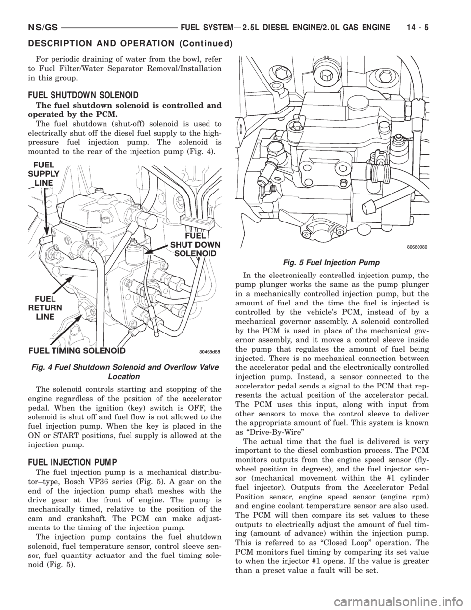
The fuel shutdown (shut-off) solenoid is used to
electrically shut off the diesel fuel supply to the high-
pressure fuel injection pump. The solenoid is
mounted to the rear of the injection pump (Fig. 4).
The solenoid controls starting and stopping of the
engine regardless of the position of the accelerator
pedal. When the ignition (key) switch is OFF, the
solenoid is shut off and fuel flow is not allowed to the
fuel injection pump. When the key is placed in the
ON or START positions, fuel supply is allowed at the
injection pump.
FUEL INJECTION PUMP
The fuel injection pump is a mechanical distribu-
tor±type, Bosch VP36 series (Fig. 5). A gear on the
end of the injection pump shaft meshes with the
drive gear at the front of engine. The pump is
mechanically timed, relative to the position of the
cam and crankshaft. The PCM can make adjust-
ments to the timing of the injection pump.
The injection pump contains the fuel shutdown
solenoid, fuel temperature sensor, control sleeve sen-
sor, fuel quantity actuator and the fuel timing sole-
noid (Fig. 5).In the electronically controlled injection pump, the
pump plunger works the same as the pump plunger
in a mechanically controlled injection pump, but the
amount of fuel and the time the fuel is injected is
controlled by the vehicle's PCM, instead of by a
mechanical governor assembly. A solenoid controlled
by the PCM is used in place of the mechanical gov-
ernor assembly, and it moves a control sleeve inside
the pump that regulates the amount of fuel being
injected. There is no mechanical connection between
the accelerator pedal and the electronically controlled
injection pump. Instead, a sensor connected to the
accelerator pedal sends a signal to the PCM that rep-
resents the actual position of the accelerator pedal.
The PCM uses this input, along with input from
other sensors to move the control sleeve to deliver
the appropriate amount of fuel. This system is known
as ªDrive-By-Wireº
The actual time that the fuel is delivered is very
important to the diesel combustion process. The PCM
monitors outputs from the engine speed sensor (fly-
wheel position in degrees), and the fuel injector sen-
sor (mechanical movement within the #1 cylinder
fuel injector). Outputs from the Accelerator Pedal
Position sensor, engine speed sensor (engine rpm)
and engine coolant temperature sensor are also used.
The PCM will then compare its set values to these
outputs to electrically adjust the amount of fuel tim-
ing (amount of advance) within the injection pump.
This is referred to as ªClosed Loopº operation. The
PCM monitors fuel timing by comparing its set value
to when the injector #1 opens. If the value is greater
than a preset value a fault will be set.
Fig. 4 Fuel Shutdown Solenoid and Overflow Valve
Location
Fig. 5 Fuel Injection Pump
NS/GSFUEL SYSTEMÐ2.5L DIESEL ENGINE/2.0L GAS ENGINE 14 - 5
DESCRIPTION AND OPERATION (Continued)
Page 1376 of 1938
FUEL HEATER
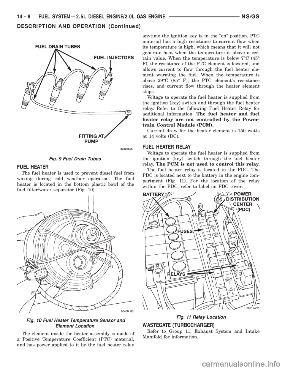
The fuel heater is used to prevent diesel fuel from
waxing during cold weather operation. The fuel
heater is located in the bottom plastic bowl of the
fuel filter/water separator (Fig. 10).
The element inside the heater assembly is made of
a Positive Temperature Coefficient (PTC) material,
and has power applied to it by the fuel heater relayanytime the ignition key is in the ªonº position. PTC
material has a high resistance to current flow when
its temperature is high, which means that it will not
generate heat when the temperature is above a cer-
tain value. When the temperature is below 7ÉC (45É
F), the resistance of the PTC element is lowered, and
allows current to flow through the fuel heater ele-
ment warming the fuel. When the temperature is
above 29ÉC (85É F), the PTC element's resistance
rises, and current flow through the heater element
stops.
Voltage to operate the fuel heater is supplied from
the ignition (key) switch and through the fuel heater
relay. Refer to the following Fuel Heater Relay for
additional information.The fuel heater and fuel
heater relay are not controlled by the Power-
train Control Module (PCM).
Current draw for the heater element is 150 watts
at 14 volts (DC).
FUEL HEATER RELAY
Voltage to operate the fuel heater is supplied from
the ignition (key) switch through the fuel heater
relay.The PCM is not used to control this relay.
The fuel heater relay is located in the PDC. The
PDC is located next to the battery in the engine com-
partment (Fig. 11). For the location of the relay
within the PDC, refer to label on PDC cover.
WASTEGATE (TURBOCHARGER)
Refer to Group 11, Exhaust System and Intake
Manifold for information.
Fig. 9 Fuel Drain Tubes
Fig. 10 Fuel Heater Temperature Sensor and
Element LocationFig. 11 Relay Location
14 - 8 FUEL SYSTEMÐ2.5L DIESEL ENGINE/2.0L GAS ENGINENS/GS
DESCRIPTION AND OPERATION (Continued)
Page 1378 of 1938
(7) Inspect the starter motor and starter solenoid
connections for tightness and corrosion.
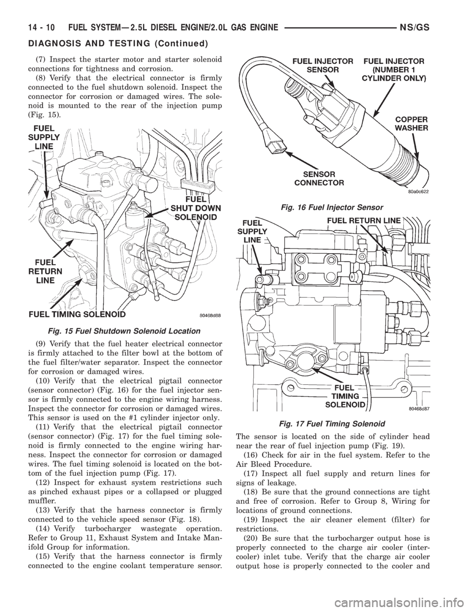
(8) Verify that the electrical connector is firmly
connected to the fuel shutdown solenoid. Inspect the
connector for corrosion or damaged wires. The sole-
noid is mounted to the rear of the injection pump
(Fig. 15).
(9) Verify that the fuel heater electrical connector
is firmly attached to the filter bowl at the bottom of
the fuel filter/water separator. Inspect the connector
for corrosion or damaged wires.
(10) Verify that the electrical pigtail connector
(sensor connector) (Fig. 16) for the fuel injector sen-
sor is firmly connected to the engine wiring harness.
Inspect the connector for corrosion or damaged wires.
This sensor is used on the #1 cylinder injector only.
(11) Verify that the electrical pigtail connector
(sensor connector) (Fig. 17) for the fuel timing sole-
noid is firmly connected to the engine wiring har-
ness. Inspect the connector for corrosion or damaged
wires. The fuel timing solenoid is located on the bot-
tom of the fuel injection pump (Fig. 17).
(12) Inspect for exhaust system restrictions such
as pinched exhaust pipes or a collapsed or plugged
muffler.
(13) Verify that the harness connector is firmly
connected to the vehicle speed sensor (Fig. 18).
(14) Verify turbocharger wastegate operation.
Refer to Group 11, Exhaust System and Intake Man-
ifold Group for information.
(15) Verify that the harness connector is firmly
connected to the engine coolant temperature sensor.The sensor is located on the side of cylinder head
near the rear of fuel injection pump (Fig. 19).
(16) Check for air in the fuel system. Refer to the
Air Bleed Procedure.
(17) Inspect all fuel supply and return lines for
signs of leakage.
(18) Be sure that the ground connections are tight
and free of corrosion. Refer to Group 8, Wiring for
locations of ground connections.
(19) Inspect the air cleaner element (filter) for
restrictions.
(20) Be sure that the turbocharger output hose is
properly connected to the charge air cooler (inter-
cooler) inlet tube. Verify that the charge air cooler
output hose is properly connected to the cooler and
Fig. 15 Fuel Shutdown Solenoid Location
Fig. 16 Fuel Injector Sensor
Fig. 17 Fuel Timing Solenoid
14 - 10 FUEL SYSTEMÐ2.5L DIESEL ENGINE/2.0L GAS ENGINENS/GS
DIAGNOSIS AND TESTING (Continued)