Page 10 of 40
19-8
21 -
Lower coolant line
Coolant hose connection diagram page 19
-9
22 -
Oil cooler
23 -
Belt pulley
For viscous fan
24 -
Fan wheel for viscous fan
25 -
Viscous fan coupling Note left-hand threadTightening torque only valid when using
3312 open end spanner. Tighten to 40 Nm (30 ft lb)Removing and installing page 19
-25
26 -
Bracket
For viscous fan
27 -
From bottom of radiator Coolant hose connection diagram page 19
-9
Pa
ge 10 of 40 Coolin
g system com
ponents, removin
g and installin
g
11/21/2002 htt
p://127.0.0.1:8080/audi/servlet/Dis
play?action=Goto&t
yp
e=re
pair&id=AUDI.B5.GE03.19.1
Page 11 of 40
19-9
Coolant hose connection diagram
1 -
Lower coolant hose
From radiator to engine
2 -
Cylinder head/cylinder block
3 -
Intake manifold
4 -
Coolant line From heat exchanger to engine block
5 -
Heater core
6 -
Coolant hose To heat exchanger
7 -
Rear coolant line
8 -
Expansion tank
Pa
ge 11 of 40 Coolin
g system com
ponents, removin
g and installin
g
11/21/2002 htt
p://127.0.0.1:8080/audi/servlet/Dis
play?action=Goto&t
yp
e=re
pair&id=AUDI.B5.GE03.19.1
Page 12 of 40
19-10
9 -
Oil cooler
10 -
Coolant line
From expansion tank to lower coolant pipe
11 -
Upper coolant hose
12 -
Radiator
13 -
Coolant pump
14 -
Lower coolant line
15 -
Connection For thermostat
Pa
ge 12 of 40 Coolin
g system com
ponents, removin
g and installin
g
11/21/2002 htt
p://127.0.0.1:8080/audi/servlet/Dis
play?action=Goto&t
yp
e=re
pair&id=AUDI.B5.GE03.19.1
Page 13 of 40
19-11
Cooling system, draining and refilling
Draining
WARNING!
The cooling system is pressurized when the
engine is warm. When opening the expansion
tank, wear gloves and other appropriate
protection, cover the cap with a cloth and
open carefully to relieve system pressure
slowly.
- Open coolant expansion tank cap.
- Remove noise insulation panel.
- Place VAG1306 drip tray underneath engine.
- With bumper removed, open coolant drain plug (arrow) on lower left of
radiator by turning it counterclockwise. If necessary, attach accessory
hose to connection.
-
With bumper installed, pull off retaining clamp for lower right radiator
Pa
ge 13 of 40 Coolin
g system com
ponents, removin
g and installin
g
11/21/2002 htt
p://127.0.0.1:8080/audi/servlet/Dis
play?action=Goto&t
yp
e=re
pair&id=AUDI.B5.GE03.19.1
Page 14 of 40
CAUTION!
Follow disposal regulations for coolant. hose (from radiator to engine) and disconnect radiator hose from
radiator.
Pa
ge 14 of 40 Coolin
g system com
ponents, removin
g and installin
g
11/21/2002 htt
p://127.0.0.1:8080/audi/servlet/Dis
play?action=Goto&t
yp
e=re
pair&id=AUDI.B5.GE03.19.1
Page 15 of 40

19-12
Filling
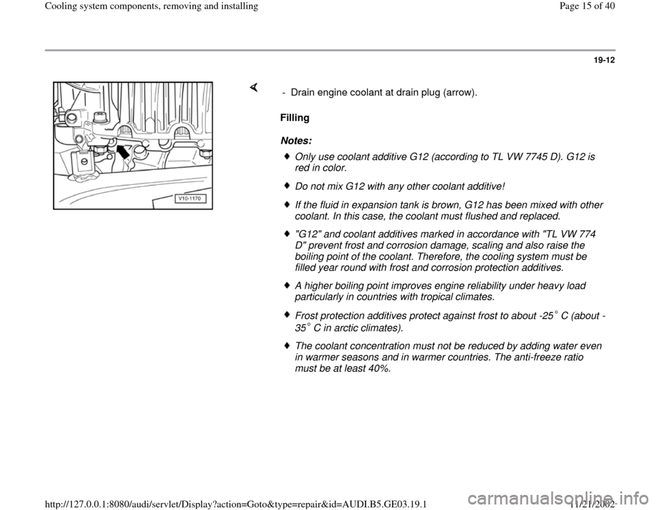
Notes: - Drain engine coolant at drain plug (arrow).
Only use coolant additive G12 (according to TL VW 7745 D). G12 is
red in color. Do not mix G12 with any other coolant additive!If the fluid in expansion tank is brown, G12 has been mixed with other
coolant. In this case, the coolant must flushed and replaced. "G12" and coolant additives marked in accordance with "TL VW 774
D" prevent frost and corrosion damage, scaling and also raise the
boiling point of the coolant. Therefore, the cooling system must be
filled year round with frost and corrosion protection additives. A higher boiling point improves engine reliability under heavy load
particularly in countries with tropical climates. Frost protection additives protect against frost to about -25 C (about -
35 C in arctic climates). The coolant concentration must not be reduced by adding water even
in warmer seasons and in warmer countries. The anti-freeze ratio
must be at least 40%.
Pa
ge 15 of 40 Coolin
g system com
ponents, removin
g and installin
g
11/21/2002 htt
p://127.0.0.1:8080/audi/servlet/Dis
play?action=Goto&t
yp
e=re
pair&id=AUDI.B5.GE03.19.1
Page 16 of 40
19-13
Note (continued from page Page 19
-12
):
If for climatic reasons greater frost protection is
required, the amount of G 12 can be increased,
but only up to 60% (frost protection to about -
40 C), otherwise frost protection and cooling
effectiveness will be reduced.
If the radiator, heat exchanger, cylinder head or
cylinder head gasket is replaced, completely
replace the engine coolant.
Test coolant frost protection using T10007 special tool.
Recommended mixture ratios: 1) The quantity of coolant can vary depending upon the equipment
installed in the vehicle. Frost protection
to Anti-freeze
amount G 121)
Water 1)
-25 C (-13 F)
-35 C (-31 F)
40 %
50 % 2.5 l (2.7
qt.)
3.0 l (3.2
qt.) 3.5 l (3.7
qt.)
3.0 l (3.2
qt.)
Pa
ge 16 of 40 Coolin
g system com
ponents, removin
g and installin
g
11/21/2002 htt
p://127.0.0.1:8080/audi/servlet/Dis
play?action=Goto&t
yp
e=re
pair&id=AUDI.B5.GE03.19.1
Page 17 of 40
19-14
- Replace coolant drain plug O-ring and install
coolant drain plug into engine.
Tightening torque: 20 Nm (15 ft lb).
- Install lower right coolant hose and secure with
retaining clip.
- Secure coolant drain valve to radiator.
- Screw VAG1274/9 onto expansion tank and insert VAG1274/10 into
adapter.
- Loosen clamp on coolant hose on heater core and pull back hose until
bleeder hole in coolant hose (arrow) is no longer sealed by connection.
- Top off coolant until it flows out from bleeder hole in coolant hose.
- Push coolant hose onto connection and tighten.
Pa
ge 17 of 40 Coolin
g system com
ponents, removin
g and installin
g
11/21/2002 htt
p://127.0.0.1:8080/audi/servlet/Dis
play?action=Goto&t
yp
e=re
pair&id=AUDI.B5.GE03.19.1