Page 17 of 47
01-127
VAG1598/12 adapter cable Measuring range: Resistance measurement (200 ohm)
Test
step VAG1598
socket Test of
Test
conditions
- additional
steps Specified
values Corrective action
4.3 2 + 10 Temperature Regulator
Flap Motor -V68- 20 W to 100
W - Determine and rectify open circuit in
wiring, contact resistance or short circuit
using wiring diagram.
- Replace applicable flap motor page
87
-106
.
4.4 4 + 12 Central Flap Motor -V70- 20 W to 100
W
4.5 5 + 13 Air Flow Flap Motor -V71- 20 W to 100
W
4.6 3 + 11 Footwell/Defroster Flap
Motor -V85- 20 W to 100
W
Pa
ge 17 of 47 A/C s
ystem, electrical testin
g
11/21/2002 htt
p://127.0.0.1:8080/audi/servlet/Dis
play?action=Goto&t
yp
e=re
pair&id=AUDI.B5.HA01.01.2
Page 18 of 47

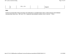
Note:
Electrical test steps 5.1 to 5.4 do not apply t")
01-128
Test No. 5 (A/C Compressor Speed Sensor -G111-, refrigerant pressure switches -F118-, -F73- and Interior
Temperature Sensor Fan -V42-)
Note:
Electrical test steps 5.1 to 5.4 do not apply to vehicles equipped with Nippondenso compressors (A/C compressor speed
sensor G111 is not installed on Nippondenso compressors). VAG1598/11 adapter cable Measuring range: Resistance measurement (20 kilo ohm)
Test
step VAG1598
socket Test of
Test
conditions
- additional
steps Specified
values Corrective action
5.1 5 + 49 A/C Compressor
Speed Sender -G111-
- 0.8 kW to
1.5 kW - Determine and rectify open circuit in
wiring, contact resistance or short circuit
using wiring diagram.
- Replace -G111- page 87
-63
.
5.2 5 and
ground A/C Compressor
Speed Sender -G111-
- greater
than
2 kW - Determine and rectify short circuit using
wiring diagram.
- Replace -G111- page 87
-63
.
Pa
ge 18 of 47 A/C s
ystem, electrical testin
g
11/21/2002 htt
p://127.0.0.1:8080/audi/servlet/Dis
play?action=Goto&t
yp
e=re
pair&id=AUDI.B5.HA01.01.2
Page 19 of 47

Test
step VAG1598
socket Test of
Test conditions
- additional steps Specified
values Corrective action
5.3")
01-129
VAG1598/11 adapter cable Measuring range: Voltage measurement (20 V)
Test
step VAG1598
socket Test of
Test conditions
- additional steps Specified
values Corrective action
5.3 5 and
ground A/C Compressor Speed
Sender -G111-
Engine running Compressor not
running - less than 1
V - Determine and rectify short
circuit using wiring diagram.
VAG1598/11 adapter cable Measuring range: Voltage measurement (2 V)
Note: additional test steps before proceeding with this test. Test
step VAG1598
socket Test of
Test conditions
- additional steps Specified values
Corrective
action
5.4 5 and
ground A/C Compressor
Speed Sender -
G111-
Engine running Compressor running
- Relay for A/C Clutch removed
- Bridge terminals 30 + 87 at relay
connector base (A/C Clutch
switched on) - greater than 0.05 V
(depends on engine
speed) - Replace -G111-
page 87
-63
.
Pa
ge 19 of 47 A/C s
ystem, electrical testin
g
11/21/2002 htt
p://127.0.0.1:8080/audi/servlet/Dis
play?action=Goto&t
yp
e=re
pair&id=AUDI.B5.HA01.01.2
Page 20 of 47
01-130
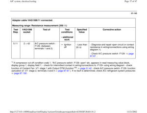
VAG1598/11 adapter cable Measuring range: Resistance measurement (200 ohm)
Test
step VAG1598
socket Test of
Test
conditions
- additional
steps Specified
values Corrective action
5.5 2 + 49 A/C Refrigerant High
Pressure Switch -F118-
- less than
20 W - Determine and rectify open circuit in
wiring or contact resistance using wiring
diagram.1)
- Replace -F118- page 87
-25
.
1)If code 1 "high-pressure switch -F118 open" is displayed in measuring value block 1 as a compressor cut-off condition: -Test
connections to -F118- for loose terminal using wiring diagram. -Test actuation of Coolant Fan V7 stage 1 Output Diagnostic Test Mode, page 01
-42
. Test actuation of Coolant Fan V7 stage 2 page 01
-42
. If no fault can be determined, check for
refrigerant system malfunction, refrigerant system pressure test page 87
-190
.
Pa
ge 20 of 47 A/C s
ystem, electrical testin
g
11/21/2002 htt
p://127.0.0.1:8080/audi/servlet/Dis
play?action=Goto&t
yp
e=re
pair&id=AUDI.B5.HA01.01.2
Page 21 of 47

Test
step VAG1598
socket Test of
Test
conditions
- additional
steps Specified
values Corrective action
5.")
01-131
VAG1598/11 adapter cable Measuring range: Voltage measurement (20 V)
Test
step VAG1598
socket Test of
Test
conditions
- additional
steps Specified
values Corrective action
5.6 3 + ground A/C Refrigerant Low
Pressure Switch -F73-
Ignition on- approx.
battery voltage - Determine and rectify open circuit in
voltage supply using wiring diagram.
- -F73- malfunction page 87
-66
- Refrigerant circuit empty, refrigerant
system pressure test page 87
-190
VAG1598/11 adapter cable Measuring range: Amperage (20 amps (A))
Test
step VAG1598
socket Test of
Test
conditions
- additional
steps Specified
values Corrective action
5.7 44 +
ground Interior
Temperature
Sensor Fan -V42-
Ignition
on - less than
1 A
- Blower
V42 runs - Determine and rectify open circuit, short circuit to
positive/ground in the wiring/connections between
V42 and -E87- using wiring diagram.
Pa
ge 21 of 47 A/C s
ystem, electrical testin
g
11/21/2002 htt
p://127.0.0.1:8080/audi/servlet/Dis
play?action=Goto&t
yp
e=re
pair&id=AUDI.B5.HA01.01.2
Page 22 of 47
01-132
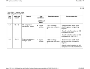
VAG1598/11 adapter cable
LED voltage tester US 1115
Test
step VAG1598
socket Test of
Test
conditions
- additional
steps Specified values
Corrective action
5.8 13 + 12 "AC compressor
intervention" output
Engine
running - LED in voltage
tester does not come
on - Determine and rectify short
circuit to ground using wiring
diagram.
- Rectify cut-off condition for A/C
compressor in ECM.
- Rectify cut-off condition for A/C
compressor in TCM -J217-.
5.9 13 + 51 "Engine temperature
too high" signal Engine
running - LED in voltage
tester does not come
on - Determine and rectify short
circuit to ground using wiring
diagram.
- Rectify cut-off condition for A/C
compressor in Instrument Cluster.
Pa
ge 22 of 47 A/C s
ystem, electrical testin
g
11/21/2002 htt
p://127.0.0.1:8080/audi/servlet/Dis
play?action=Goto&t
yp
e=re
pair&id=AUDI.B5.HA01.01.2
Page 23 of 47
01-133
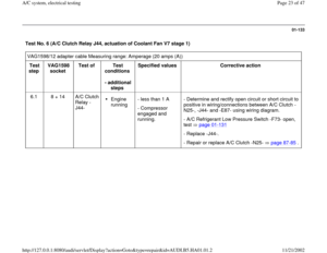
Test No. 6 (A/C Clutch Relay J44, actuation of Coolant Fan V7 stage 1) VAG1598/12 adapter cable Measuring range: Amperage (20 amps (A))
Test
step VAG1598
socket Test of
Test
conditions
- additional
steps Specified values
Corrective action
6.1 8 + 14 A/C Clutch
Relay -
J44-
Engine
running - less than 1 A
- Compressor
engaged and
running. - Determine and rectify open circuit or short circuit to
positive in wiring/connections between A/C Clutch -
N25-, -J44- and -E87- using wiring diagram.
- A/C Refrigerant Low Pressure Switch -F73- open,
test page 01
-131
- Replace -J44-.
- Repair or replace A/C Clutch -N25- page 87
-85
.
Pa
ge 23 of 47 A/C s
ystem, electrical testin
g
11/21/2002 htt
p://127.0.0.1:8080/audi/servlet/Dis
play?action=Goto&t
yp
e=re
pair&id=AUDI.B5.HA01.01.2
Page 24 of 47
01-134
VAG1598/12 adapter cable Measuring range: Amperage (20 amps (A))
Test
step VAG1598
socket Test of
Test
conditions
- additional
steps Specified
values Corrective action
6.2 16 + 14 Control of Coolant Fan
control (FC) relay -J26- (for
stage 1 operation of
Coolant Fan -V7-)
Engine
running - less than
1 A
- Fan runs
in stage 1. - Determine and rectify open circuit or short
circuit to positive in wiring/connections
between -J26- and -E87- using wiring
diagram.
- Check -V7- Repair Group 19
Note:
Testing operation of coolant fan via refrigerant high pressure switch F23 page 87
-64
.
Pa
ge 24 of 47 A/C s
ystem, electrical testin
g
11/21/2002 htt
p://127.0.0.1:8080/audi/servlet/Dis
play?action=Goto&t
yp
e=re
pair&id=AUDI.B5.HA01.01.2


Test
step VAG1598
socket Test of
Test
conditions
- additional
steps Specified
values Corrective actio")

Test
step VAG1598
socket Test of
Test
conditions
- additional
steps Specified
values Corrective actio")

 VAG1598/12 adapter cable Measuring range: Amperage (20 amps (A))
Test
step VAG1598
socket Test of
Test
conditio")
)
Test
step VAG1598
socket Test of
Test
conditions
- additional
steps Specified
values Corrective action
6.2")