LOWER SUSPENSION ARM AND STRUT
ROD REMOVAL
Installation is in the reverse order of removal.
INSTALLATION HINT: After installation, check ABS speed
sensor signal and rear wheel alignment.
(See page BR±62 and SA±9)
1. REMOVE REAR WHEEL
Torque: 103 NVm (1,050 kgfVcm, 76 ftVlbf)
2. REMOVE REAR DRIVE SHAFT
(See page SA±46)
3. REMOVE REAR BRAKE CALIPER
(a) Remove the 2 bolts and brake caliper from the rear axle
carrier.
Torque: 104 NVm (1,065 kgfVcm, 77 ftVlbf)
(b) Support the brake caliper securely.
4. REMOVE STRUT ROD
Remove the 2 bolts, nuts and strut rod.
Torque: 184 NVm (1,880 kgfVcm, 134 ftVlbf)
INSTALLATION HINT: After stabilizing the suspension,
torque the bolts.
5. REMOVE LOWER SUSPENSION ARM NO.1
(a) Remove the nut.
Torque: 59 NVm (600 kgfVcm, 43 ftVlbf)
(b) Using SST, disconnect the lower suspension arm No.1 from
the rear axle carrier.
SST 09610±20012
NOTICE: Be careful not to damage the dust boot.
(c) Remove the bolt and disconnect the parking brake cable
bracket.
(d) Place matchmarks on the adjusting cam and subframe.
(e) Remove the adjusting cam and nut.
Torque: 184 NVm (1,880 kgfVcm, 134 ftVlbf)
INSTALLATION HINT: After stabilizing the suspension,
torque the nut.
(f) Remove the lower suspension arm No.1.
± SUSPENSION AND AXLEREAR SUSPENSIONSA±93
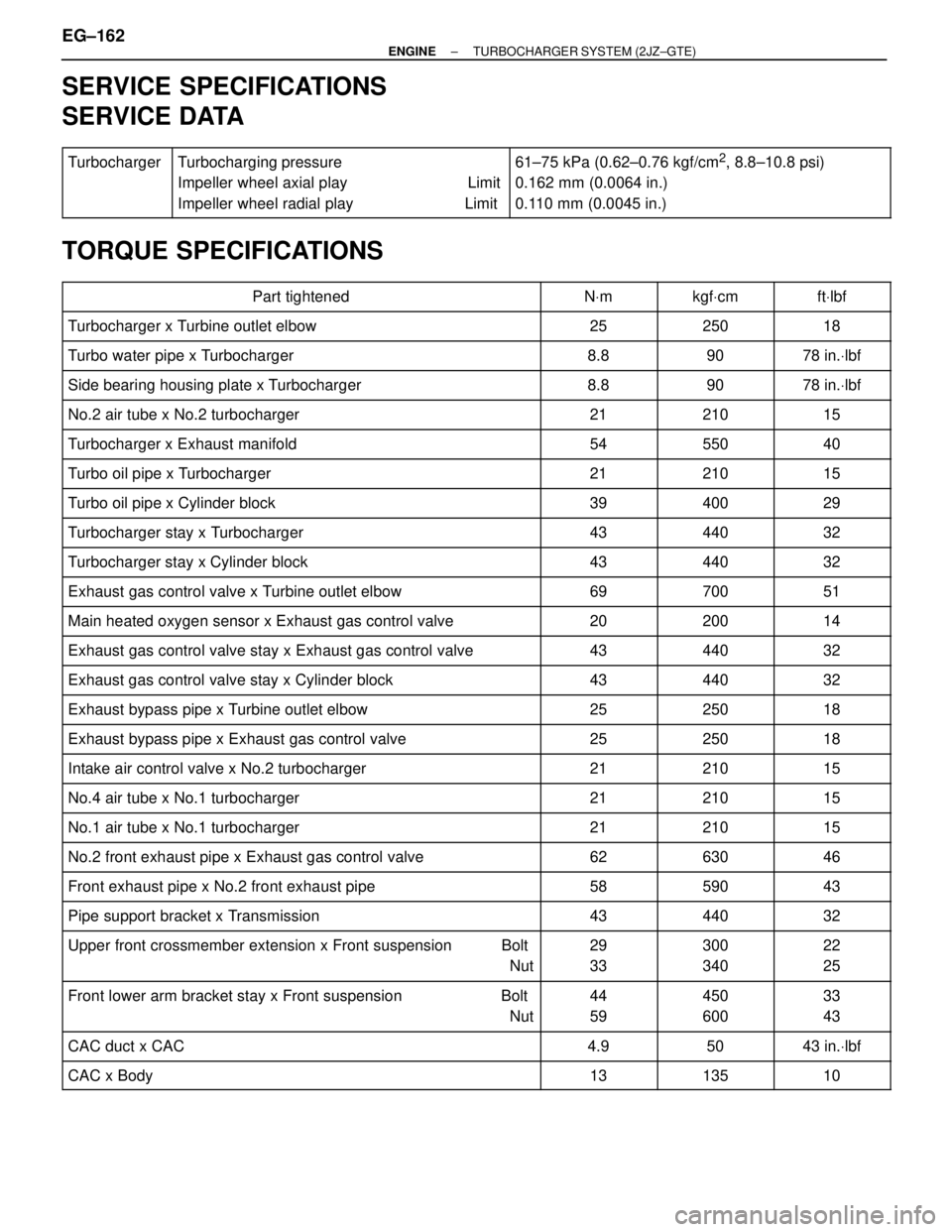
SERVICE SPECIFICATIONS
SERVICE DATA
������ �
����� �
����� ������
Turbocharger��������������� �
�������������� �
�������������� ���������������
Turbocharging pressure
Impeller wheel axial play Limit
Impeller wheel radial play Limit����������������� �
���������������� �
���������������� �����������������
61±75 kPa (0.62±0.76 kgf/cm2, 8.8±10.8 psi)
0.162 mm (0.0064 in.)
0.110 mm (0.0045 in.)
TORQUE SPECIFICATIONS
��������������������� �
�������������������� ���������������������Part tightened������ �
����� ������NVm������ �
����� ������kgfVcm������ �
����� ������ftVlbf
��������������������� ���������������������Turbocharger x Turbine outlet elbow������ ������25������ ������250������ ������18
��������������������� ���������������������Turbo water pipe x Turbocharger������ ������8.8������ ������90������ ������78 in.Vlbf
��������������������� ���������������������Side bearing housing plate x Turbocharger������ ������8.8������ ������90������ ������78 in.Vlbf
��������������������� ���������������������No.2 air tube x No.2 turbocharger������ ������21������ ������210������ ������15��������������������� �
�������������������� ���������������������Turbocharger x Exhaust manifold
������ �
����� ������54
������ �
����� ������550
������ �
����� ������40
��������������������� ���������������������Turbo oil pipe x Turbocharger������ ������21������ ������210������ ������15
��������������������� ���������������������Turbo oil pipe x Cylinder block������ ������39������ ������400������ ������29
��������������������� ���������������������Turbocharger stay x Turbocharger������ ������43������ ������440������ ������32��������������������� �
�������������������� ���������������������Turbocharger stay x Cylinder block
������ �
����� ������43
������ �
����� ������440
������ �
����� ������32
��������������������� ���������������������Exhaust gas control valve x Turbine outlet elbow������ ������69������ ������700������ ������51
��������������������� ���������������������Main heated oxygen sensor x Exhaust gas control valve������ ������20������ ������200������ ������14
��������������������� ���������������������Exhaust gas control valve stay x Exhaust gas control valve������ ������43������ ������440������ ������32��������������������� �
�������������������� ���������������������Exhaust gas control valve stay x Cylinder block
������ �
����� ������43
������ �
����� ������440
������ �
����� ������32
��������������������� ���������������������Exhaust bypass pipe x Turbine outlet elbow������ ������25������ ������250������ ������18
��������������������� ���������������������Exhaust bypass pipe x Exhaust gas control valve������ ������25������ ������250������ ������18
��������������������� ���������������������Intake air control valve x No.2 turbocharger������ ������21������ ������210������ ������15��������������������� �
��������������������No.4 air tube x No.1 turbocharger������ �
�����21������ �
�����210������ �
�����15��������������������� �
�������������������� ���������������������No.1 air tube x No.1 turbocharger
������ �
����� ������21
������ �
����� ������210
������ �
����� ������15
��������������������� ���������������������No.2 front exhaust pipe x Exhaust gas control valve������ ������62������ ������630������ ������46
��������������������� ���������������������Front exhaust pipe x No.2 front exhaust pipe������ ������58������ ������590������ ������43
��������������������� ���������������������Pipe support bracket x Transmission������ ������43������ ������440������ ������32��������������������� �
�������������������� �
�������������������� ���������������������
Upper front crossmember extension x Front suspension Bolt
Nut
������ �
����� �
����� ������
29
33
������ �
����� �
����� ������
300
340
������ �
����� �
����� ������
22
25
��������������������� �
�������������������� ���������������������
Front lower arm bracket stay x Front suspension Bolt
Nut������ �
����� ������
44
59������ �
����� ������
450
600������ �
����� ������
33
43
��������������������� ���������������������CAC duct x CAC������ ������4.9������ ������50������ ������43 in.Vlbf
��������������������� ���������������������CAC x Body������ ������13������ ������135������ ������10
EG±162± ENGINETURBOCHARGER SYSTEM (2JZ±GTE)