Page 1299 of 2543
(d) Install the assembly on the output shaft with the synchronizer
ring slots aligned with the shifting keys and turn the inner race
to align it with the locking ball.
8. INSTALL OUTPUT SHAFT CENTER BEARING
Using SST and a press, install the bearing on the output shaft
with the outer race snap ring groove toward the rear.
HINT: Hold the 1st gear inner race to prevent it from falling.
SST 09506±35010
9. INSPECT 1ST GEAR THRUST CLEARANCE
Using a feeler gauge, measure the 1st gear thrust clearance.
Standard clearance:
0.10±0.25 mm (0.0039±0.0098 in.)
± W58 MANUAL TRANSMISSIONOUTPUT SHAFTMT1±33
Page 1300 of 2543
COUNTER GEAR AND REVERSE
IDLER GEAR
COMPONENTS
COUNTER GEAR COMPONENT PARTS
DISASSEMBLY
REMOVE NO.3 HUB SLEEVE, SHIFTING KEYS AND
SPRINGS FROM SYNCHRONIZER RING
(a) Remove the synchronizer ring assembly from the No.3 hub
sleeve.
(b) Turn the reverse synchronizer pull ring. MT1±34
± W58 MANUAL TRANSMISSIONCOUNTER GEAR AND REVERSE IDLER GEAR
Page 1301 of 2543
(c) Remove the reverse synchronizer ring and 5th synchronizer
ring from the synchronizer pull ring and cone ring.
(d) Turn the reverse synchronizer pull ring, separate the pull ring
and cone ring.
(e) While pushing the shifting key spring to out slide with 2
screwdrivers, remove the 3 shifting keys and key springs,
from the reverse synchronizer ring.
COUNTER GEAR AND REVERSE IDLER
GEAR COMPONENT PARTS
INSPECTION
1. INSPECT COUNTER 5 TH GEAR RADIAL CLEARANCE
(a) Install the spacer, counter 5th gear and needle roller bearing
to the counter gear.
(b) Using a dial indicator, measure the counter 5th gear radial
clearance.
Standard clearance:
0.009±0.060 mm (0.0004±0.0024 in.)
Maximum clearance:
0.150 mm (0.0059 in.)
If the clearance exceeds the maximum, replace the counter
gear or needle roller bearing or counter 5th gear.
± W58 MANUAL TRANSMISSIONCOUNTER GEAR AND REVERSE IDLER GEARMT1±35
Page 1304 of 2543
2. IF NECESSARY, REPLACE COUNTER GEAR CENTER
BEARING
(a) Remove the bearing from the counter gear.
(b) Install a new bearing on the counter gear.
HINT: Engage the roller cages.
(c) Using SST, tap out the bearing outer race.
SST 09608±35014 (09608±06020, 09608±06090)
HINT: The outer race will be installed later, as the transmis-
sion is assembled.
COUNTER GEAR ASSEMBLY
INSTALL SYNCHRONIZER RING ASSEMBLY TO NO.3
HUB SLEEVE
(a) Push the synchronizer key spring, install the shifting key and
key spring to the reverse synchronizer ring.
(b) Usin g a scre wd rive r, pu sh th e 3 ke y sp rin g s in to th e
synchronizer ring spring gaps.
(c) Install the synchronizer cone ring to the reverse synchronizer
pull ring and turn the pull ring. MT1±38
± W58 MANUAL TRANSMISSIONCOUNTER GEAR AND REVERSE IDLER GEAR
Page 1305 of 2543
(d) Install the 5th synchronizer ring.
(e) Install the reverse synchronizer ring.
(f) Turn the reverse synchronizer pull ring.
(g) While pushing 3 shifting keys, install the synchronizer ring
assembly to the No.3 hub sleeve.
± W58 MANUAL TRANSMISSIONCOUNTER GEAR AND REVERSE IDLER GEARMT1±39
Page 1343 of 2543

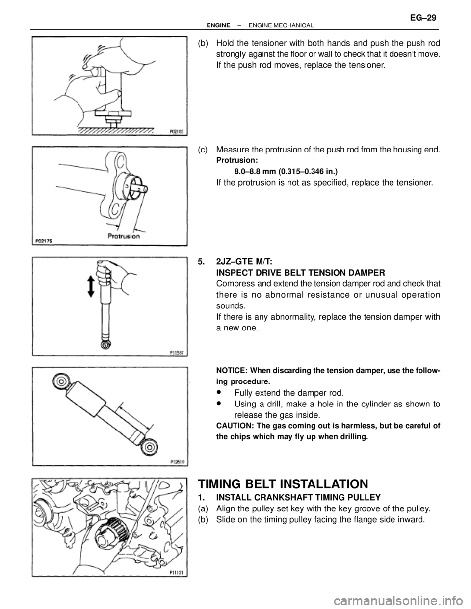
(b) Hold the tensioner with both hands and push the push rod
strongly against the floor or wall to check that it doesn't move.
If the push rod moves, replace the tensioner.
(c) Measure the protrusion of the push rod from the housing end.
Protrusion:
8.0±8.8 mm (0.315±0.346 in.)
If the protrusion is not as specified, replace the tensioner.
5. 2JZ±GTE M/T:
INSPECT DRIVE BELT TENSION DAMPER
Compress and extend the tension damper rod and check that
there is no abnormal resistance or unusual operation
sounds.
If there is any abnormality, replace the tension damper with
a new one.
NOTICE: When discarding the tension damper, use the follow-
ing procedure.
wFully extend the damper rod.
wUsing a drill, make a hole in the cylinder as shown to
release the gas inside.
CAUTION: The gas coming out is harmless, but be careful of
the chips which may fly up when drilling.
TIMING BELT INSTALLATION
1. INSTALL CRANKSHAFT TIMING PULLEY
(a) Align the pulley set key with the key groove of the pulley.
(b) Slide on the timing pulley facing the flange side inward.
± ENGINEENGINE MECHANICALEG±29
Page 1345 of 2543

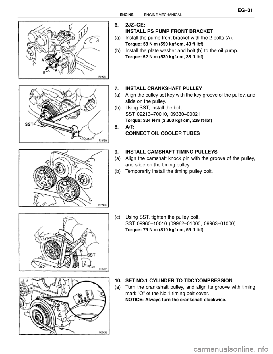
6. 2JZ±GE:
INSTALL PS PUMP FRONT BRACKET
(a) Install the pump front bracket with the 2 bolts (A).
Torque: 58 NVm (590 kgfVcm, 43 ftVlbf)
(b) Install the plate washer and bolt (b) to the oil pump.
Torque: 52 NVm (530 kgfVcm, 38 ftVlbf)
7. INSTALL CRANKSHAFT PULLEY
(a) Align the pulley set key with the key groove of the pulley, and
slide on the pulley.
(b) Using SST, install the bolt.
SST 09213±70010, 09330±00021
Torque: 324 NVm (3,300 kgfVcm, 239 ftVlbf)
8. A/T:
CONNECT OIL COOLER TUBES
9. INSTALL CAMSHAFT TIMING PULLEYS
(a) Align the camshaft knock pin with the groove of the pulley,
and slide on the timing pulley.
(b) Temporarily install the timing pulley bolt.
(c) Using SST, tighten the pulley bolt.
SST 09960±10010 (09962±01000, 09963±01000)
Torque: 79 NVm (810 kgfVcm, 59 ftVlbf)
10. SET NO.1 CYLINDER TO TDC/COMPRESSION
(a) Turn the crankshaft pulley, and align its groove with timing
mark ºOº of the No.1 timing belt cover.
NOTICE: Always turn the crankshaft clockwise.
± ENGINEENGINE MECHANICALEG±31
Page 1646 of 2543

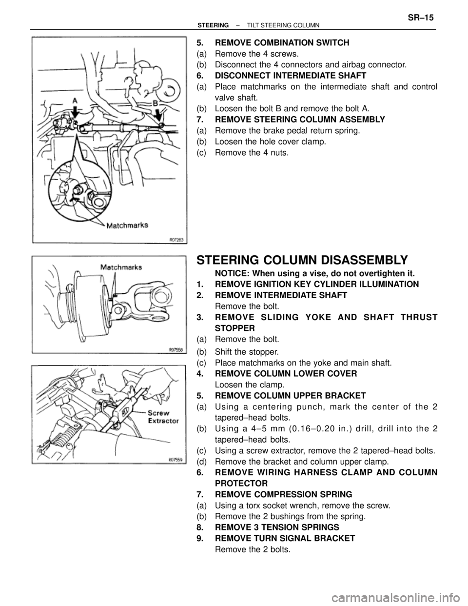
5. REMOVE COMBINATION SWITCH
(a) Remove the 4 screws.
(b) Disconnect the 4 connectors and airbag connector.
6. DISCONNECT INTERMEDIATE SHAFT
(a) Place matchmarks on the intermediate shaft and control
valve shaft.
(b) Loosen the bolt B and remove the bolt A.
7. REMOVE STEERING COLUMN ASSEMBLY
(a) Remove the brake pedal return spring.
(b) Loosen the hole cover clamp.
(c) Remove the 4 nuts.
STEERING COLUMN DISASSEMBLY
NOTICE: When using a vise, do not overtighten it.
1. REMOVE IGNITION KEY CYLINDER ILLUMINATION
2. REMOVE INTERMEDIATE SHAFT
Remove the bolt.
3. REMOVE SLIDING YOKE AND SHAFT THRUST
STOPPER
(a) Remove the bolt.
(b) Shift the stopper.
(c) Place matchmarks on the yoke and main shaft.
4. REMOVE COLUMN LOWER COVER
Loosen the clamp.
5. REMOVE COLUMN UPPER BRACKET
(a) U s i n g a c e n t e r i n g p u n c h , m a r k t h e c e n t e r o f t h e 2
tapered±head bolts.
(b) U s i n g a 4 ± 5 m m ( 0 .16±0.20 in.) drill, drill into the 2
tapered±head bolts.
(c) Using a screw extractor, remove the 2 tapered±head bolts.
(d) Remove the bracket and column upper clamp.
6. REMOVE WIRING HARNESS CLAMP AND COLUMN
PROTECTOR
7. REMOVE COMPRESSION SPRING
(a) Using a torx socket wrench, remove the screw.
(b) Remove the 2 bushings from the spring.
8. REMOVE 3 TENSION SPRINGS
9. REMOVE TURN SIGNAL BRACKET
Remove the 2 bolts.
± STEERINGTILT STEERING COLUMNSR±15