Page 740 of 2543
Taillight Control Relay Circuit
CIRCUIT DESCRIPTION
When the theft deterrent system is activated, it causes the Tr in the ECU to switch on and off at approximately
0.2 sec. intervals. This switches the taillight control relay on and off, thus flashing the taillights (See the wiring
diagram below).
In this condition, if any of the following operations is done, the Tr in the ECU goes off and the taillight control
relay switches off, thus stopping the taillights flashing:
(1) The front LH or RH door is unlocked with a key.
(2) The ignition switch is turned to ACC or ON position.
(3) Approximately 1 minute elapses.
BE±138± BODY ELECTRICAL SYSTEMTHEFT DETERRENT AND DOOR LOCK CONTROL SYSTEM
Page 875 of 2543

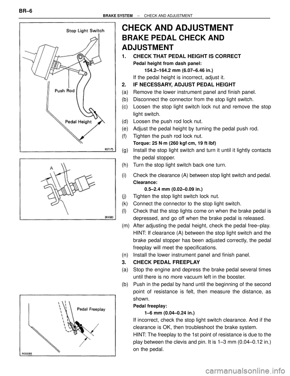
CHECK AND ADJUSTMENT
BRAKE PEDAL CHECK AND
ADJUSTMENT
1. CHECK THAT PEDAL HEIGHT IS CORRECT
Pedal height from dash panel:
154.2±164.2 mm (6.07±6.46 in.)
If the pedal height is incorrect, adjust it.
2. IF NECESSARY, ADJUST PEDAL HEIGHT
(a) Remove the lower instrument panel and finish panel.
(b) Disconnect the connector from the stop light switch.
(c) Loosen the stop light switch lock nut and remove the stop
light switch.
(d) Loosen the push rod lock nut.
(e) Adjust the pedal height by turning the pedal push rod.
(f) Tighten the push rod lock nut.
Torque: 25 NVm (260 kgfVcm, 19 ftVlbf)
(g) Install the stop light switch and turn it until it lightly contacts
the pedal stopper.
(h) Turn the stop light switch back one turn.
(i) Check the clearance (A) between stop light switch and pedal.
Clearance:
0.5±2.4 mm (0.02±0.09 in.)
(j) Tighten the stop light switch lock nut.
(k) Connect the connector to the stop light switch.
(l) Check that the stop lights come on when the brake pedal is
depressed, and go off when the brake pedal is released.
(m) After adjusting the pedal height, check the pedal free±play.
HINT: If clearance (A) between the stop light switch and the
brake pedal stopper has been adjusted correctly, the pedal
freeplay will meet the specifications.
(n) Install the lower instrument panel and finish panel.
3. CHECK PEDAL FREEPLAY
(a) Stop the engine and depress the brake pedal several times
until there is no more vacuum left in the booster.
(b) Push in the pedal by hand until the beginning of the second
point of resistance is felt, then measure the distance, as
shown.
Pedal freeplay:
1±6 mm (0.04±0.24 in.)
If incorrect, check the stop light switch clearance. And if the
clearance is OK, then troubleshoot the brake system.
HINT: The freeplay to the 1st point of resistance is due to the
play between the clevis and pin. It is 1±3 mm (0.04±0.12 in.)
on the pedal. BR±6
± BRAKE SYSTEMCHECK AND ADJUSTMENT
Page 975 of 2543
INSPECTION PROCEDURE
Remove ABS & TRAC ECU with connectors still
connected.
Measure voltage between terminals STP of ABS
(& TRAC) ECU and body ground when brake ped-
al is depressed
Voltage: 8 Ð 14 V
Check operation of stop light.
Check voltage between terminal STP of ABS (& TRAC) ECU and
body ground.
Remove ABS & TRAC ECU with connectors
still connected.
Measure voltage between terminals STP of
ABS (& TRAC) ECU and body ground when
brake pedal is depressed.
Voltage: 8 Ð 14 V
Repair stop light circuit.
Repair or replace harness or connector.
Proceed to next circuit inspection shown on
problem symptoms chart (See page BR±64).
Check for open in harness and connector between ABS (& TRAC)
ECU and stop light switch (See page IN±30).
Check and replace ABS (& TRAC) ECU.
Check the stop light lights up when brake pedal is depressed and turns off when brake pedal is
released. BR±106
± BRAKE SYSTEMANTI±LOCK BRAKE SYSTEM (ABS)
Page 976 of 2543
ABS Warning Light Circuit
CIRCUIT DESCRIPTION
If the ECU detects trouble, it lights the ABS warning light while at the same time prohibiting ABS control.
At this time, the ECU records a diagnostic trouble code in memory.
After removing the short pin of the DLC1, connect terminals Tc and E1 of the DLC1 or DLC2 to make the
ABS warning light to blink and output the diagnostic trouble code.
± BRAKE SYSTEMANTI±LOCK BRAKE SYSTEM (ABS)BR±107
Page 997 of 2543

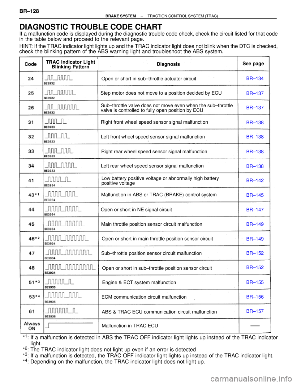
BR±134
BR±137
BR±137
BR±138
BR±138
BR±138
BR±138
BR±142
BR±145
BR±147
BR±149
BR±149
BR±152
BR±152
BR±155
BR±156
BR±157
Open or short in sub±throttle actuator circuit
Step motor does not move to a position decided by ECU
Sub±throttle valve does not move even when the sub±throttle
valve is controlled to fully open position by ECU
Right front wheel speed sensor signal malfunction
Left front wheel speed sensor signal malfunction
Right rear wheel speed sensor signal malfunction
Left rear wheel speed sensor signal malfunction
Low battery positive voltage or abnormally high battery
positive voltage
Malfunction in ABS or TRAC (BRAKE) control system
Open or short in NE signal circuit
Main throttle position sensor circuit malfunction
Open or short in main throttle position sensor circuit
Sub±throttle position sensor circuit malfunction
Open or short in sub±throttle position sensor circuit
Engine & ECT system malfunction
ECM communication circuit malfunction
ABS & TRAC ECU communication circuit malfunction
Malfunction in TRAC ECU
DiagnosisCodeTRAC Indicator Light
Blinking PatternSee page
DIAGNOSTIC TROUBLE CODE CHART
If a malfunction code is displayed during the diagnostic trouble code check, check the circuit listed for that code
in the table below and proceed to the relevant page.
HINT: If the TRAC indicator light lights up and the TRAC indicator light does not blink when the DTC is checked,
check the blinking pattern of the ABS warning light and troubleshoot the ABS system.
*
1: If a malfunction is detected in ABS the TRAC OFF indicator light lights up instead of the TRAC indicator
light.
*
2: The TRAC indicator light does not light up even if an error is detected
*3: If a malfunction is detected, the TRAC OFF indicator light lights up instead of the TRAC indicator light.
*4: Depending on the malfunction, the TRAC indicator light does not light up. BR±128
± BRAKE SYSTEMTRACTION CONTROL SYSTEM (TRAC)
Page 1028 of 2543
TRAC OFF Indicator TRAC Cut Switch Circuit
CIRCUIT DESCRIPTION
This is the TRAC control main switch. When the TRAC cut switch is pushed on, TRAC control goes off and the
TRAC OFF indicator lights up. This indicator is also used for warnings when the trouble occurs.
± BRAKE SYSTEMTRACTION CONTROL SYSTEM (TRAC)BR±159
Page 1043 of 2543

wConnect the positive (+) probe of the ammeter to
terminal B of the generator.
wConnect the positive (+) probe of the voltmeter to
terminal B of the generator.
wGround the negative (±) probe of the voltmeter.
(b) Check the charging circuit as follows:
With the engine running from idling to 2,000 rpm, check the
reading on the ammeter and voltmeter:
Standard amperage:
10 A or less
Standard voltage:
At 25°C (77°F)
13.6±14.8 V
At 115°C (239°F)
S13.2±14.0 V
If the voltmeter reading is more than standard voltage, re-
place the voltage regulator.
If the voltmeter reading is less than standard voltage, check
the voltage regulator and generator as follows:
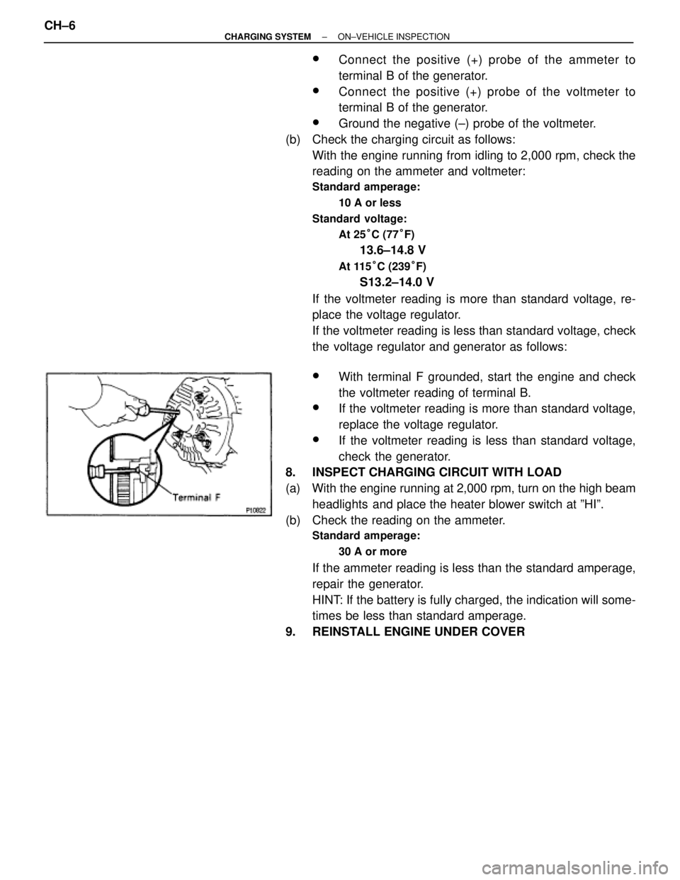
wWith terminal F grounded, start the engine and check
the voltmeter reading of terminal B.
wIf the voltmeter reading is more than standard voltage,
replace the voltage regulator.
wIf the voltmeter reading is less than standard voltage,
check the generator.
8. INSPECT CHARGING CIRCUIT WITH LOAD
(a) With the engine running at 2,000 rpm, turn on the high beam
headlights and place the heater blower switch at ºHIº.
(b) Check the reading on the ammeter.
Standard amperage:
30 A or more
If the ammeter reading is less than the standard amperage,
repair the generator.
HINT: If the battery is fully charged, the indication will some-
times be less than standard amperage.
9. REINSTALL ENGINE UNDER COVER CH±6
± CHARGING SYSTEMON±VEHICLE INSPECTION
Page 1192 of 2543

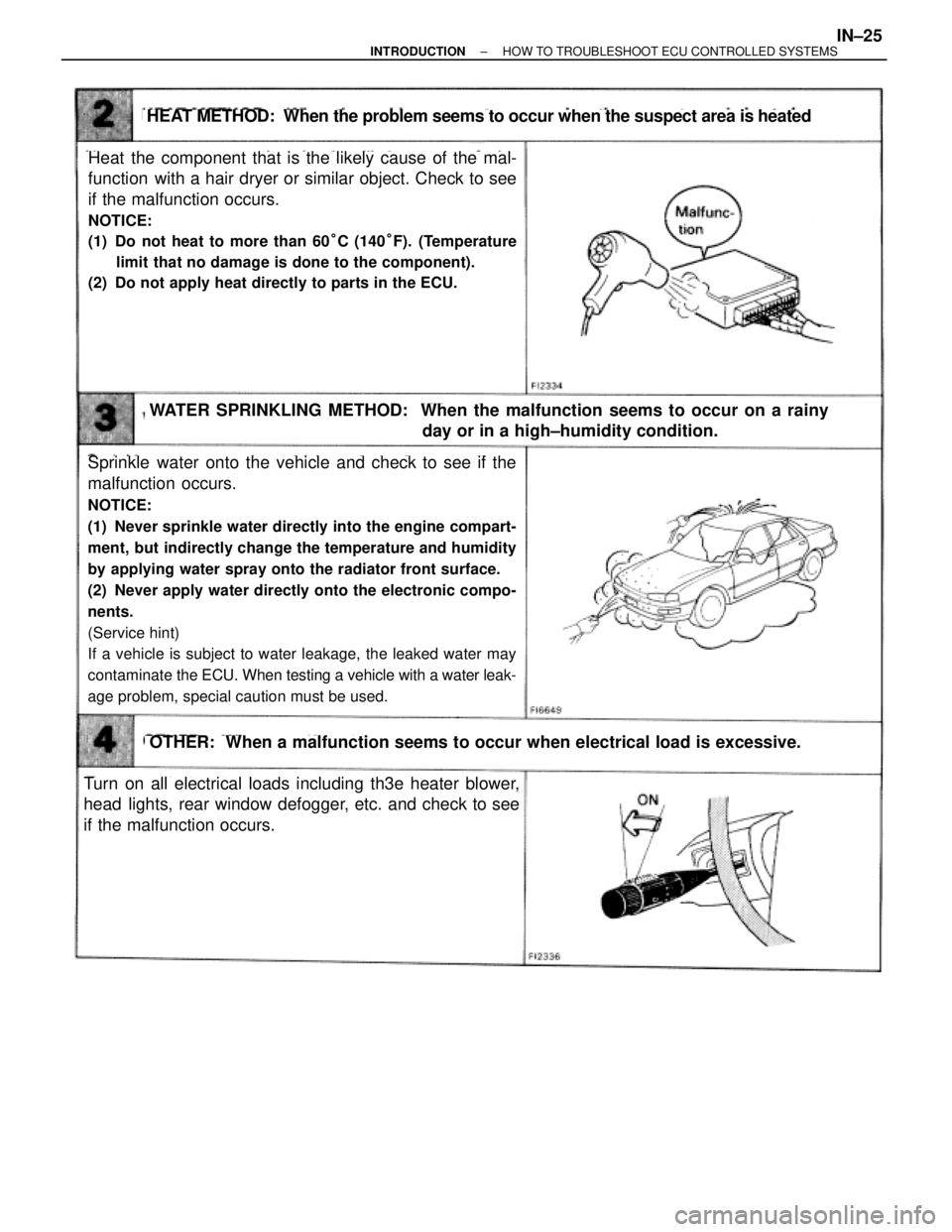
Heat the component that is the likely cause of the mal-
function with a hair dryer or similar object. Check to see
if the malfunction occurs.
NOTICE:
(1) Do not heat to more than 60°C (140°F). (Temperature
limit that no damage is done to the component).
(2) Do not apply heat directly to parts in the ECU.
HEAT METHOD: When the problem seems to occur when the suspect area is heated
WATER SPRINKLING METHOD: When the malfunction seems to occur on a rainy
day or in a high±humidity condition.
OTHER: When a malfunction seems to occur when electrical load is excessive.
Sprinkle water onto the vehicle and check to see if the
malfunction occurs.
NOTICE:
(1) Never sprinkle water directly into the engine compart-
ment, but indirectly change the temperature and humidity
by applying water spray onto the radiator front surface.
(2) Never apply water directly onto the electronic compo-
nents.
(Service hint)
If a vehicle is subject to water leakage, the leaked water may
contaminate the ECU. When testing a vehicle with a water leak-
age problem, special caution must be used.
Turn on all electrical loads including th3e heater blower,
head lights, rear window defogger, etc. and check to see
if the malfunction occurs.
± INTRODUCTIONHOW TO TROUBLESHOOT ECU CONTROLLED SYSTEMSIN±25