Page 1255 of 2543
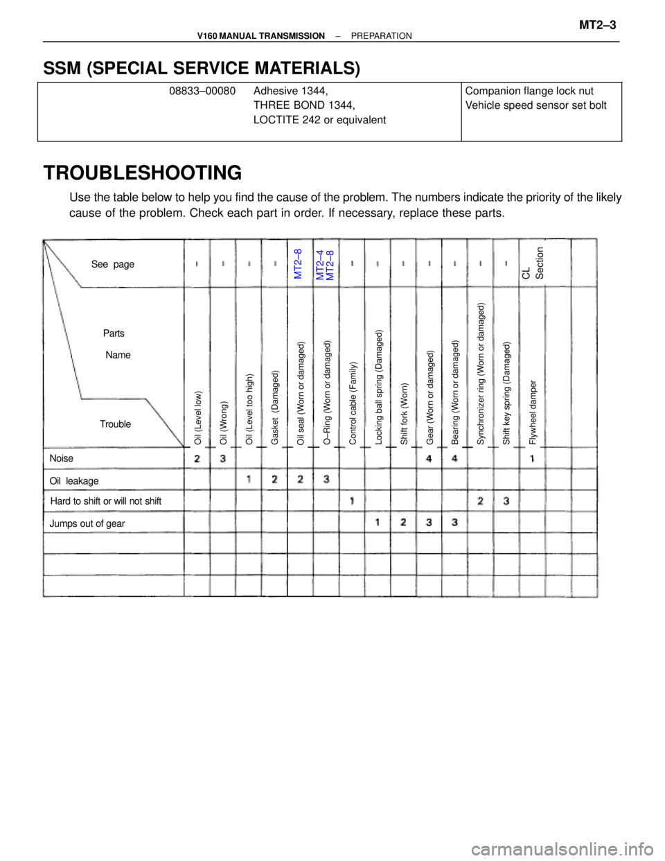
MT2±8MT2±4
Noise
Jumps out of gear
Trouble
Parts
Name
See page
Hard to shift or will not shift
Oil leakage
Oil (Level low)Oil seal (Worn or damaged)Gasket (Damaged)Oil (Level too high)Oil (Wrong)Locking ball spring (Damaged)Control cable (Family)Shift key spring (Damaged)O±Ring (Worn or damaged)Gear (Worn or damaged)Shift fork (Worn)Bearing (Worn or damaged)Synchronizer ring (Worn or damaged)Flywheel damper
MT2±8CL
Section
SSM (SPECIAL SERVICE MATERIALS)������������� �
������������ �
������������ �
������������ �������������
08833±00080
�������������� �
������������� �
������������� �
������������� ��������������
Adhesive 1344,
THREE BOND 1344,
LOCTITE 242 or equivalent
����������� �
���������� �
���������� �
���������� �����������
Companion flange lock nut
Vehicle speed sensor set bolt
TROUBLESHOOTING
Use the table below to help you find the cause of the problem. The numbers indicate the priority of the likely
cause of the problem. Check each part in order. If necessary, replace these parts.
± V160 MANUAL TRANSMISSIONPREPARATIONMT2±3
Page 1256 of 2543
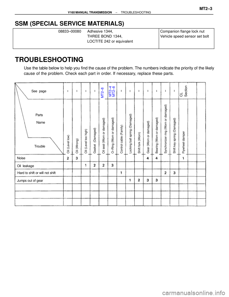
MT2±8MT2±4
Noise
Jumps out of gear
Trouble
Parts
Name
See page
Hard to shift or will not shift
Oil leakage
Oil (Level low)Oil seal (Worn or damaged)Gasket (Damaged)Oil (Level too high)Oil (Wrong)Locking ball spring (Damaged)Control cable (Family)Shift key spring (Damaged)O±Ring (Worn or damaged)Gear (Worn or damaged)Shift fork (Worn)Bearing (Worn or damaged)Synchronizer ring (Worn or damaged)Flywheel damper
MT2±8CL
Section
SSM (SPECIAL SERVICE MATERIALS)������������� �
������������ �
������������ �
������������ �������������
08833±00080
�������������� �
������������� �
������������� �
������������� ��������������
Adhesive 1344,
THREE BOND 1344,
LOCTITE 242 or equivalent
����������� �
���������� �
���������� �
���������� �����������
Companion flange lock nut
Vehicle speed sensor set bolt
TROUBLESHOOTING
Use the table below to help you find the cause of the problem. The numbers indicate the priority of the likely
cause of the problem. Check each part in order. If necessary, replace these parts.
± V160 MANUAL TRANSMISSIONTROUBLESHOOTINGMT2±3
Page 1271 of 2543
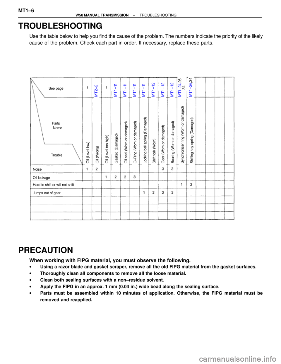
MT1±11MT1±26,34MT2±2MT1±24,26
34MT1±11MT1±11MT1±11MT1±12MT1±12MT1±12
Oil (Level low)O±Ring (Worn or damaged)Oil seal (Worn or damaged)Gasket (Damaged)Oil (Level too high)Oil (Wrong)Bearing (Worn or damaged)Gear (Worn or damaged)Shift fork (Worn)Locking ball spring (Damaged)O±Ring (Worn or damaged)Shifting key spring (Damaged)Synchronizer ring (Worn or damaged)
Noise
Jumps out of gear
Trouble
Parts
Name
See page
Hard to shift or will not shift
Oil leakage
TROUBLESHOOTING
Use the table below to help you find the cause of the problem. The numbers indicate the priority of the likely
cause of the problem. Check each part in order. If necessary, replace these parts.
PRECAUTION
When working with FIPG material, you must observe the following.
wUsing a razor blade and gasket scraper, remove all the old FIPG material from the gasket surfaces.
wThoroughly clean all components to remove all the loose material.
wClean both sealing surfaces with a non±residue solvent.
wApply the FIPG in an approx. 1 mm (0.04 in.) wide bead along the sealing surface.
wParts must be assembled within 10 minutes of application. Otherwise, the FIPG material must be
removed and reapplied.
MT1±6± W58 MANUAL TRANSMISSIONTROUBLESHOOTING
Page 1272 of 2543
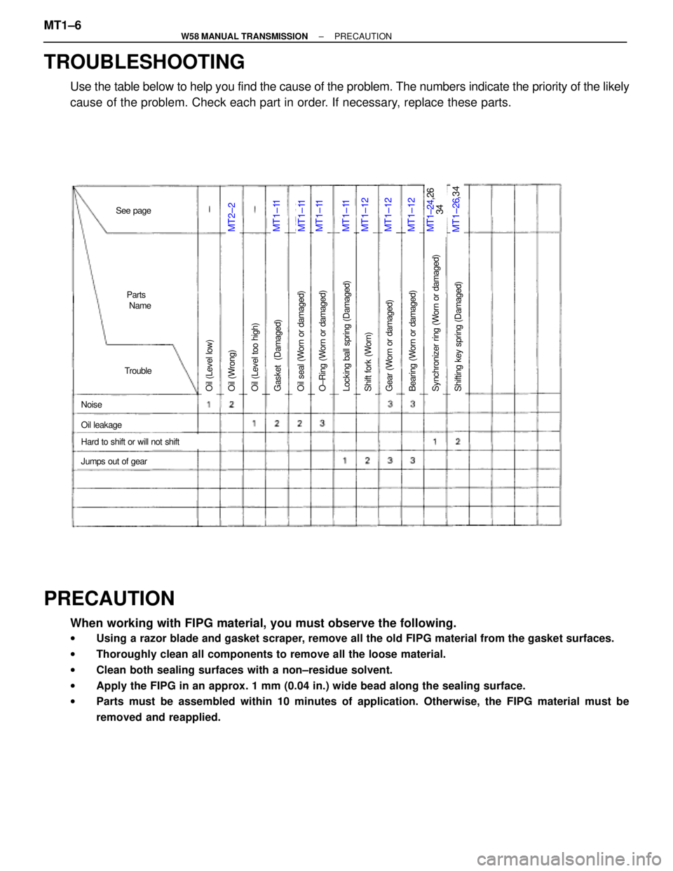
MT1±11MT1±26,34MT2±2MT1±24,26
34MT1±11MT1±11MT1±11MT1±12MT1±12MT1±12
Oil (Level low)O±Ring (Worn or damaged)Oil seal (Worn or damaged)Gasket (Damaged)Oil (Level too high)Oil (Wrong)Bearing (Worn or damaged)Gear (Worn or damaged)Shift fork (Worn)Locking ball spring (Damaged)O±Ring (Worn or damaged)Shifting key spring (Damaged)Synchronizer ring (Worn or damaged)
Noise
Jumps out of gear
Trouble
Parts
Name
Hard to shift or will not shift
Oil leakage
See page
TROUBLESHOOTING
Use the table below to help you find the cause of the problem. The numbers indicate the priority of the likely
cause of the problem. Check each part in order. If necessary, replace these parts.
PRECAUTION
When working with FIPG material, you must observe the following.
wUsing a razor blade and gasket scraper, remove all the old FIPG material from the gasket surfaces.
wThoroughly clean all components to remove all the loose material.
wClean both sealing surfaces with a non±residue solvent.
wApply the FIPG in an approx. 1 mm (0.04 in.) wide bead along the sealing surface.
wParts must be assembled within 10 minutes of application. Otherwise, the FIPG material must be
removed and reapplied.
MT1±6± W58 MANUAL TRANSMISSIONPRECAUTION
Page 1293 of 2543
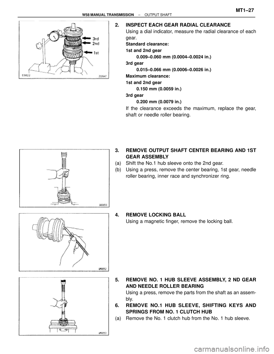
2. INSPECT EACH GEAR RADIAL CLEARANCE
Using a dial indicator, measure the radial clearance of each
gear.
Standard clearance:
1st and 2nd gear
0.009±0.060 mm (0.0004±0.0024 in.)
3rd gear
0.015±0.066 mm (0.0006±0.0026 in.)
Maximum clearance:
1st and 2nd gear
0.150 mm (0.0059 in.)
3rd gear
0.200 mm (0.0079 in.)
If the clearance exceeds the maximum, replace the gear,
shaft or needle roller bearing.
3. REMOVE OUTPUT SHAFT CENTER BEARING AND 1ST
GEAR ASSEMBLY
(a) Shift the No.1 hub sleeve onto the 2nd gear.
(b) Using a press, remove the center bearing, 1st gear, needle
roller bearing, inner race and synchronizer ring.
4. REMOVE LOCKING BALL
Using a magnetic finger, remove the locking ball.
5. REMOVE NO. 1 HUB SLEEVE ASSEMBLY, 2 ND GEAR
AND NEEDLE ROLLER BEARING
Using a press, remove the parts from the shaft as an assem-
bly.
6. REMOVE NO.1 HUB SLEEVE, SHIFTING KEYS AND
SPRINGS FROM NO. 1 CLUTCH HUB
(a) Remove the No. 1 clutch hub from the No. 1 hub sleeve.
± W58 MANUAL TRANSMISSIONOUTPUT SHAFTMT1±27
Page 1294 of 2543
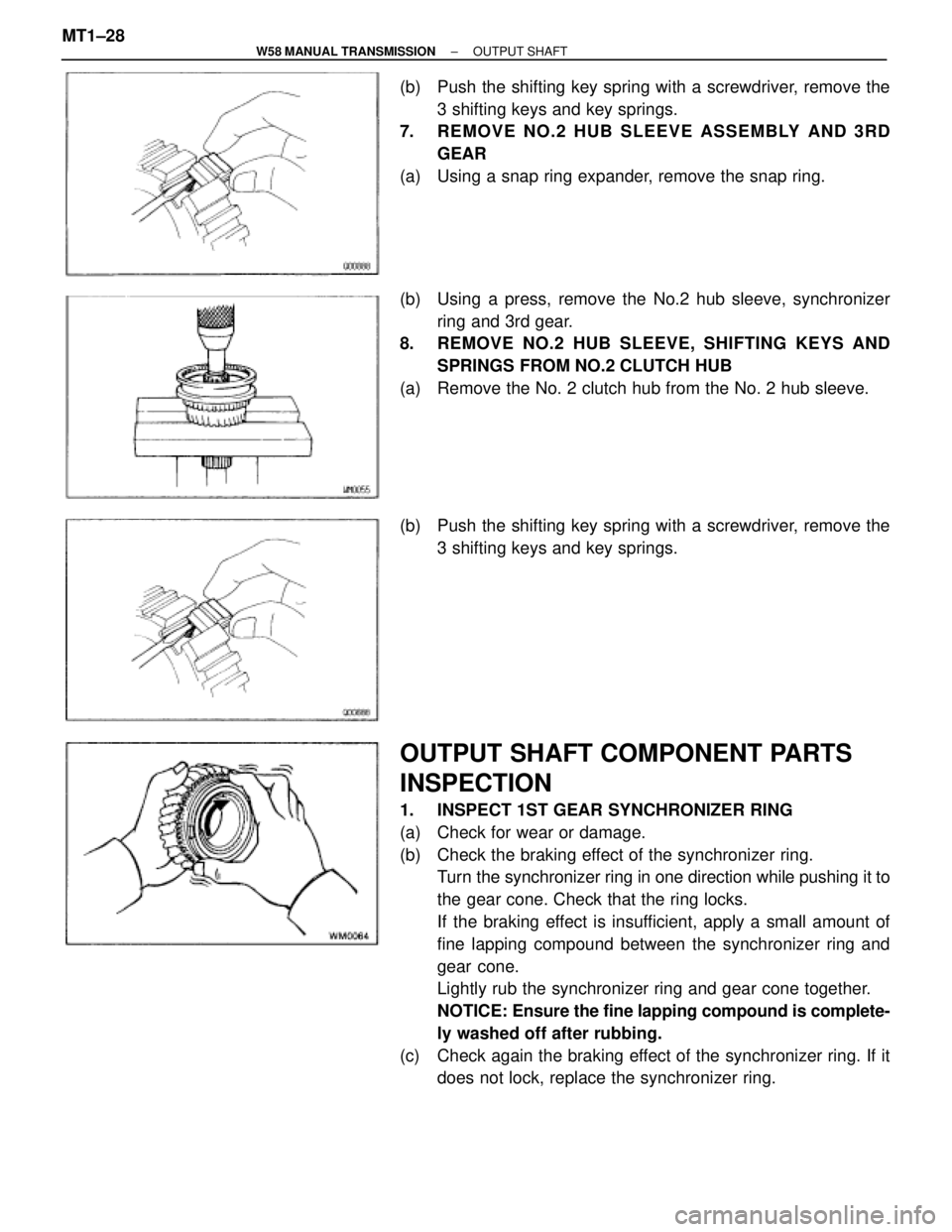
(b) Push the shifting key spring with a screwdriver, remove the
3 shifting keys and key springs.
7. REMOVE NO.2 HUB SLEEVE ASSEMBLY AND 3RD
GEAR
(a) Using a snap ring expander, remove the snap ring.
(b) Using a press, remove the No.2 hub sleeve, synchronizer
ring and 3rd gear.
8. REMOVE NO.2 HUB SLEEVE, SHIFTING KEYS AND
SPRINGS FROM NO.2 CLUTCH HUB
(a) Remove the No. 2 clutch hub from the No. 2 hub sleeve.
(b) Push the shifting key spring with a screwdriver, remove the
3 shifting keys and key springs.
OUTPUT SHAFT COMPONENT PARTS
INSPECTION
1. INSPECT 1ST GEAR SYNCHRONIZER RING
(a) Check for wear or damage.
(b) Check the braking effect of the synchronizer ring.
Turn the synchronizer ring in one direction while pushing it to
the gear cone. Check that the ring locks.
If the braking effect is insufficient, apply a small amount of
fine lapping compound between the synchronizer ring and
gear cone.
Lightly rub the synchronizer ring and gear cone together.
NOTICE: Ensure the fine lapping compound is complete-
ly washed off after rubbing.
(c) Check again the braking effect of the synchronizer ring. If it
does not lock, replace the synchronizer ring. MT1±28
± W58 MANUAL TRANSMISSIONOUTPUT SHAFT
Page 1297 of 2543
(e) Using a dial indicator, check the shaft runout.
Maximum runout:
0.06 mm (0.0024 in.)
If the runout exceeds the maximum, replace the output shaft.
OUTPUT SHAFT ASSEMBLY
HINT: Coat all of the sliding and rotating surface with gear oil
before assembly.
1. INSTALL NO.1 AND NO.2 CLUTCH HUB INTO HUB
SLEEVE
(a) Install the 3 shifting key springs to the clutch hub.
(b) While pushing the shifting key spring with a screw±driver,
install the 3 shifting keys.
(c) While pushing the 3 shifting keys, install the clutch hub to the
hub sleeve, as shown.
2. INSTALL 3RD GEAR AND NO.2 CLUTCH HUB ON
OUTPUT SHAFT
(a) Apply gear oil to the shaft.
(b) Place the synchronizer ring on the gear and align the ring
slots with the shifting keys.
± W58 MANUAL TRANSMISSIONOUTPUT SHAFTMT1±31
Page 1298 of 2543
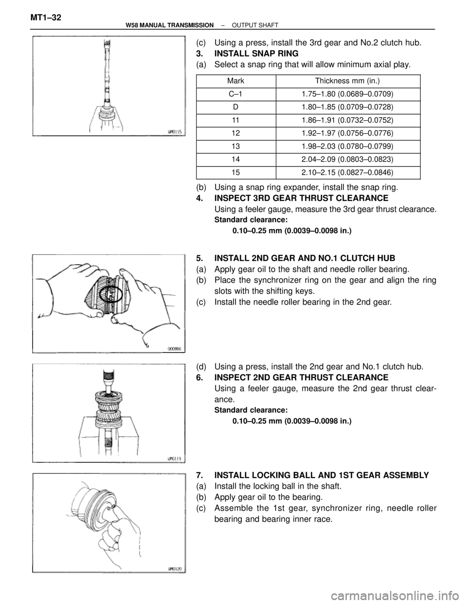
(c) Using a press, install the 3rd gear and No.2 clutch hub.
3. INSTALL SNAP RING
(a) Select a snap ring that will allow minimum axial play.
�������� ��������Mark������������� �������������Thickness mm (in.)
�������� ��������C±1������������� �������������1.75±1.80 (0.0689±0.0709)
�������� ��������D������������� �������������1.80±1.85 (0.0709±0.0728)
�������� ��������11������������� �������������1.86±1.91 (0.0732±0.0752)�������� ��������12������������� �������������1.92±1.97 (0.0756±0.0776)�������� �
������� ��������13
������������� �
������������ �������������1.98±2.03 (0.0780±0.0799)
�������� ��������14������������� �������������2.04±2.09 (0.0803±0.0823)
�������� ��������15������������� �������������2.10±2.15 (0.0827±0.0846)
(b) Using a snap ring expander, install the snap ring.
4. INSPECT 3RD GEAR THRUST CLEARANCE
Using a feeler gauge, measure the 3rd gear thrust clearance.
Standard clearance:
0.10±0.25 mm (0.0039±0.0098 in.)
5. INSTALL 2ND GEAR AND NO.1 CLUTCH HUB
(a) Apply gear oil to the shaft and needle roller bearing.
(b) Place the synchronizer ring on the gear and align the ring
slots with the shifting keys.
(c) Install the needle roller bearing in the 2nd gear.
(d) Using a press, install the 2nd gear and No.1 clutch hub.
6. INSPECT 2ND GEAR THRUST CLEARANCE
Using a feeler gauge, measure the 2nd gear thrust clear-
ance.
Standard clearance:
0.10±0.25 mm (0.0039±0.0098 in.)
7. INSTALL LOCKING BALL AND 1ST GEAR ASSEMBLY
(a) Install the locking ball in the shaft.
(b) Apply gear oil to the bearing.
(c) Assemble the 1st gear, synchronizer ring, needle roller
bearing and bearing inner race. MT1±32
± W58 MANUAL TRANSMISSIONOUTPUT SHAFT