Page 2092 of 2543
.
Disconnect solenoid resistor connector.
Measure resistance between terminals 1 and 2
~
4, 6 ~ 8 of solenoid resistor connector.
Resistance: Approx. 6 � at 20°C (68°F)
Check res")
(See page IN±30).
Disconnect solenoid resistor connector.
Measure resistance between terminals 1 and 2
~
4, 6 ~ 8 of solenoid resistor connector.
Resistance: Approx. 6 � at 20°C (68°F)
Check resistance between terminals 1 and 2 ~ 4, 6 ~ 8 of solenoid resistor
connector.
Check for open in harness and connector between terminal E01, E02 of ECM
connector and body ground (See page IN±30).
Disconnect injector connector.
See page EG±273)
Measure resistance of injector.
Resistance: Approx. 1.95 � at 20°C (68°F)
Check injection volume of injector.
(See page EG±279)
�Injection volume
124
~ cm3/15 sec.
(7.6 Ð 8.8 cu in./15 sec.)
Difference between each injector:
Less than 10 cm
3 (0.6 cu in.)
�Leakage
Fuel drop: One drop or less per minute
Replace solenoid resistor.
Check and repair harness and connector
between engine control module and battery.
Repair or replace harness or connector.
Replace injector.
Check and replace engine control module.
Check injectors.
Check and replace engine control module.
± ENGINE2JZ±GTE ENGINE TROUBLESHOOTINGEG±585
Page 2095 of 2543
INSPECTION PROCEDURE
(See page IN±30).
(See page EG±514).
Disconnect IAC valve connector.
Measure resistance between terminals shown be-
low.
Check IAC valve.
Check for open and short in harness and connector between EFI main relay
and IAC valve, IAC valve and engine control module (See page IN±30).
Repair or replace harness or connector.
Remove IAC Valve.
(1) Connect the battery positive lead to terminals
5 (B1) and 2 (B2), and the negative lead to ter±
minals 4(S1)Ð1(S2)Ð6(S3)Ð3(S4) in that or
der.
(2) Connect the battery positive lead to terminals
5 (B1) and 2 (B2) and the negative lead to ter±
minals 3(S4)Ð6(S3)Ð1(S2)Ð4(S1) in that or
der.
(1) The valve moves in the closing direction
(2) The valve moves in the opening direction.
Replace IAC valve.
Proceed to next circuit inspection shown on ma-
trix chart (See page EG±514).
TerminalResistance
EG±588± ENGINE2JZ±GTE ENGINE TROUBLESHOOTING
Page 2098 of 2543
INSPECTION PROCEDURE
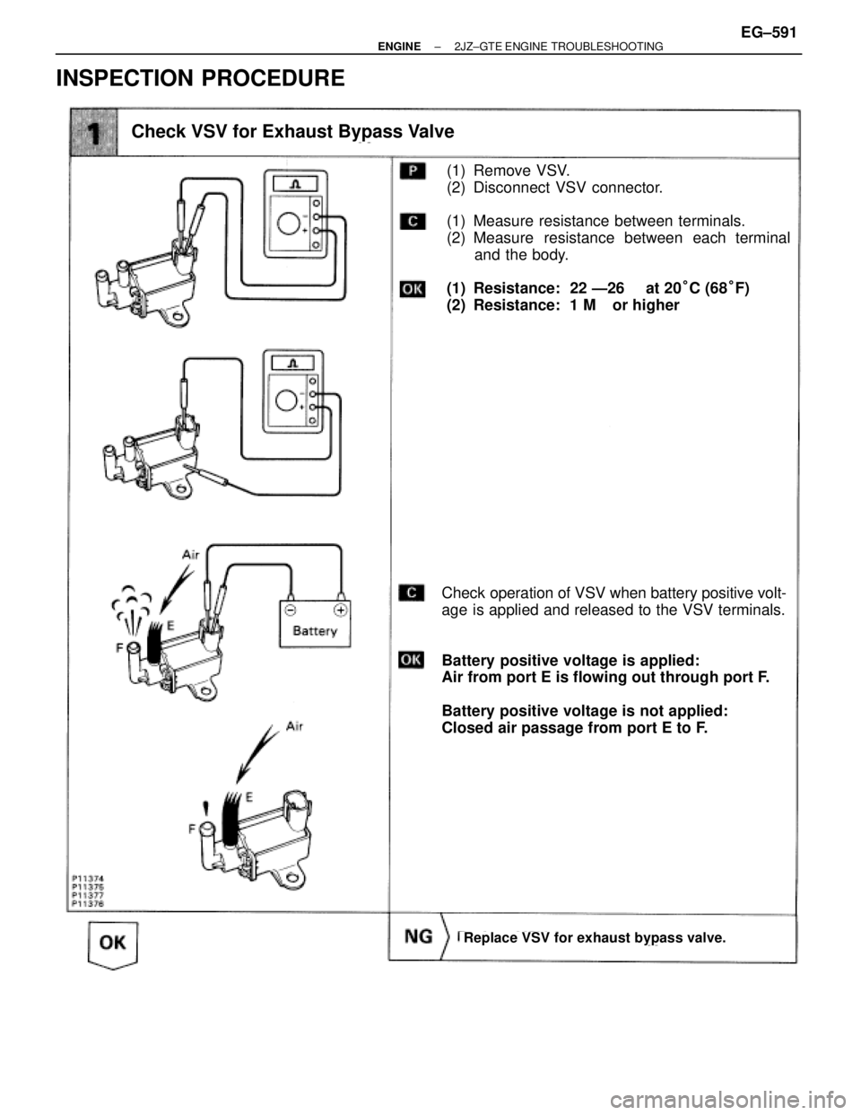
(1) Remove VSV.
(2) Disconnect VSV connector.
(1) Measure resistance between terminals.
(2) Measure resistance between each terminal
and the body.
(1) Resistance: 22 Ð26 � at 20°C (68°F)
(2) Resistance: 1 M� or higher
Check operation of VSV when battery positive volt-
age is applied and released to the VSV terminals.
Battery positive voltage is applied:
Air from port E is flowing out through port F.
Battery positive voltage is not applied:
Closed air passage from port E to F.
Check VSV for Exhaust Bypass Valve
Replace VSV for exhaust bypass valve.
± ENGINE2JZ±GTE ENGINE TROUBLESHOOTINGEG±591
Page 2099 of 2543
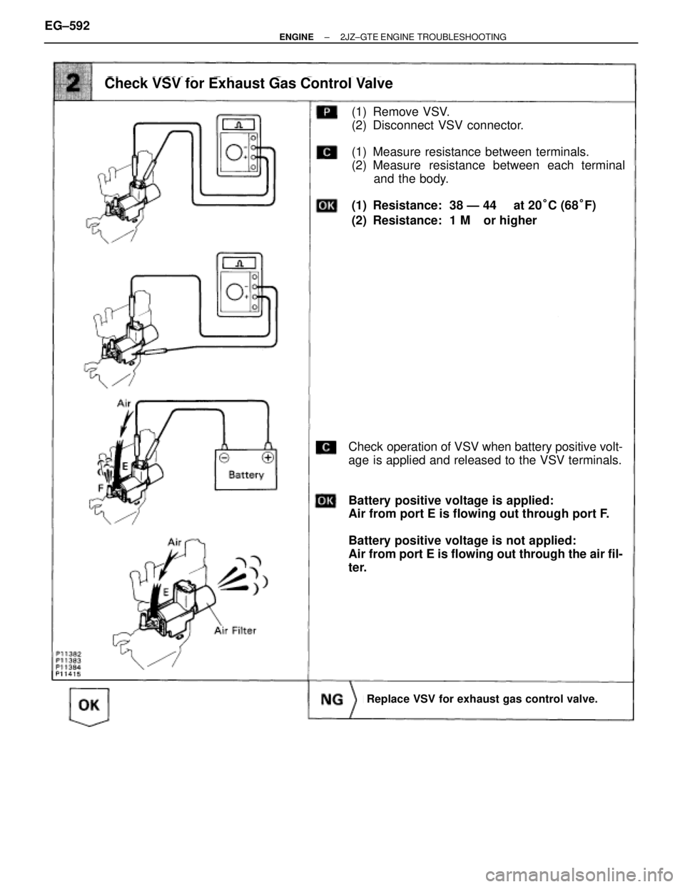
(1) Remove VSV.
(2) Disconnect VSV connector.
(1) Measure resistance between terminals.
(2) Measure resistance between each terminal
and the body.
(1) Resistance: 38 Ð 44 � at 20°C (68°F)
(2) Resistance: 1 M� or higher
Check operation of VSV when battery positive volt-
age is applied and released to the VSV terminals.
Battery positive voltage is applied:
Air from port E is flowing out through port F.
Battery positive voltage is not applied:
Air from port E is flowing out through the air fil-
ter.
Check VSV for Exhaust Gas Control Valve
Replace VSV for exhaust gas control valve.
EG±592± ENGINE2JZ±GTE ENGINE TROUBLESHOOTING
Page 2100 of 2543
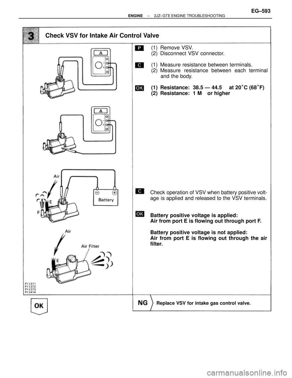
(1) Remove VSV.
(2) Disconnect VSV connector.
(1) Measure resistance between terminals.
(2) Measure resistance between each terminal
and the body.
(1) Resistance: 38.5 Ð 44.5 � at 20°C (68°F)
(2) Resistance: 1 M� or higher
Check operation of VSV when battery positive volt-
age is applied and released to the VSV terminals.
Battery positive voltage is applied:
Air from port E is flowing out through port F.
Battery positive voltage is not applied:
Air from port E is flowing out through the air
filter.
Check VSV for Intake Air Control Valve
Replace VSV for intake gas control valve.
± ENGINE2JZ±GTE ENGINE TROUBLESHOOTINGEG±593
Page 2103 of 2543
INSPECTION PROCEDURE
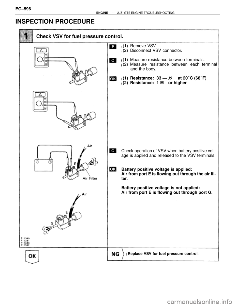
(1) Remove VSV.
(2) Disconnect VSV connector.
(1) Measure resistance between terminals.
(2) Measure resistance between each terminal
and the body.
(1) Resistance: 33 Ð ��� � at 20°C (68°F)
(2) Resistance: 1 M� or higher
Check operation of VSV when battery positive volt-
age is applied and released to the VSV terminals.
Battery positive voltage is applied:
Air from port E is flowing out through the air fil-
ter.
Battery positive voltage is not applied:
Air from port E is flowing out through port G.
Check VSV for fuel pressure control.
Replace VSV for fuel pressure control.
EG±596± ENGINE2JZ±GTE ENGINE TROUBLESHOOTING
Page 2135 of 2543
![TOYOTA SUPRA 1995 Service Repair Manual To Ignition SW
IG Terminal
Fuse
Relay
SW2 SolenoidVoltmeter [A]
[B]
[C] SW1
Ohmmeter
SW
INTRODUCTION±HOW TO PERFORM FOR SYSTEM INSPECTION
A±5
6
Wire Harness Repair Manual (RM1022E)
HOW TO PERFORM FO](/manual-img/14/57468/w960_57468-2134.png "TOYOTA SUPRA 1995 Service Repair Manual To Ignition SW
IG Terminal
Fuse
Relay
SW2 SolenoidVoltmeter [A]
[B]
[C] SW1
Ohmmeter
SW
INTRODUCTION±HOW TO PERFORM FOR SYSTEM INSPECTION
A±5
6
Wire Harness Repair Manual (RM1022E)
HOW TO PERFORM FO")
To Ignition SW
IG Terminal
Fuse
Relay
SW2 SolenoidVoltmeter [A]
[B]
[C] SW1
Ohmmeter
SW
INTRODUCTION±HOW TO PERFORM FOR SYSTEM INSPECTION
A±5
6
Wire Harness Repair Manual (RM1022E)
HOW TO PERFORM FOR SYSTEM INSPECTION
This inspection procedure is a simple troubleshooting which should be carried out on the vehicle during
system operation and is based on the assumption of system component trouble
Always inspect the trouble taking the following items into consideration:
�Ground point fault
�Open or short circuit of the wire harness
�Connector or terminal connection fault
�Fuse or fusible link fault
NOTICE:
�This is an on±vehicle inspection during system operation.
Therefore, inspect the trouble with due regard for safety.
�If connecting the battery directly, be careful not to cause a short circuit, and select the applicable
voltage.
1. Voltage Check
(a)Establish conditions in which voltage is present at the
check point.
Example:
[A] ± Ignition SW on
[B] ± Ignition SW and SW 1 on
[C] ± Ignition SW, SW 1 and Relay on (SW 2 off)
(b)Using a voltmeter, connect the negative (±) lead to a
good ground point or negative (±) battery terminal
and the positive (+) lead to the connector or
component terminal. This check can be done with a
test bulb instead of a voltmeter.
2. Continuity and Resistance Check
(a)Disconnect the battery terminal or wire so there is no
voltage between the check points.
(b)Contact the two leads of an ohmmeter to each of the
check points.
A
Page 2136 of 2543

If the circuit has diodes, reverse t")
Diode Ohmmeter
Diode Ohmmeter
Digital Type Analog Type
Bulb Ohmmeter
A±6
INTRODUCTION±HOW TO PERFORM FOR SYSTEM INSPECTION
7
Wire Harness Repair Manual (RM1022E)
If the circuit has diodes, reverse the two leads and check
again.
When touching the negative (±) lead to the diode positive
(+) side and the positive (+) lead to the negative (±) side,
there should be continuity. When touching the two leads in
reverse, there should be no continuity.
HINT: Specifications may vary depending on the type of
tester, so refer to the tester's instruction manual before
performing the inspection.
Check LED (Light Emitting Diode) in the same manner as
that for diodes.
HINT:
�Use a tester with a power source of 3V or greater to
overcome the circuit resistance.
�If a suitable tester is not available, apply battery
voltage and check that the LED lights up.
(c)Use a volt/ohmmeter with high impedance (10kW/V
minimum) for troubleshooting of the electrical circuit.
3. Bulb Check
(a)Remove the bulb.
(b)There should be continuity between the respective
terminals of the bulb together with a certain amount
of resistance.
(c)Apply the two leads of the ohmmeter to each of the
terminals.
(d)Apply battery voltage and check that the bulb light up.
A
.
(See page EG±514).
Disconnect IAC valve connector.
Measure resistance between terminals shown be-
low.
Check IAC valve.
Check for open and short in harness and")