Page 1330 of 2543
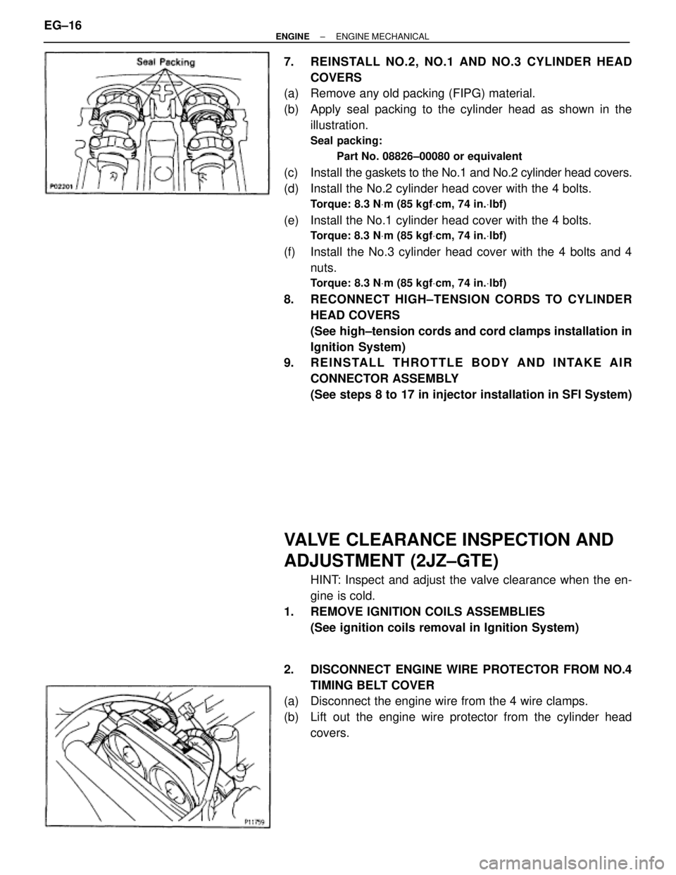
7. REINSTALL NO.2, NO.1 AND NO.3 CYLINDER HEAD
COVERS
(a) Remove any old packing (FIPG) material.
(b) Apply seal packing to the cylinder head as shown in the
illustration.
Seal packing:
Part No. 08826±00080 or equivalent
(c) Install the gaskets to the No.1 and No.2 cylinder head covers.
(d) Install the No.2 cylinder head cover with the 4 bolts.
Torque: 8.3 NVm (85 kgfVcm, 74 in.Vlbf)
(e) Install the No.1 cylinder head cover with the 4 bolts.
Torque: 8.3 NVm (85 kgfVcm, 74 in.Vlbf)
(f) Install the No.3 cylinder head cover with the 4 bolts and 4
nuts.
Torque: 8.3 NVm (85 kgfVcm, 74 in.Vlbf)
8. RECONNECT HIGH±TENSION CORDS TO CYLINDER
HEAD COVERS
(See high±tension cords and cord clamps installation in
Ignition System)
9. REINSTALL THROTTLE BODY AND INTAKE AIR
CONNECTOR ASSEMBLY
(See steps 8 to 17 in injector installation in SFI System)
VALVE CLEARANCE INSPECTION AND
ADJUSTMENT (2JZ±GTE)
HINT: Inspect and adjust the valve clearance when the en-
gine is cold.
1. REMOVE IGNITION COILS ASSEMBLIES
(See ignition coils removal in Ignition System)
2. DISCONNECT ENGINE WIRE PROTECTOR FROM NO.4
TIMING BELT COVER
(a) Disconnect the engine wire from the 4 wire clamps.
(b) Lift out the engine wire protector from the cylinder head
covers. EG±16
± ENGINEENGINE MECHANICAL
Page 1334 of 2543
IGNITION TIMING INSPECTION
(2JZ±GTE)
1. WARM UP ENGINE
Allow the engine to warm up to normal operating tempera-
ture.
2. CONNECT TACHOMETER AND TIMING LIGHT
(See step 2 in ignition timing inspection and adjustment
(2JZ±GE))
3. CHECK IDLE SPEED
(a) Race the engine speed at 2,500 rpm for approx. 90 seconds.
(b) Check the idle speed.
Idle speed:
650 + 50 rpm
4. CHECK IGNITION TIMING
(a) Using SST, connect terminals TE1 and E1 of the DLC 1.
SST 09843±18020
(b) Open the igniter connector cover and remove the green lead
wire.
(c) Connect the timing light clip to the green lead wire.
NOTICE:
wUse a timing light that can detect the primary signal.
wAfter finishing the inspection, make sure the lead wire is
stored inside the connector cover.
EG±20± ENGINEENGINE MECHANICAL
Page 1335 of 2543
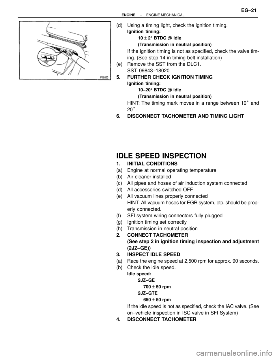
(d) Using a timing light, check the ignition timing.
Ignition timing:
10 + 25 BTDC @ idle
(Transmission in neutral position)
If the ignition timing is not as specified, check the valve tim-
ing. (See step 14 in timing belt installation)
(e) Remove the SST from the DLC1.
SST 09843±18020
5. FURTHER CHECK IGNITION TIMING
Ignition timing:
10±205 BTDC @ idle
(Transmission in neutral position)
HINT: The timing mark moves in a range between 10° and
20°.
6. DISCONNECT TACHOMETER AND TIMING LIGHT
IDLE SPEED INSPECTION
1. INITIAL CONDITIONS
(a) Engine at normal operating temperature
(b) Air cleaner installed
(c) All pipes and hoses of air induction system connected
(d) All accessories switched OFF
(e) All vacuum lines properly connected
HINT: All vacuum hoses for EGR system, etc. should be prop-
erly connected.
(f) SFI system wiring connectors fully plugged
(g) Ignition timing set correctly
(h) Transmission in neutral position
2. CONNECT TACHOMETER
(See step 2 in ignition timing inspection and adjustment
(2JZ±GE))
3. INSPECT IDLE SPEED
(a) Race the engine speed at 2,500 rpm for approx. 90 seconds.
(b) Check the idle speed.
Idle speed:
2JZ±GE
700 + 50 rpm
2JZ±GTE
650 + 50 rpm
If the idle speed is not as specified, check the IAC valve. (See
on±vehicle inspection in ISC valve in SFI System)
4. DISCONNECT TACHOMETER
± ENGINEENGINE MECHANICALEG±21
Page 1338 of 2543
TIMING BELT REMOVAL
1. REMOVE RADIATOR ASSEMBLY
(See radiator removal in Cooling System)
2. 2JZ±GTE M/T:
REMOVE DRIVE BELT TENSIONER DAMPER
Remove the 2 nuts and tensioner damper.
3. REMOVE DRIVE BELT, FAN, FLUID COUPLING
ASSEMBLY AND WATER PUMP PULLEY
(See step 6 in water pump removal in Cooling System)
4. REMOVE NO.3 TIMING BELT COVER
(a) Remove the oil filler cap.
(b) 2JZ±GE:
Using a 5 mm hexagon wrench, remove the 6 bolts and belt
cover.
(c) 2JZ±GTE:
Using a 5 mm hexagon wrench, remove the 10 bolts and belt
cover.
5. REMOVE NO.2 TIMING BELT COVER
Using a 5 mm hexagon wrench, remove the 3 bolts, belt cover
and gasket.
If you are unable to loosen the bolt on the right because the
PS pump pulley interferes with the hexagon wrench, first re-
move the pulley.
6. REMOVE DRIVE BELT TENSIONER
Remove the 3 bolts and tensioner. EG±24
± ENGINEENGINE MECHANICAL
Page 1341 of 2543
13. REMOVE NO.1 TIMING BELT COVER
Remove the 5 bolts, timing belt cover and gasket.
14. REMOVE TIMING BELT GUIDE
15. REMOVE TIMING BELT
HINT (When re±using timing belt): Draw an arrow on the tim-
ing belt in the direction of engine revolution, and place match-
marks on the timing belt and crankshaft timing pulley.
16. REMOVE IDLER PULLEY
Using a 10 mm hexagon wrench, remove the pivot bolt, plate
washer and idler pulley.
17. REMOVE CRANKSHAFT TIMING PULLEY
(a) 2JZ±GTE:
Remove the bolt and timing belt plate.
(b) Remove the crankshaft timing pulley.
If the pulley cannot be removed by hand, use SST to remove
the crankshaft timing pulley.
SST 09950±50010 (09951±05010, 09952±05010,
09953±05020, 09954±00010)
± ENGINEENGINE MECHANICALEG±27
Page 1343 of 2543
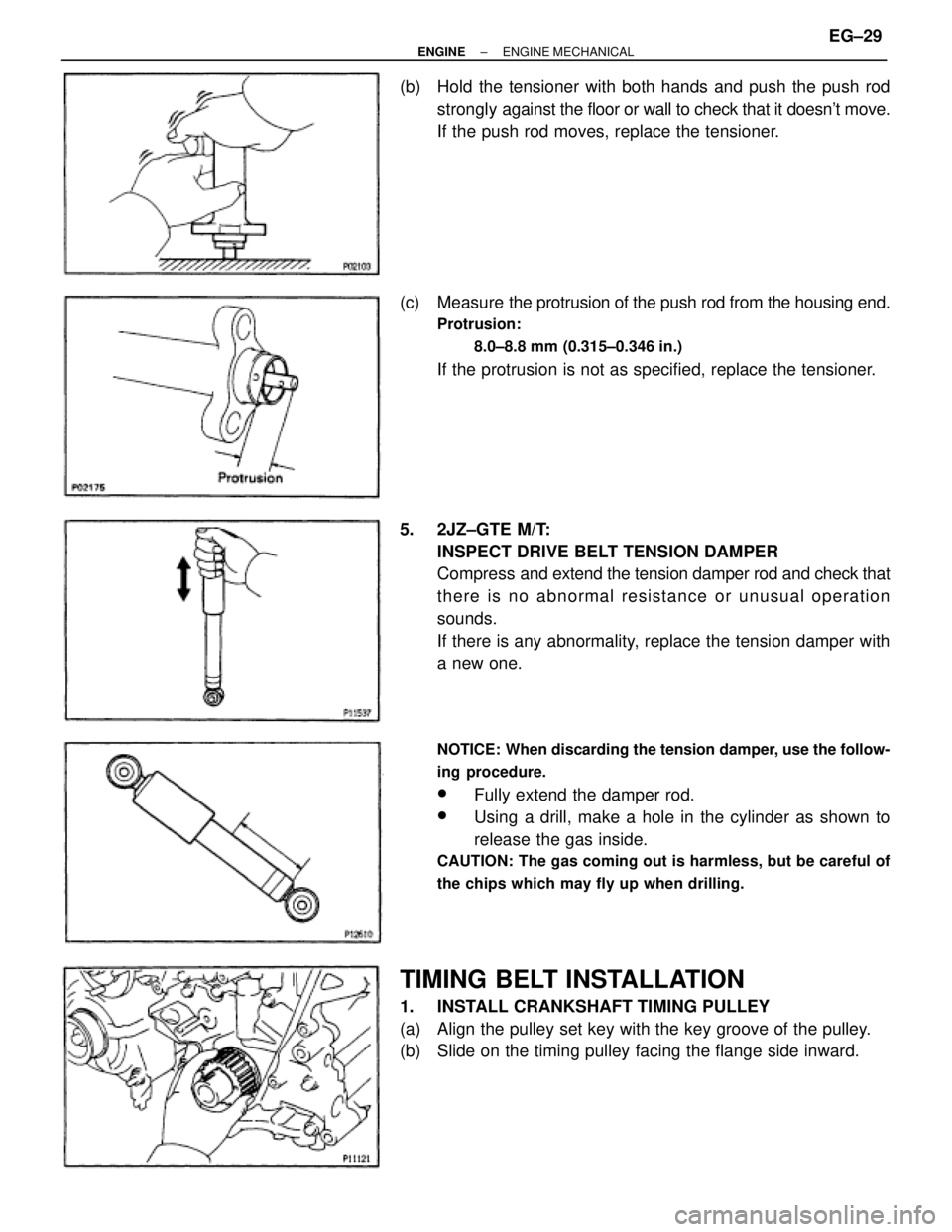
(b) Hold the tensioner with both hands and push the push rod
strongly against the floor or wall to check that it doesn't move.
If the push rod moves, replace the tensioner.
(c) Measure the protrusion of the push rod from the housing end.
Protrusion:
8.0±8.8 mm (0.315±0.346 in.)
If the protrusion is not as specified, replace the tensioner.
5. 2JZ±GTE M/T:
INSPECT DRIVE BELT TENSION DAMPER
Compress and extend the tension damper rod and check that
there is no abnormal resistance or unusual operation
sounds.
If there is any abnormality, replace the tension damper with
a new one.
NOTICE: When discarding the tension damper, use the follow-
ing procedure.
wFully extend the damper rod.
wUsing a drill, make a hole in the cylinder as shown to
release the gas inside.
CAUTION: The gas coming out is harmless, but be careful of
the chips which may fly up when drilling.
TIMING BELT INSTALLATION
1. INSTALL CRANKSHAFT TIMING PULLEY
(a) Align the pulley set key with the key groove of the pulley.
(b) Slide on the timing pulley facing the flange side inward.
± ENGINEENGINE MECHANICALEG±29
Page 1344 of 2543
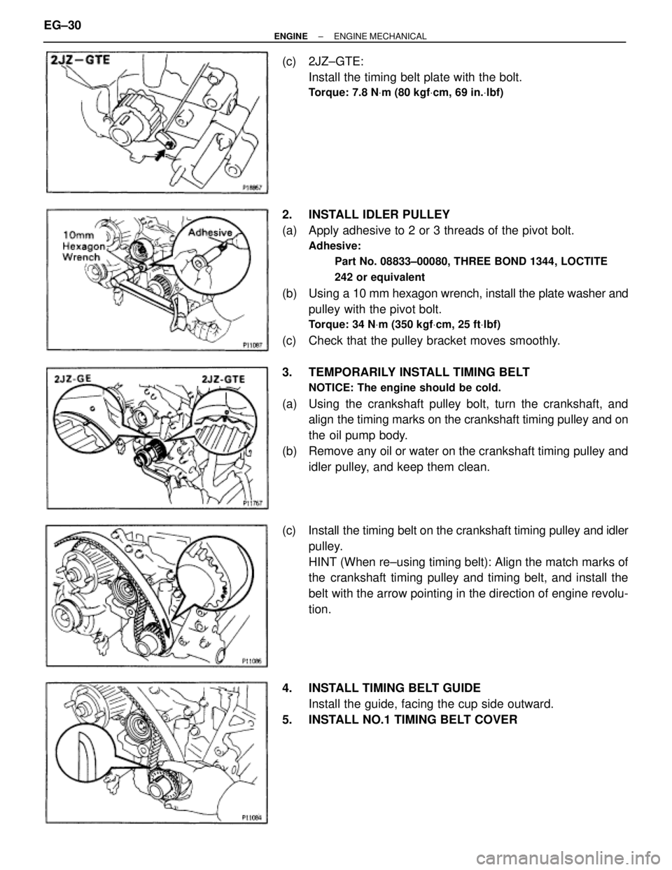
(c) 2JZ±GTE:
Install the timing belt plate with the bolt.
Torque: 7.8 NVm (80 kgfVcm, 69 in.Vlbf)
2. INSTALL IDLER PULLEY
(a) Apply adhesive to 2 or 3 threads of the pivot bolt.
Adhesive:
Part No. 08833±00080, THREE BOND 1344, LOCTITE
242 or equivalent
(b) Using a 10 mm hexagon wrench, install the plate washer and
pulley with the pivot bolt.
Torque: 34 NVm (350 kgfVcm, 25 ftVlbf)
(c) Check that the pulley bracket moves smoothly.
3. TEMPORARILY INSTALL TIMING BELT
NOTICE: The engine should be cold.
(a) Using the crankshaft pulley bolt, turn the crankshaft, and
align the timing marks on the crankshaft timing pulley and on
the oil pump body.
(b) Remove any oil or water on the crankshaft timing pulley and
idler pulley, and keep them clean.
(c) Install the timing belt on the crankshaft timing pulley and idler
pulley.
HINT (When re±using timing belt): Align the match marks of
the crankshaft timing pulley and timing belt, and install the
belt with the arrow pointing in the direction of engine revolu-
tion.
4. INSTALL TIMING BELT GUIDE
Install the guide, facing the cup side outward.
5. INSTALL NO.1 TIMING BELT COVER EG±30
± ENGINEENGINE MECHANICAL
Page 1347 of 2543
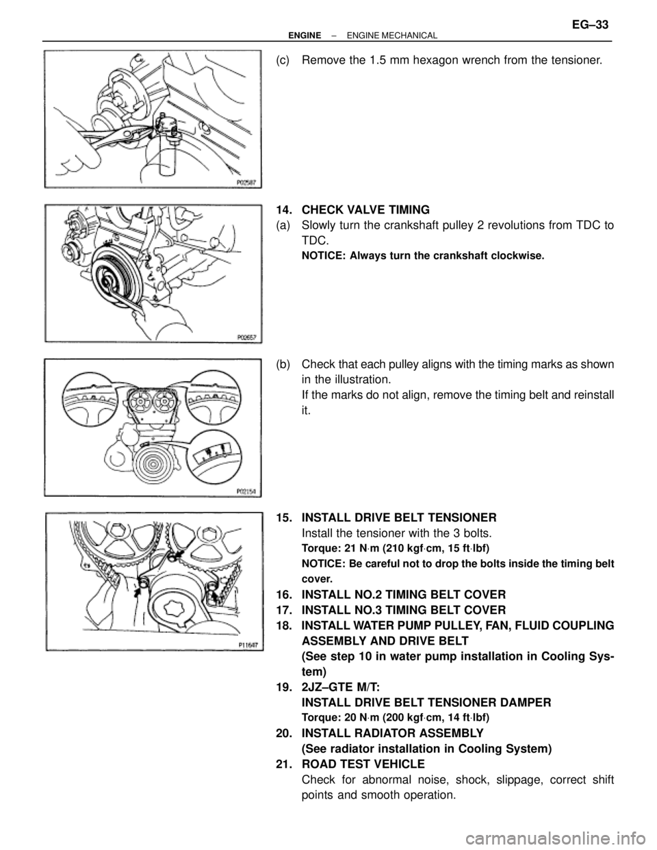
(c) Remove the 1.5 mm hexagon wrench from the tensioner.
14. CHECK VALVE TIMING
(a) Slowly turn the crankshaft pulley 2 revolutions from TDC to
TDC.
NOTICE: Always turn the crankshaft clockwise.
(b) Check that each pulley aligns with the timing marks as shown
in the illustration.
If the marks do not align, remove the timing belt and reinstall
it.
15. INSTALL DRIVE BELT TENSIONER
Install the tensioner with the 3 bolts.
Torque: 21 NVm (210 kgfVcm, 15 ftVlbf)
NOTICE: Be careful not to drop the bolts inside the timing belt
cover.
16. INSTALL NO.2 TIMING BELT COVER
17. INSTALL NO.3 TIMING BELT COVER
18. INSTALL WATER PUMP PULLEY, FAN, FLUID COUPLING
ASSEMBLY AND DRIVE BELT
(See step 10 in water pump installation in Cooling Sys-
tem)
19. 2JZ±GTE M/T:
INSTALL DRIVE BELT TENSIONER DAMPER
Torque: 20 NVm (200 kgfVcm, 14 ftVlbf)
20. INSTALL RADIATOR ASSEMBLY
(See radiator installation in Cooling System)
21. ROAD TEST VEHICLE
Check for abnormal noise, shock, slippage, correct shift
points and smooth operation.
± ENGINEENGINE MECHANICALEG±33