Page 852 of 2248
1. Supplemental Restraint System
“Airbag”
Airbag system wiring harness is routed near the instrument
panel, heater unit, blower motor and control unit.
CAUTION:
�All Airbag system wiring harness and connectors
are colored yellow. Do not use electrical test equip-
ment on these circuit.
�Be careful not to damage Airbag system wiring har-
ness when servicing the instrument panel, heater unit,
blower motor and control unit.
2. Heater Unit
A: REMOVAL AND INSTALLATION
1) Disconnect GND cable from battery.
2) Remove heater hoses (inlet, outlet) in engine compart-
ment.
NOTE:
Drain as much coolant from heater unit as possible, and
plug disconnected hose with cloth.
3) Remove instrument panel.
4) Remove steering support beam.
5) Remove evaporator. (With A/C model)
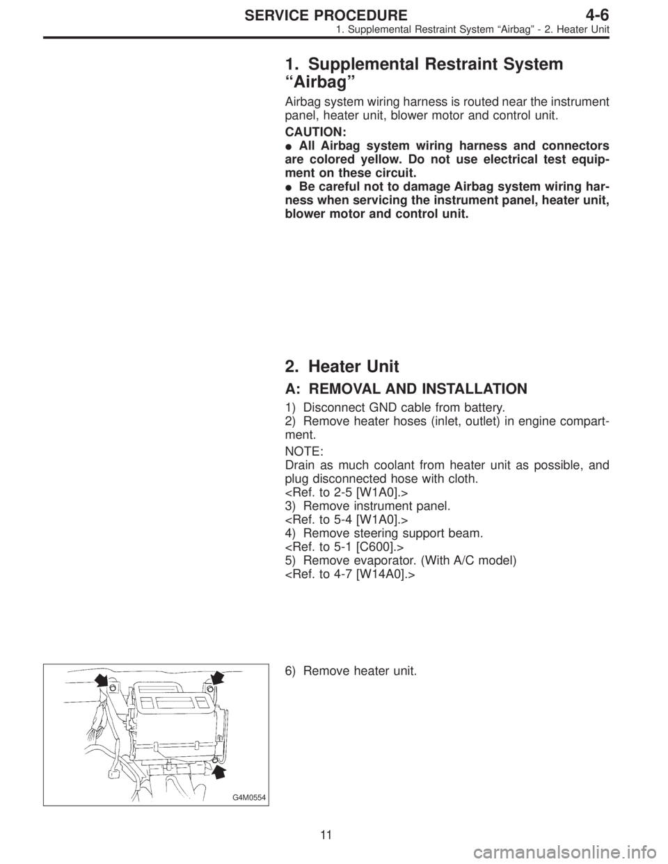
G4M0554
6) Remove heater unit.
11
4-6SERVICE PROCEDURE
1. Supplemental Restraint System“Airbag”- 2. Heater Unit
Page 860 of 2248
B4M0063
6. Mode Door Motor
A: REMOVAL
1) Remove instrument panel.
2) Remove mode door motor.
B4M0064A
B: INSPECTION
1) When approx. 12 V is applied to the mode door motor
terminals, mode door motor operates as follows:
LHD model
Terminal No.
Mode door motor
21
Polarity of power supply
terminalsMode door motor
operationDirection of linkage
rotation
� + VENT,DEF Clockwise
+� DEF,VENT Counterclockwise
RHD model
Terminal No.
Mode door motor
76
Polarity of power supply
terminalsMode door motor
operationDirection of linkage
rotation
� + VENT,DEF Clockwise
+� DEF,VENT Counterclockwise
2) Check mode door motor position switch.
When the mode door motor is moved to each mode posi-
tion by using the mode selector switch, check if continuity
exists between each terminal as follows:
LHD model
Mode selector switch
positionsTerminal No.
VENT 8 or 7
9 (GND) BI-LEV 6 or 7
HEAT 5or6
DEF/HEAT 4 or 5
DEF 3or4
18
4-6SERVICE PROCEDURE
6. Mode Door Motor
Page 885 of 2248
 Begin at the connection of the low-pressure tube to the
evaporator, and work your way along the low-pressure of
the system to the compressor. There are thre")
G4M0615
5. LEAK TEST—LOW-PRESSURE SIDE
1) Begin at the connection of the low-pressure tube to the
evaporator, and work your way along the low-pressure of
the system to the compressor. There are three places to
check on each tube connection.
2) Check the area.
(1) Check the area where the fitting joins the tube.
(2) Check the area where the two parts of the fitting
join each other.
G4M0616
(3) Check the area where the nut joins the tube.
G4M0617
6. CHECK THE FLEXIBLE HOSES
Visually inspect the rubber portions of the flexible hoses for
cracking. Probe the rubber section, including the ends of
any insulators or protectors which may cover sections of
the rubber hose, and near the ends where the rubber
meets the metal collar.
NOTE:
Be certain to move the probe slowly [approximately 25 mm
(1 in) per second] when probing along any length of hose
or tube.
G4M0618
7. CHECK THE EVAPORATOR ASSEMBLY
1) Use one or both of the following methods to check the
evaporator assembly.
2) Remove the drain hose from the case drain nipple. Hold
the probe at the end of the case drain nipple for at least 10
seconds. Be certain to reconnect the drain hose when fin-
ished.
3) With the ignition key in the“ACC”position, run the
blower on high speed for 1 minute, then turn the blower off.
Place the probe in the center instrument panel vent, an turn
the blower on low speed for 1 to 2 seconds, then turn the
blower off. Leave the probe in the vent for at least 10 sec-
onds.
25
4-7SERVICE PROCEDURE
8. Leak Testing
Page 1008 of 2248
 Positioning glass
(1) Mount glass on body.
(2) Adjust position of glass so that gap between body
and glass is uniform on all sides.
(3) Put matching pin on body and glass in several
places.")
G5M0407
4) Positioning glass
(1) Mount glass on body.
(2) Adjust position of glass so that gap between body
and glass is uniform on all sides.
(3) Put matching pin on body and glass in several
places.
B5M0088A
5) Cleaning glass
(1) Dismount glass from body.
(2) Clean surface of glass to be adhered with alcohol
or white gasoline.
6) Stick dam rubber and install front molding upper.
While aligning ceramic print notch�
1on windshield upper
portion with mark�
2in center of upper front molding, install
upper front molding on windshield.
G5M0495
7) Application of primer
(1) Using a sponge, apply primer to part of glass to be
adhered.
(2) Apply primer to part of body to be adhered.
CAUTION:
�Primer is hard to wipe off of body paint, instrument
panel, inner trim, etc. So put masking around these
areas for protection.
�After application, let 1st primer dry spontaneously
for about 10 minutes.
�Do not touch primer-coated surface under any cir-
cumstances.
G5M0408
8) Application of adhesive
(1) Cut nozzle tip of cartridge as shown in figure.
(2) Open cartridge and put it into a gun with nozzle
attached.
(3) Apply adhesive uniformly to all sides of adhesion
surface while operating gun along glass end face.
33
5-2SERVICE PROCEDURE
5. Windshield
Page 1036 of 2248
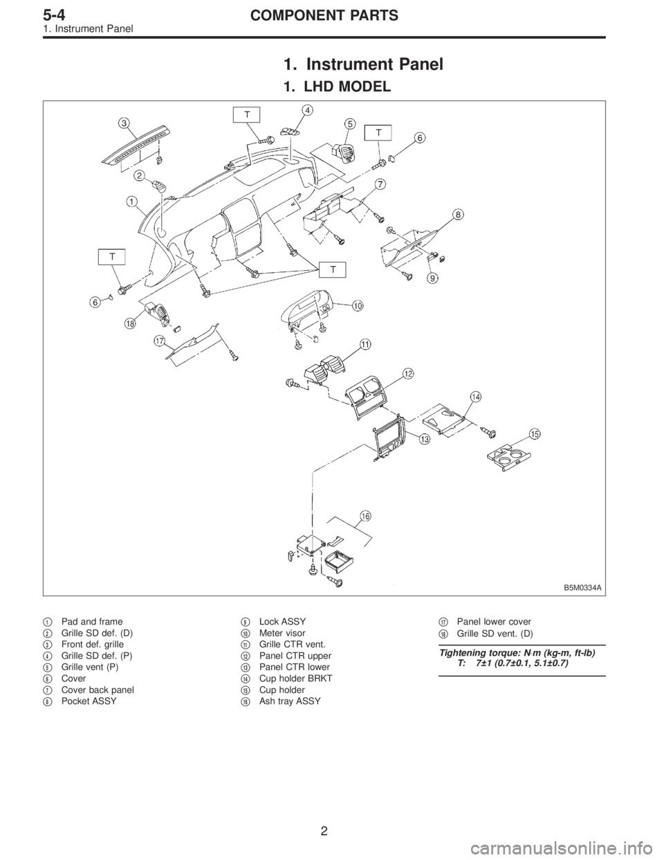
1. Instrument Panel
1. LHD MODEL
B5M0334A
�1Pad and frame
�
2Grille SD def. (D)
�
3Front def. grille
�
4Grille SD def. (P)
�
5Grille vent (P)
�
6Cover
�
7Cover back panel
�
8Pocket ASSY�
9Lock ASSY
�
10Meter visor
�
11Grille CTR vent.
�
12Panel CTR upper
�
13Panel CTR lower
�
14Cup holder BRKT
�
15Cup holder
�
16Ash tray ASSY�
17Panel lower cover
�
18Grille SD vent. (D)
Tightening torque: N⋅m (kg-m, ft-lb)
T: 7±1 (0.7±0.1, 5.1±0.7)
2
5-4COMPONENT PARTS
1. Instrument Panel
Page 1037 of 2248
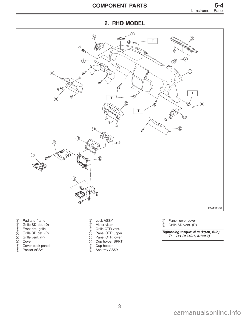
2. RHD MODEL
B5M0388A
�1Pad and frame
�
2Grille SD def. (D)
�
3Front def. grille
�
4Grille SD def. (P)
�
5Grille vent. (P)
�
6Cover
�
7Cover back panel
�
8Pocket ASSY�
9Lock ASSY
�
10Meter visor
�
11Grille CTR vent.
�
12Panel CTR upper
�
13Panel CTR lower
�
14Cup holder BRKT
�
15Cup holder
�
16Ash tray ASSY�
17Panel lower cover
�
18Grille SD vent. (D)
Tightening torque: N⋅m (kg-m, ft-lb)
T: 7±1 (0.7±0.1, 5.1±0.7)
3
5-4COMPONENT PARTS
1. Instrument Panel
Page 1039 of 2248
1. Instrument Panel
Airbag system wiring harness is routed near combination
meter.
CAUTION:
�All Airbag system wiring harness and connectors
are colored yellow. Do not use electrical test equip-
ment on these circuits.
�Be careful not to damage Airbag system wiring har-
ness when servicing the combination meter.
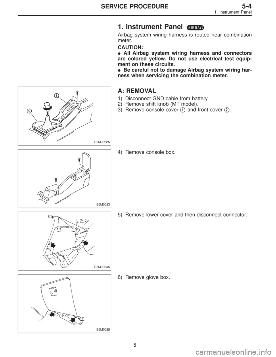
B5M0022A
A: REMOVAL
1) Disconnect GND cable from battery.
2) Remove shift knob (MT model).
3) Remove console cover�
1and front cover�2.
B5M0023
4) Remove console box.
B5M0024A
5) Remove lower cover and then disconnect connector.
B5M0025
6) Remove glove box.
5
5-4SERVICE PROCEDURE
1. Instrument Panel
Page 1040 of 2248
B5M0026
7) Remove cover back panel.
G5M0278
8) Remove two bolts and lower steering column.
B5M0027
9) Set temperature control lever to Max. COLD position,
and then disconnect temperature control cable from link of
heater module.
NOTE:
Do not move lever and link when installing.
B5M0028
10) Remove bolt cover and bolt of both side.
B5M0029A
11) Remove front side sill cover RH and then disconnect
airbag connector (AB9) and (AB10) (Airbag model).
to 5-5 [M2-6].>
6
5-4SERVICE PROCEDURE
1. Instrument Panel
![SUBARU LEGACY 1995 Service Repair Manual B4M0063
6. Mode Door Motor
A: REMOVAL
1) Remove instrument panel. <Ref. to 5-4 [W1A0].>
2) Remove mode door motor.
B4M0064A
B: INSPECTION
1) When approx. 12 V is applied to the mode door motor
termina](/manual-img/17/57432/w960_57432-859.png "SUBARU LEGACY 1995 Service Repair Manual B4M0063
6. Mode Door Motor
A: REMOVAL
1) Remove instrument panel. <Ref. to 5-4 [W1A0].>
2) Remove mode door motor.
B4M0064A
B: INSPECTION
1) When approx. 12 V is applied to the mode door motor
termina")
 Remove cover back panel.
G5M0278
8) Remove two bolts and lower steering column.
B5M0027
9) Set temperature control lever to Max. COLD position,
and then disconnect temperature control cable")