Page 1501 of 1701
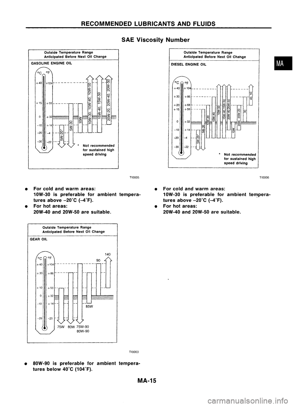
RECOMMENDEDLUBRICANTSANDFLUIDS
Outside Temperature Range
Anticipated BeforeNextOilChange
GASOLINE ENGINEOIL
SAE
Viscosity Number
OutsideTemperature Range
Anticipated BeforeNextOilChahge
DIESEL ENGINE OIL
•
°C of
+40 +10
---------
------~
+30 +86
-------
------0
0
o
...
'"
'"
+20 +68
0
~
~
---
-
-
'!2
0
+15 +59
'"
'"
0
~
0
0
'i'
0
~
'i
't
'"
?: ~
;:
0
~
0
'7 '"
N
-
'"
0 +32
~ ~
0
-10 +14
-t
;:
~
-20
-4
-'i'
~
-30 -22
•Not recommended
for sustained high
speed driving
lI)
~
0 0
~
'"
0
0
~'
'i
~~
~
0
(\J
0
-30
*
Not recommended
for sustained high
speed driving
-20
+32
-10 +14
+15
+59-----
TI0005
TIOOG6
• For cold andwarm areas:
10W-30 ispreferable forambient tempera-
tures above -20°C(-4°F).
• For hotareas:
20W-40 and20W-50 aresuitable. •
For cold andwarm areas:
10W-30 ispreferable forambient te~pera-
tures above -20°C(-4°F).
• For hotareas:
20W.40 and20W-50 aresuitable.
Outside Temperature Range
Anticipated BeforeNext011Change
GEAR OIL
140
°C
of
90
+40 +104
-------
+30 +86
+10 +50
-
0
%
-10
-29 -20
75W BOW75W-90
BOW-90
TI0003
• SOW-90 ispreferable forambient tempera-
tures below 40°C(104°F).
MA-15
Page 1510 of 1701
ENGINEMAINTENANCE
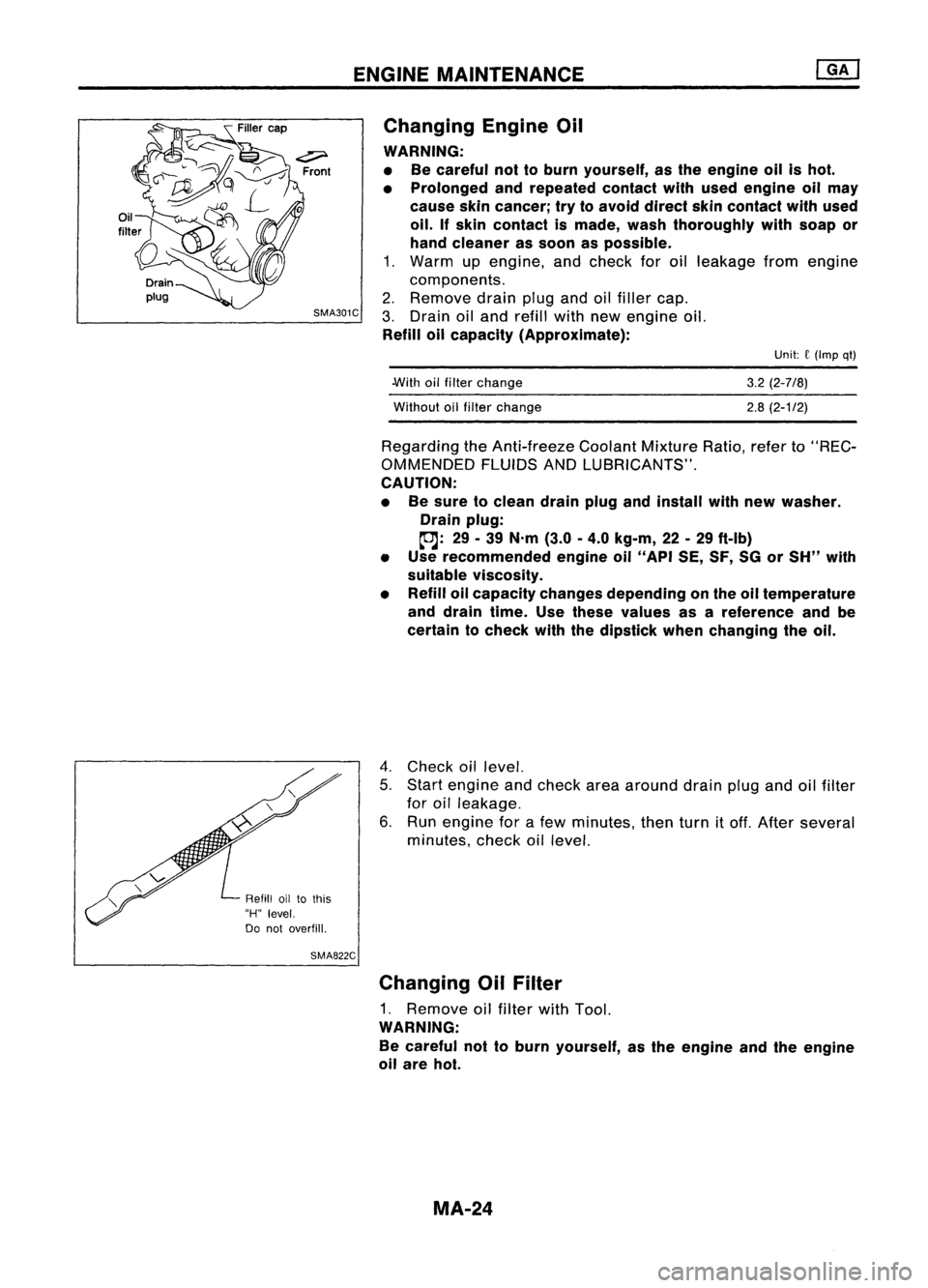
Changing EngineOil
WARNING:
• Becareful nottoburn yourself, asthe engine oilishot.
• Prolonged andrepeated contactwithused engine oilmay
cause skincancer; trytoavoid direct skincontact withused
oil.
If
skin contact ismade, washthoroughly withsoap or
hand cleaner assoon aspossible.
1. Warm upengine, andcheck foroilleakage fromengine
components.
2. Remove drainplugandoilfiller cap.
3. Drain oiland refill withnewengine oil.
Refill oilcapacity (Approximate):
Unit:
f
(Imp qt)
.With oilfilter change
Without oilfilter change
3.2
(2-7/8)
2.8 (2-1/2)
Regarding theAnti-freeze CoolantMixtureRatio,referto"REC-
OMMENDED FLUIDSANDLUBRICANTS".
CAUTION:
• Besure toclean drainplugandinstall withnew washer.
Drain plug:
~: 29-39 N'm (3.0-4.0 kg-m, 22-29 ft-Ib)
• Use recommended engineoil"API SE,SF,SGorSH" with
suitable viscosity.
• Refill oilcapacity changesdepending onthe oiltemperature
and drain time.Usethese values asareference andbe
certain tocheck withthedipstick whenchanging theoil.
4. Check oillevel.
5. Start engine andcheck areaaround drainplugandoilfilter
for oilleakage.
6. Run engine forafew minutes, thenturnitoff. After several
minutes, checkoillevel.
Refill oiltothis
"H" level.
Do not overfill.
SMA822C
Changing OilFilter
1. Remove oilfilter withTool.
WARNING:
Be careful nottoburn yourself, asthe engine andtheengine
oil are hot.
MA-24
Page 1519 of 1701
ENGINEMAINTENANCE ~
Changing FuelFilter (Cont'd)
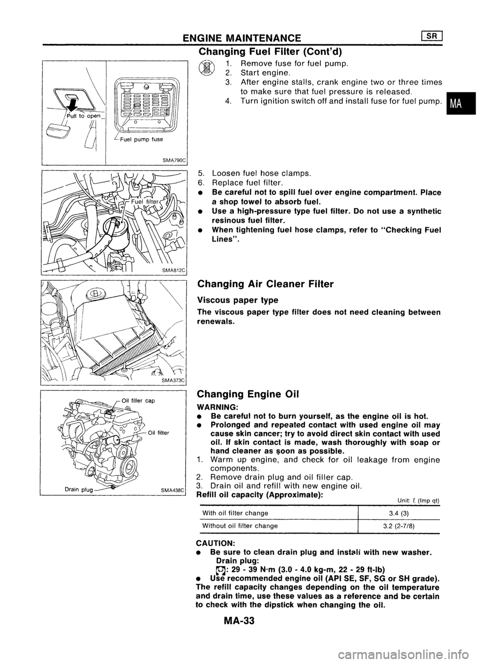
~ 1.Remove fuseforfuel pump.
~ 2.Start engine.
3. After engine stalls,crankengine twoorthree times
to make surethatfuel pressure isreleased. •
4. Turn ignition switchoffand install fuseforfuel pump.
i
Unit: C(Imp qt)
SMA790C
5.Loosen fuelhose clamps.
6. Replace fuelfilter.
• Becareful nottospill fuelover engine compartment. Place
a shop towel toabsorb fuel.
• Use ahigh-pressure typefuelfilter. Donot use asynthetic
resinous fuelfilter.
• When tightening fuelhose clamps, referto"Checking Fuel
Lines" .
Changing AirCleaner Filter
Viscous papertype
The viscous papertypefilter does notneed cleaning between
renewals.
Changing EngineOil
WARNING:
• Becareful nottoburn yourself, asthe engine oilishot.
• Prolonged andrepeated contactwithused engine oilmay
cause skincancer; trytoavoid direct skincontact withused
oil. Ifskin contact ismade, washthoroughly withsoap or
hand cleaner as$oon aspossible.
1. Warm upengine, andcheck foroilleakage fromengine
components.
2. Remove drainplugandoilfiller cap.
3. Drain oiland refill withnewengine oil.
Refill oilcapacity (Approximate):
With oilfilter change
Without oilfilter change
3.4
(3)
3.2 (2-7/8)
CAUTION: • Besure toclean drainplugandinstClili withnewwasher.
Drain plug:
~: 29-39 N'm (3.0
0
4.0 kg-m, 22-29 ftolb)
• Use recommended engineoil(API SE,SF,SGorSH grade).
The refill capacity changes depending onthe oiltemperature
and drain time,usethese values asareference andbecertain
to check withthedipstick whenchanging theoil.
MA-33
Page 1530 of 1701
ENGINEMAINTENANCE
Checking InjectionNozzle(Cont'd)
Nozzle side
Combustion
chamber side
SEF668A Checking IdleSpeed
PREPARATION
1: Make surethatinjection timingiscorrect.
2. Make surethatinjection nozzlesareingood condition.
3. Make surethatthefollowing partsareingood condition.
• Air cleaner clogging
• Glow system
• Engine oiland coolant levels
• Air intake system (Oilfiller cap,oillevel gauge, etc.)
4. Set shift lever in"Neutral" position.Engageparkingbrake
and lock both front andrear wheels withwheel chocks.
5. Turn offair conditioner, lightsandaccessories.
6. Warm upengine tonormal operating temperature.
7. Attach adiesel tachotester.
8. Race engine twoorthree times andcheck idlespeed.
Idle speed (M/T):
700~go rprn
9.
If
itis out ofspecification, adjustidlespeed withidlespeed
adjusting screw.
Securely locktheadjusting screwwithlock nut.
Idle speed
adjusting screw
Fuel injection pump
SMA420C
Replacing TimingBelt
Refer to"TIMING BELT"inEM section.
MA-44
Page 1532 of 1701
CHASSISANDBODY MAINTENANCE
Changing
MIT
Oil
1. Drain oilfrom drain plugandrefill withnewgear oil.
2. Check oillevel. (Refer to"Checking
M/T
Oil".)
Oil grade:
API GL-4
Viscosity: See "RECOMMENDED FLUIDSANDLUBRICANTS",
MA-14.
Capacity: RS5F30A 2.8-3.0f
(4-7/8 -5-114
Imppi)
RS5F31A 2.9-3.2£
(5-1/8 -5-518
Imppt)
RS5F32A 3.7-3.9£ (6-112 -
6-7/8
Imppt)
Drain plug:
(OJ:
15-20 N'm (1.5-2.0 kg-m, 11-14 ft-Ib)
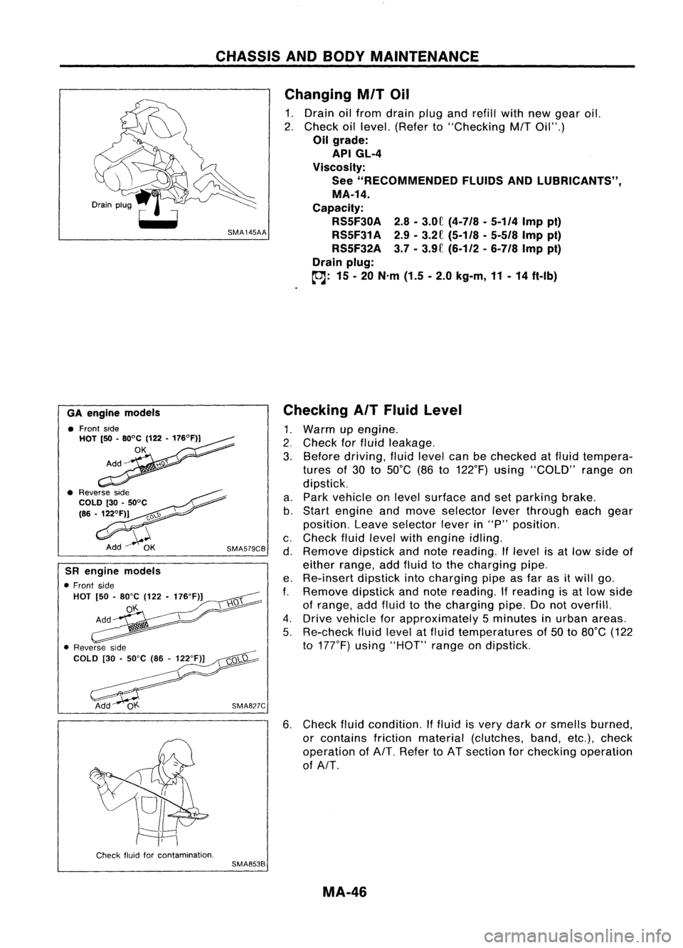
6. Check fluidcondition. Iffluid isvery dark orsmells burned,
or contains frictionmaterial (clutches, band,etc.),check
operation ofAlT. Refer toAT section forchecking operation
of AlT.
Checking
AIT
Fluid Level
1. Warm upengine .
2. Check forfluid leakage.
3. Before driving, fluidlevel canbechecked atfluid tempera-
tures of30 to50°C (86to122°F) using"COLD" rangeon
dipstick.
a. Park vehicle onlevel surface andsetparking brake.
b. Start engine andmove selector leverthrough eachgear
position. Leaveselector leverin"P" position.
c. Check fluidlevel withengine idling.
d. Remove dipstickandnote reading. Iflevel isat low side of
either range, addfluid tothe charging pipe.
e. Re-insert dipstickintocharging pipeasfar asitwill go.
f.
Remove dipstickandnote reading.
If
reading isat low side
of range, addfluid tothe charging pipe.Donot overfill.
4. Drive vehicle forapproximately 5minutes inurban areas.
5. Re-check fluidlevel atfluid temperatures of50 to80°C (122
to 177°F) using"HOT" rangeondipstick.
SMA827C
SMA579CB
GA
engine models
• Front side
HOT [50•80°C (122•176°F))
OK
SR engine models
• Front side
HOT [50•80"C (122-176"F)]
o'f..
Check fluidforcontamination.
SMA853B
MA-46
Page 1635 of 1701
SUPPLEMENTALRESTRAINTSYSTEM(SRS)
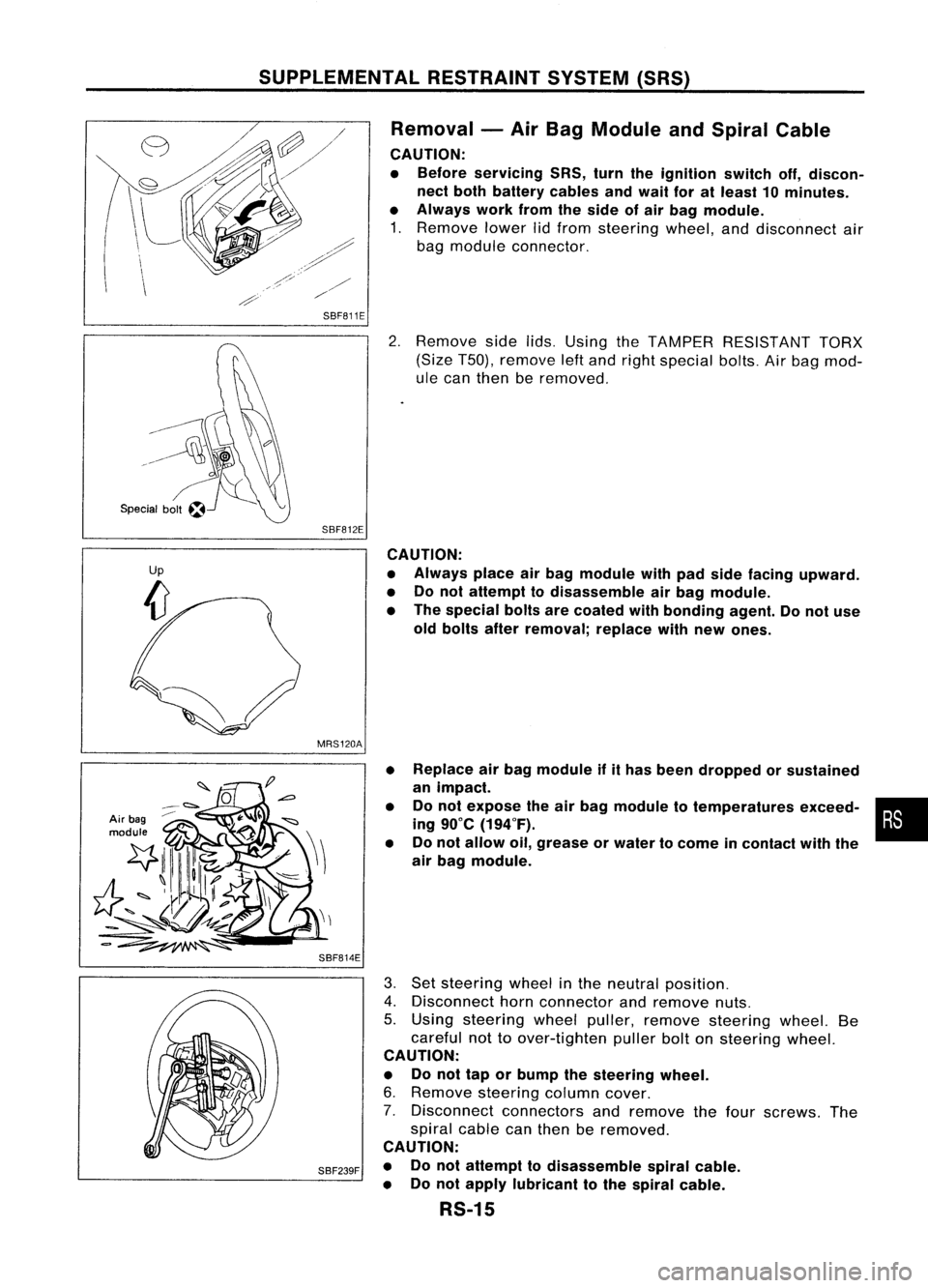
Removal -Air Bag Module andSpiral Cable
CAUTION:
• Before servicing SRS,turntheignition switchoff,discon-
nect both battery cablesandwait foratleast 10minutes.
• Always workfromtheside ofair bag module.
1. Remove lowerlidfrom steering wheel,anddisconnect air
bag module connector.
SBF811E
2.Remove sidelids.Using theTAMPER RESISTANT TORX
(Size T50), remove leftand right special bolts.Airbag mod-
ule can then beremoved.
SBF812E CAUTION:
• Always placeairbag module withpadside facing upward.
• Donot attempt todisassemble airbag module.
• The special boltsarecoated withbonding agent.Donot use
old bolts afterremoval; replacewithnew ones.
MRS120A
Air bag
module
SBF814E•
•
• Replace
airbag module ifithas been dropped orsustained
an impact.
Do not expose theairbag module totemperatures exceed-•
•
ing 90°C (194°F).
Do not allow oil,grease orwater tocome incontact withthe
air bag module.
SBF239F
3.
Set steering wheelinthe neutral position.
4. Disconnect hornconnector andremove nuts.
5. Using steering wheelpuller, remove steering wheel.Be
careful nottoover-tighten pullerboltonsteering wheel.
CAUTION:
• Donot tap orbump thesteering wheel.
6. Remove steering columncover.
7. Disconnect connectorsandremove thefour screws. The
spiral cablecanthen beremoved.
CAUTION:
• Donot attempt todisassemble spiralcable.
• Donot apply lubricant tothe spiral cable.
RS-15
Page 1636 of 1701
SUPPLEMENTALRESTRAINTSYSTEM(SRS)
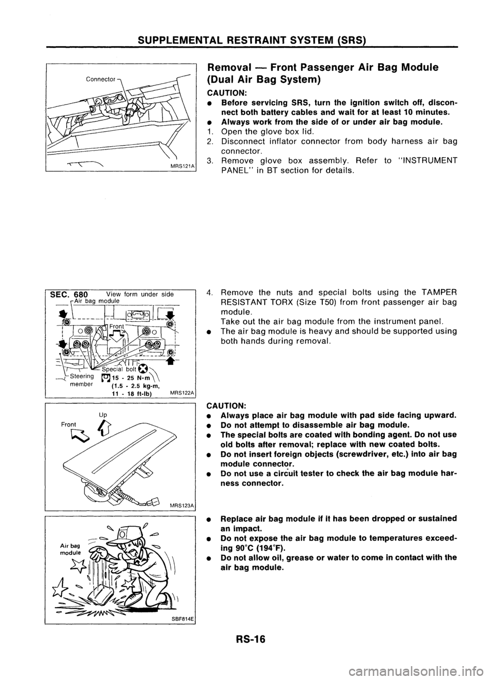
Removal -Front Passenger AirBag Module
(Dual AirBag System)
CAUTION:
• Before servicing SRS,turntheignition switchoff,discon-
nect both battery cablesandwait foratleast 10minutes.
• Always workfromtheside ofor under airbag module.
1. Open theglove boxlid.
2. Disconnect inflatorconnector frombody harness airbag
connector.
3. Remove gloveboxassembly. Referto"INSTRUMENT
PANEL" inBT section fordetails.
Air bag
module
4.
Remove thenuts andspecial boltsusing theTAMPER
RESISTANT TORX(SizeT50jfrom front passenger airbag
module.
Take outtheairbag module fromtheinstrument panel.
• The airbag module isheavy andshould besupported using
both hands during removal.
MRS122A
CAUTION:
• Always placeairbag module withpadside facing upward.
• Donot attempt todisassemble airbag module.
• The special boltsarecoated withbonding agent.Donot use
old bolts afterremoval; replacewithnewcoated bolts.
• Donot insert foreign objects (screwdriver, etc.)intoairbag
module connector.
• Donot use acircuit testertocheck theairbag module har-
ness connector.
• Replace airbag module ifithas been dropped orsustained
an impact.
• Donot expose theairbag module totemperatures exceed-
ing 90°C (194°F).
• Donot allow oil,grease orwater tocome incontact withthe
air bag module.
SBF814E RS-16
Page 1672 of 1701
ON-VEHICLESERVICE
Checking andAdjusting DriveBelts(Forpower
steering)
Refer to"Checking DriveBelts" for"ENGINE MAINTENANCE"
in MA section.
SST476C
S
r
SST681B Checking
Fluidlevel
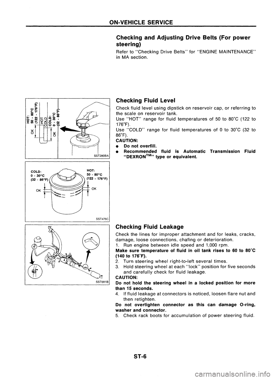
Check fluidlevel using dipstick onreservoir cap,orreferring to
the scale onreservoir tank.
Use "HOT" rangeforfluid temperatures of50 to80°C (122to
176°F).
Use "COLD" rangeforfluid temperatures of0to 30°C (32to
86°F).
CAUTION:
• Donot overfill.
• Recommended fluidisAutomatic Transmission Fluid
''DEXRON™,, typeorequivalent.
Checking Fluidleakage
Check thelines forimproper attachment andforleaks, cracks,
damage, looseconnections, chafingordeterioration.
1. Run engine between idlespeed and1,000 rpm.
Make suretemperature offluid inoil tank rises to60 to80°C
(140 to176°F).
2. Turn steering wheelright-to-Ieft severaltimes.
3. Hold steering wheelateach "lock" position forfive seconds
and carefully checkforfluid leakage.
CAUTION:
Do not hold thesteering wheelinalocked position formore
than 15seconds.
4. Iffluid leakage atconnectors isnoticed, loosenflarenutand
then retighten.
Do not overtighten connectorasthis candamage O-ring,
washer andconnector.
5. Check rackboots foraccumulation ofpower steering fluid.
ST-6