1995 MITSUBISHI 3000GT REAR ENGINE MOUNT
[x] Cancel search: REAR ENGINE MOUNTPage 596 of 738

Downloaded from www.Manualslib.com manuals search engine 54-100CHASSIS ELECTRICAL - Lighting System
Unit A:Must be
used at
rear tire
“..“I. .other
Unit B:Must be used
at front tire1 -216802451.Calibration fixture2. Thumb adjusting screws
3.Level vial
4. Floor level offset dial
5. Horizontal dial knob
6. Vertical dial knob
7. Aimer level vial
8. Level vial bubble
9. Top port hole
10.Viewing portON-VEHICLE
SERVICE
HEADLIGHT AIMING
PRE-AIMING INSTRUCTIONS
(Up to 1993 models)
1. Test dimmer switch operation.
2. Observe operation of high beam light mounted in instru-
ment cluster.3. Inspect for badly rusted or faulty headlight assemblies.
These conditions must be corrected before a satisfactory
adjustment can be made.4. Place vehicle on a level floor.
5. Bounce front suspension through three (3) oscillations
by applying body weight to hood or bumper.6. Inspect tire inflation.
7.Rock vehicle sideways to allow vehicle to assume its nor-
mal position.
8.If fuel tank is not full, place a weight in trunk of vehicle
9.
to simulate weight of a full tank [3 kg (6.5 Ibs.) per gallon].
There should be no other load in the vehicle other than
driver or substituted weight of approximately 70 kg (150
Ibs.) placed in driver’s position.
10. Thoroughly clean headlight lenses.
11. Adjust headlights following the instructions of the headlight
tester manufacturer.
(From 1994 models)1. Inspect for badly rusted or faulty headlight assemblies.
These conditions must be corrected before a satisfactory
adjustment can be made.2. Place vehicle on a level floor.
3. Bounce front suspension through three (3) oscillations
by applying body weight to hood or bumper.
4. Inspect tire inflation.
5.Rock vehicle sideways to allow vehicle to assume it.snor-
mal position.
6.If fuel tank is not full, place a weight in trunk of vehicle
7.
to simulate weight of a full tank [3 kg (6.5 Ibs.) per gallon].
There should be no other load in the vehicle other than
driver or substituted weight of approximately 70 kg (150
Ibs.) placed in driver’s position.8. Thoroughly clean headlight lenses.
9. When performing the visual headlight adjustment on ve-
hicles with resin lens headlights, be sure to observe the
following precautions.
CautionWhen adjusting one headlight, the other headlight
should be turned off if possible. If this is not possible,
do not cover the other headlight for more than threeminutes while it is turned on. Otherwise, heat from
the bulb may warp the headlight lens.
NOTE
If the visual headlight adjustment at low beam is made,
the adjustment at high beam is not necessary.
TSB Revision
Page 603 of 738

Downloaded from www.Manualslib.com manuals search engine CHASSIS ELECTRICAL - Lighting SystemHIGH MOUNTED STOP LIGHT
REMOVAL AND INSTALLATION
Z 16FO229Z 16FO229
‘\ \/4
116FcJ23100002393 00002393
Removal steps
Removal steps
1. Liftgate lower trim(Refer to GROUP 52A - Trims.)2. High mounted stop light cover3. ;;z;keyounted stop light lens and
4. Gasket
&I REMOVAL SERVICE POINT
4A, HIGH-MOUNTED STOP LIGHT REMOVAL
(Vehicles with fixed rear spoiler)
Remove the air spoiler center stay mounting screws beforeremoving the high-mounted stop
light.
Page 684 of 738

Downloaded from www.Manualslib.com manuals search engine 54-188CHASSIS ELECTRICAL - Radio and Tape Player
MOTOR ANTENNA
/ ANTENNA FEEDER CABLE / AMPLIFIER
REMOVAL AND INSTALLATION
Motor antenna removal stepsl Rear side trim (LH)
(Refer to GROUP 52A
- Trims.)
1. Ring nut
2. Base
3. Antenna pole
4. Antenna feeder cable and motor antenna
connection5. Motor antenna
Amplifier removal
il. Amplifier (under passenger’s seat)
NOTE
l ‘: Refer to GROUP 52A - Trims‘*: Vehicels with glass mounted antenna
\Z16FO4974
Antenna feeder cable removal stepsl Rear side trim
(LH)*ll Quarter trim (LH)”
l Rear side trim*‘, **l Quarter trim (LH)*t, **l Quarter upper trim”, l *0 Liftgate upper trim*‘, +*l Ligate side trim (RH)“, l *l Rear console assembly(Refer to GOUP 52A - Console Box.)l Radio and tape player(Refer to P54-176)4. Antenna feeder cable and motor antennaconnection6. Rear seat cushion7. Rear seatback8. Inner seat belt
9. Console side cover (LH)
10. Antenna fedder cable
1 TSB Revision
Page 699 of 738

Downloaded from www.Manualslib.com manuals search engine CHASSIS ELECTRICAL - Rear Window Defogger54-203
L
L-J
c
Normal characteristic curve
Voltage
j\
PositivePrinted heater lineterminalNegativeterminal
Abnormal characteristic curve
Voltage
Qj (( r”!“Yui;
Positive
terminalPrinted heater line Negativeterminal
216Y332
BreakTape
\
Conductive
paint
216Y333
16FO16700002409ON-VEHICLE SERVICE
THE PRINTED-HEATER LINES CHECK
(1) Run engine at 2,000 rpm. Check heater element with bat-tery at full.
(2) Turn ON rear window defogger switch. Measure heater
element voltage with circuit tester at rear window glass
center A.
Condition good if indicating about 6 V.
(3) If 12 V is indicated at A, there is a break in the negative
terminals from A.
Move test bar slowly to negative terminal to detect where
voltage changes suddenly (0 V).(4) If 0 V is indicated at A, there is a break in the positive
terminals from A. Detect where the voltage changes sud-
denly (12 V) with the same method described.
THE PRINTED-HEATER LINES REPAIR
REQUIRED MATERIALSl Thinner
l Tapel Lead-free gasoline
l Fine brush
l Conductive paint
(1) Clean disconnected area with lead-free gasoline. Tape
along both sides of heater element.
(2) Mix conductive paint thoroughly. Thin the required amount
of paint in a separate container with a small amount of
thinner and paint break three times at 15 minute intervals.(3) Remove tape and leave for a while before use (circuit
complete).
(4) When completely dry (after 24 hours) finish exterior with
a knife.
Caution
Clean glass with a soft cloth (dry or damp) along defog-
ger heater element.REAR WINDOW DEFOGGER SWITCH
(1)Remove rear window defogger switch from the meter bezel.(Refer to
P.54-109.)
(2) Operate the switch and check the continuity between the
terminals.
TSB Revision
Page 732 of 738
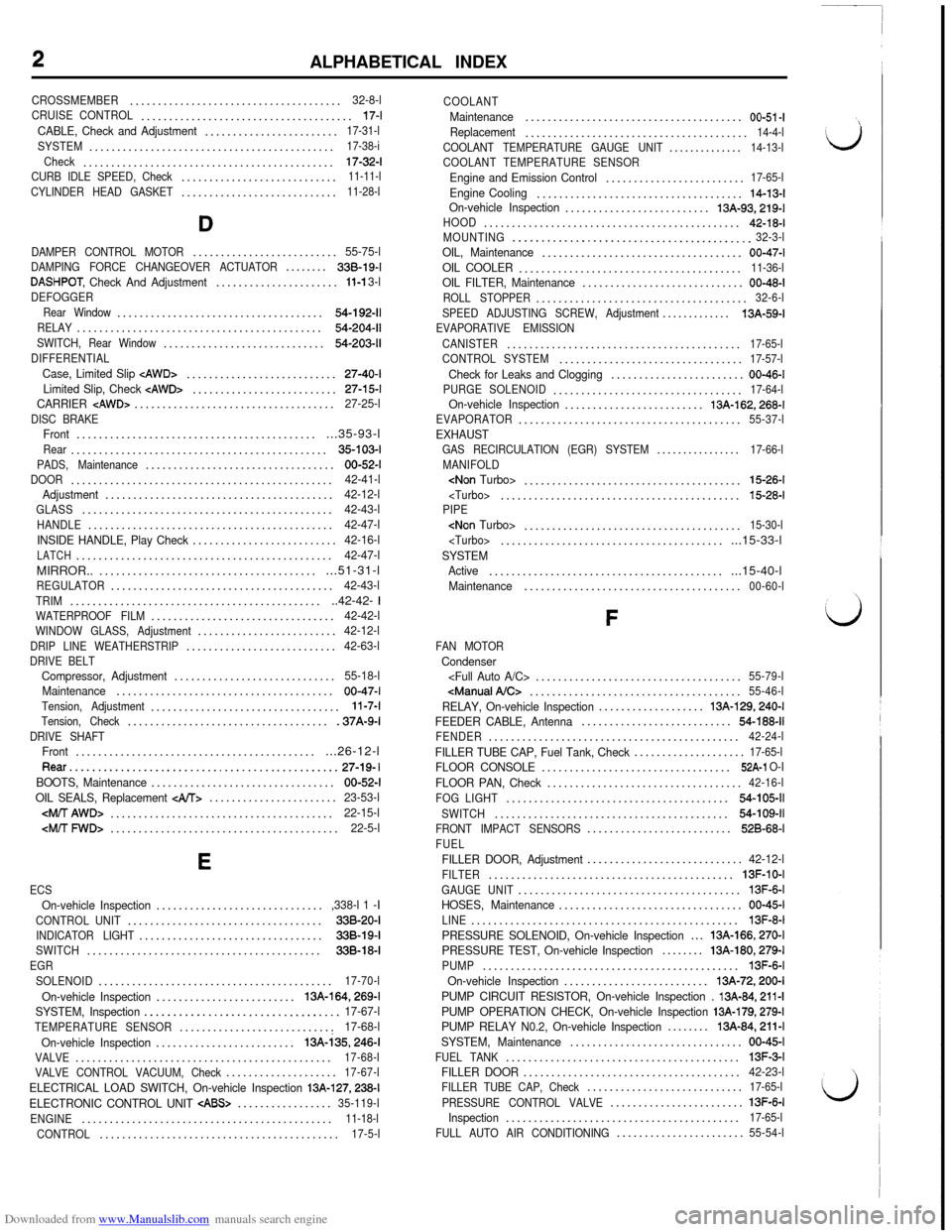
Downloaded from www.Manualslib.com manuals search engine ALPHABETICAL INDEX
CROSSMEMBER......................................32-8-lCRUISE CONTROL......................................17-t
CABLE, Check and Adjustment........................17-31-l
SYSTEM............................................17-38-i
Check.............................................
17-32-l
CURB IDLE SPEED, Check............................11-11-l
CYLINDER HEAD GASKET............................11-28-l
D
DAMPER CONTROL MOTOR..........................55-75-lDAMPING FORCE CHANGEOVER ACTUATOR........338-19-I
DASHPOT, Check And Adjustment......................11-l 3-lDEFOGGER
Rear Window.....................................54-192-11
RELAY............................................54-204-11
SWITCH, Rear Window.............................54-203-11
DIFFERENTIALCase, Limited Slip cAWD>...........................27-40-ILimited Slip, Check cAWD>..........................27-15-tCARRIER
DISC BRAKEFront..............................................35-93-lRear..............................................35-103-I
PADS, Maintenance..................................00-52-I
DOOR...............................................42-41-l
Adjustment.........................................42-12-lGLASS.............................................42-43-l
HANDLE............................................42-47-l
INSIDE HANDLE, Play Check..........................42-16-l
LATCH..............................................42-47-lMIRROR............................................51-31-l
REGULATOR........................................42-43-l
TRIM...............................................42-42- 1WATERPROOF FILM.................................42-42-lWINDOW GLASS, Adjustment.........................42-12-l
DRIP LINE WEATHERSTRIP...........................42-63-lDRIVE BELTCompressor, Adjustment.............................55-18-l
Maintenance.......................................00-47-I
Tension, Adjustment..................................11-7-l
Tension, Check.....................................37A-9-l
DRIVE SHAFTFront..............................................26-12-lRear...............................................27-19- I
BOOTS, Maintenance.................................00-52-l
OIL SEALS, Replacement
.......................23-53-l
E
ECSOn-vehicle Inspection..............................,338-l 1 -I
CONTROL UNIT...................................338-20-IINDICATOR LIGHT.................................338-19-ISWITCH..........................................338-18-I
EGR
SOLENOID..........................................17-70-l
On-vehicle Inspection.........................13A-164,269-l
SYSTEM, Inspection..................................17-67-l
TEMPERATURE SENSOR............................17-68-l
On-vehicle Inspection.........................13A-i35,246-I
VALVE..............................................17-68-l
VALVE CONTROL VACUUM, Check....................17-67-l
ELECTRICAL LOAD SWITCH, On-vehicle Inspection 13A-127,238-l
ELECTRONIC CONTROL UNIT
CABS>.................35-119-l
ENGINE.............................................11-18-l
CONTROL...........................................17-5-lCOOLANT
Maintenance.......................................00-51 -IReplacement........................................14-4-l
COOLANT TEMPERATURE GAUGE UNIT..............14-13-l
COOLANT TEMPERATURE SENSOR
Engine and Emission Control.........................17-65-l
Engine Cooling.....................................14-13-IOn-vehicle Inspection..........................13A-93,219-lHOOD..............................................42-18-l
MOUNTING..........................................32-3-lOIL, Maintenance....................................00-47-l
OIL COOLER........................................11-36-lOIL FILTER, Maintenance.............................00-48-l
ROLL STOPPER......................................32-6-l
SPEED ADJUSTING SCREW, Adjustment.............
13A-59-l
EVAPORATIVE EMISSION
CANISTER..........................................
17-65-l
CONTROL SYSTEM.................................17-57-l
Check for Leaks and Clogging........................00-46-l
PURGE SOLENOID..................................17-64-lOn-vehicle Inspection.........................13A-162,268-lEVAPORATOR........................................55-37-lEXHAUSTGAS RECIRCULATION (EGR) SYSTEM................17-66-l
MANIFOLD
PIPE
SYSTEM
Active.............................................15-40-l
Maintenance.......................................00-60-l
F
FAN MOTORCondenser
RELAY, On-vehicle Inspection...................13A-129.240-t
FEEDER CABLE, Antenna...........................54-188-11FENDER.............................................42-24-l
FILLER TUBE CAP, Fuel Tank, Check....................17-65-lFLOOR CONSOLE..................................52A-1 O-I
FLOOR PAN, Check...................................42-16-l
FOG LIGHT........................................54-105-11
SWITCH..........................................54-109-11FRONT IMPACT SENSORS..........................526-68-l
FUELFILLER DOOR, Adjustment............................42-12-l
FILTER............................................13F-10-I
GAUGE UNIT........................................13F-6-IHOSES, Maintenance.................................00-45-l
LINE................................................13F-8-I
PRESSURE SOLENOID, On-vehicle Inspection...13A-166,270-l
PRESSURE TEST, On-vehicle Inspection........13A-180,279-lPUMP..............................................13F-6-I
On-vehicle Inspection..........................13A-72,200-l
PUMP CIRCUIT RESISTOR, On-vehicle Inspection .
13A-84,211-lPUMP OPERATION CHECK, On-vehicle Inspection 13A-179,279-lPUMP RELAY N0.2, On-vehicle Inspection........13A-84,211-l
SYSTEM, Maintenance...............................00-45-I
FUEL TANK..........................................13F-3-IFILLER DOOR.......................................42-23-lFILLER TUBE CAP, Check............................17-65-l
PRESSURE CONTROL VALVE........................
13F-6-IInspection..........................................17-65-l
FULL AUTO AIR CONDITIONING.......................55-54-l
Page 733 of 738

Downloaded from www.Manualslib.com manuals search engine ALPHABETICAL INDEX3FUNCTION, Check (4WS) .
. . . . . . . . . . . .37B-5-l
GARNISHES . . . . . . . . .
GENERATOR . .
GLASSCenter Pillar .
Door.....................
Door Window, Adjustment
Liftgate . .Quarter Window.Window. . . . . . . . . . . . . . . .G SENSOR.. . . . . .
G
.........................51-15-l........................16-12-11
.....................42-33-l.....................42-43-l......42-12-l......42-38-l......42-34-l......42-26-l....338-l 8-l.....35-117-l
H
HAZARD SWITCH..................................54-110-11
HEADLIGHT........................................54-103-11
HEADLINING.......................................52A-16-l
HEATED OXYGEN SENSOROn-vehicle Inspection.........................13A-137,247-l
HEATER..............................................55-3-l
HEATER CONTROL...................................55-30-I
HEATER UNIT........................................55-34-l
HIGH MOUNTED STOP LIGHT.......................54-107-11
HOOD...............................................42-18-lAdjustment.........................................42-11 -I
HORN.............................................54-115-11RELAY..
..........................................54-118-11
SWITCH..........................................54-118-11
HYDRAULIC UNIT CABS>.............................35-110-I
Check
.............................................35-76-lI
IDLE AIR CONTROL MOTOR (Stepper Motor Type)
On-vehicle Inspection.........................13A-153,263-l
IDLE MIXTURE, Check................................11-12-l
IDLE SPEED
Basic, Adjustment.................................13A-55-lCurb,Check........................................11-11-l
IGNITION
CABLES, Maintenance................................00-46-l
COIL, On-vehicle Inspection....................
13A-158,264-l
POWER TRANSISTOR, On-vehicle Inspection....13&158,264-l
SWITCH............................................54-6-11
SWITCH-IG, On-vehicle Inspection...............13A-65, 193-l
SWITCH-ST, On-vehicle Inspection
......................................13A-113,230-l
SYSTEM...........................................16-45-11
TIMING,‘Check.......................................11-9-l
IMPACT SENSORS, Front............................528-68-I
INDUCTION CONTROL VALVE POSITION SENSOROn-vehicle Inspection.........................13A-133,242-l
INJECTOR........................................13A-286-l
On-vehicle Inspection.........................
13A-144,257-l
INSTRUMENT PANEL.................................52A-5-lINTAKE
AIR TEMPERATURE SENSOR........................17-65-l
On-vehicle Inspection..........................13A-88,215-l
CHARGE PRESSURE CONTROL SYSTEM, Check.......15-7-l
INTAKE MANIFOLD...................................15-17-l
PLENUM
K
KEY INTERLOCK MECHANISM....KEYLESS ENTRY SYSTEM........KICKDOWN SERVO...............KNOCK SENSOR.................On-vehicle Inspection............KNUCKLE........................
.................23-51-l.................42-52-l.................23-47-l..............13A-289-l..........
13A-125,237-l..................26-6-l
L
LASH ADJUSTERSCheck.............................................11-15-lReplacement.......................................11-l 7-l
LATCH, Door.........................................42-47-lLEFT MEMBER........................................32-8-l
LEVER, Shift
cFWD>.............................................22-8-lLICENSE PLATE LIGHT.............................54-106-11
LIFTGATE............................................42-20-I
Adjustment.........................................42-11-l
GLASS.............................................42-38-lLIGHT
Indicator, ECS....................................338-19-IFog.............................................54-105-11Front Combination.................................54-106-11High Mounted Stop................................54-107-11License Plate.....................................54-106-11
Rear Combination.................................54-106-11Switch, Stop......................................33B-19-l
LIGHTING SYSTEM..................................54-35-11LIMITED SLIP DIFFERENTIALCheck cAWD>......................................27-l 5-l
Rear Axle, Oil Change, Maintenance...................00-52-I
CASE
LOOSE PANEL.......................................42-25-l
LOWER ARM
Front Suspension.................................33A-10-I
Rear Suspension
M
MAIN MUFFLER
MANUAL AIR CONDITIONING .
MANUAL TRANSAXLE
cFWD> . . . . . . . . . . . .Maintenance. . . . .
MASTER CYLINDER . . .
Clutch . . . . . . . .
MIRROR, Door..
_. .MIXTURE CONTROL (MFI) SystemMOTOR ANTENNA.. . . .
MOTOR RELAY
CABS>, Check .MOULDINGS . . . . . . . . . . . . .MUFFLER, Main
.....................
.......
...............................................................
..........15-30-I..........
15-33-l...........55-6-l..........
22-13-l...........22-2-l..........00-48-I..........35-87-l..........21-14-l..........51-31-l..........17-70-I........54-188-11..........35-83-l..........51-15-l...........
15-30-I..........15-33-l...
13A-131,241-l
Page 735 of 738

Downloaded from www.Manualslib.com manuals search engine ALPHABETICAL INDEX5
STARTER MOTOR...................................16-23-11STARTING SYSTEM.................................16-19-11
STEERINGAngle Check.........................................37A-6-l
ANGULAR VELOCITY SENSOR.....................338-18-l
GEAR BOX, Power.................................37A-18-l
LINKAGE SEALS, Maintenance........................00-52-I
SHAFT...........................................37A-14-I
STEERING WHEEL.................................37A-14-l
Centering..........................................37A-7-l
Free Play Check
....................................37A-6-l
Return to Center Check..............................37A-9-lSTOP LIGHTHigh Mounted....................................54-107-11SWITCH..........................................338-19-ISTRUT..............................................33A-7-lSUN ROOF...........................................42-56-l
SUSPENSION
RearcAWD>...........................................34-26-l
Fog Light.........................................54-l 09-11Hazard..........................................54-110-11Horn.............................................54-118-11Ignition............................................54-6-11Ignition-lG........................................Refer to I
i
Ignition-ST.......................................Refer to IMuffler Mode Changeover.........................Refer to MParking Brake, Check.................................36-4-lPark/Neutral Position
Power Steering..................................Refer to PRear Window Defogger............................54-203-11Stop Light........................................338-l 9-lT
TAPE PLAYER
ANTI-THEFT SYSTEM..........................THEFT-ALARM SYSTEM.........................THERMOSTAT..................................THROTTLE BODY..............................THROTTLE BODY (Throttle Valve Area), Cleaning...THROTTLE POSITION SENSOR..................Adjustment...................................On-vehicle Inspection..........................TIE ROD END BALL JOINT.......................TIMING BELT...................................Maintenance.................................TIRE..........................................
TRAILING ARMcAWD>......................................
i:
.54-156-11.54-205-11. . . . .14-9-I13A-288-f13A-57-l338-l 9-l13A-57-l13A-98,221 -I. .37A-6-I. . . . .11-31-I. . . . .00-46-I. . . . . .31-4-l
34-32-l. .
34-11-I
.23-64-l22-19, 23-l
. . . . . .22-9-l.00-49-I. .
00-48-l
.23-55-l
OIL COOLER HOSES...............OIL COOLER TUBES................OIL SEAL
FLUID.............................
OILReplacement
TRIM...............................Door..............................TURBOCHARGER
U
UPPER ARM
.............................34-9-l
................22-17-l.................22-6-l.................32-5-l................23-62-l................23-62-l................23-62-l................22-16-l................22-22-l
. . . . . . . . . . . . . . .23-47-l
................22-15-l.................22-4-l...............52A-11-I................42-42-l
................15-20-I................15-23-l.................15-8-l.................15-6-l
.................15-8-l.........13A-169,271-l
V
VACUUM TANK
VAPOR LINE.........................................13F-8-I
VARIABLE INDUCTION CONTROL
MOTOR (DC Motor)...........................13A-174,276-l
SYSTEM, Check......................................15-5-lVEHICLE SPEED SENSORECS.............................................338-l 8-l
On-vehicle Inspection................13A-117, 119,231,233-lVENTILATION........................................55-3-l
SYSTEM, Positive Crankcase..........................17-56-lVALVE, Positive Crankcase............................17-56-lVENTILATORS (Air Inlet and Air Outlet)..................55-52-l
(Instrument Panel)...................................55-50-IVOLUME AIR FLOW SENSOR
Engine and Emission Control.........................17-65-lOn-vehicle Inspection..........................13A-85,212-l
W
..........................................
WASHERRear . . . . . . . . . .
Windshield . . . . . .
WATERPROOF FILM, DoorWATER PUMP . . . . .
WEATHERSTRIP, Drip LineWHEEL . . . .
ALIGNMENT
. . .51-28-I.51-25-l. . .42-42-l. . 14-11-l
. . . . .42-63-l. . .31-4-lFront .
.._.............................Rear
BEARING
. . . . .33A-6-l
. . . . .34-25-l. . . . . .34-5-lAdjustment . . . . . . . . . .. .
.33A-6-t
End Play Check
cFWD>. . . . . . . .27-3-L 34-6-lWHEEL SPEED SENSOR