Page 923 of 976

ENGINE
28
OVERHAUL 6.From all of the readings obtained, determine
highest protrusion figure and select the
appropriate cylinder head gasket.
Protrusion 0.50 to 0.60 mm - select gasket with
1 identification hole.
Protrusion 0.61 to 0.70 mm - select gasket with
2 identification holes.
Protrusion 0.71 to 0.80 mm - select gasket with
3 identification holes.
Protrusion 0.81 to 0.90 mm - select gasket with
0 identification holes.
NOTE: Identification holes are located on
the edge of the gasket.
7.Remove DTI.
8.Rotate crankshaft in a clockwise direction until
all pistons are half-way up cylinder bores.Cylinder head - refit
1.Ensure that mating faces of cylinder head and
block are clean and dry and that 2 locating
dowels are fitted in cylinder block.
2.Lubricate threads of new cylinder head bolts
with engine oil.
3.Check that cylinder head bolt holes in cylinder
block are clean and dry.
4.Rotate crankshaft in a clockwise direction until
pistons are half-way up cylinder bores.
5.Position the selected cylinder head gasket on
cylinder block ensuring that word "TOP" is
facing upwards.
6.Using assistance, fit cylinder head ensuring
that it is located on dowels.
Page 939 of 976
ENGINE
44
OVERHAUL BRAKE SERVO VACUUM PUMP
Remove
1.Ensure that number 1 piston is at TDC.
CAUTION: Rotate crankshaft in a
clockwise direction.
2.Noting their fitted positions, progressively
slacken 5 bolts until all loading is removed from
vacuum pump piston.
NOTE: The sixth bolt was removed during
air cleaner bracket removal.
3.Remove bolts.
4.Remove vacuum pump, remove and discard
gasket.Refit
1.Remove all traces of gasket using suitable
gasket removal spray and a plastic scraper.
2.Ensure number 1 piston is still at TDC.
3.Fit vacuum pump, fit and finger tighten 5 bolts
in their original positions.
NOTE: The sixth bolt is fitted when air
cleaner bracket is fitted.
4.Tighten bolts progressively by diagonal
selection to 25 Nm.
Page 954 of 976

ENGINE
OVERHAUL59
Crankshaft - regrinding
NOTE: Crankshaft journals may be
reground to the following dimensions.
Main bearing journals = 63.225 to 63.237 mm
Big-end bearing journals = 58.475 to 58.494 mm
CAUTION: Rotation of crankshaft must be
in an ANTI-CLOCKWISE direction when
viewed from flywheel end of crankshaft.
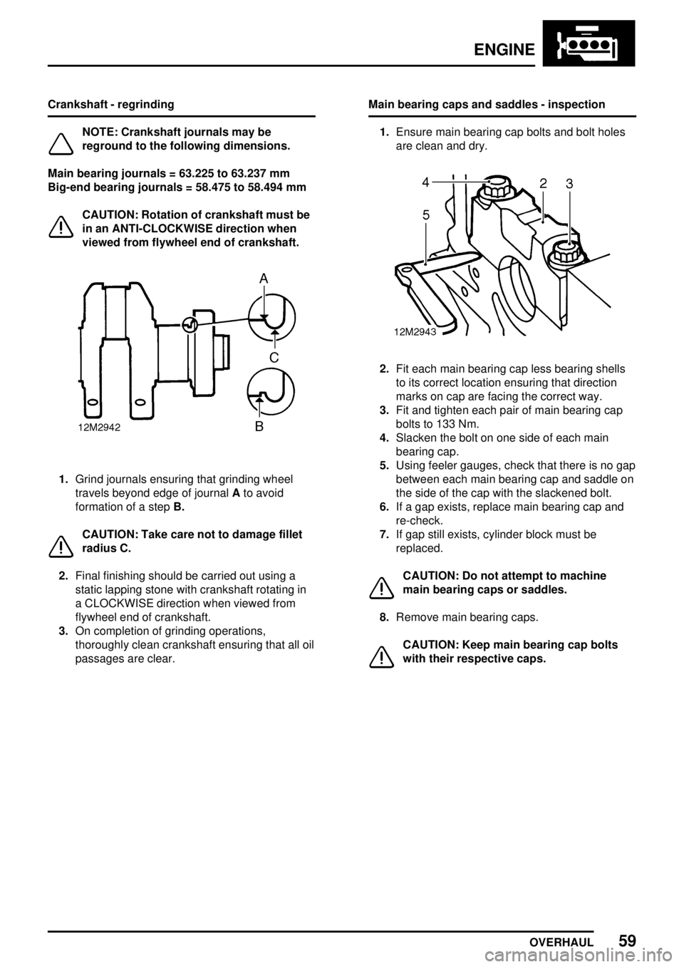
1.Grind journals ensuring that grinding wheel
travels beyond edge of journalAto avoid
formation of a stepB.
CAUTION: Take care not to damage fillet
radius C.
2.Final finishing should be carried out using a
static lapping stone with crankshaft rotating in
a CLOCKWISE direction when viewed from
flywheel end of crankshaft.
3.On completion of grinding operations,
thoroughly clean crankshaft ensuring that all oil
passages are clear.Main bearing caps and saddles - inspection
1.Ensure main bearing cap bolts and bolt holes
are clean and dry.
2.Fit each main bearing cap less bearing shells
to its correct location ensuring that direction
marks on cap are facing the correct way.
3.Fit and tighten each pair of main bearing cap
bolts to 133 Nm.
4.Slacken the bolt on one side of each main
bearing cap.
5.Using feeler gauges, check that there is no gap
between each main bearing cap and saddle on
the side of the cap with the slackened bolt.
6.If a gap exists, replace main bearing cap and
re-check.
7.If gap still exists, cylinder block must be
replaced.
CAUTION: Do not attempt to machine
main bearing caps or saddles.
8.Remove main bearing caps.
CAUTION: Keep main bearing cap bolts
with their respective caps.