1995 LAND ROVER DISCOVERY service
[x] Cancel search: servicePage 866 of 976
86ELECTRICAL
46
REPAIR STARTER MOTOR - 4.0 V8
Service repair no - 86.60.01
Remove
1.Disconnect battery negative lead.
2.Raise vehicle on ramp.
3.Remove heated oxygen sensor from RH front
exhaust pipe.
See EMISSION CONTROL,
Repair, Heated Oxygen Sensor (HO2S) - 4.0
V8
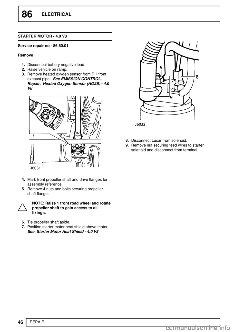
4.Mark front propeller shaft and drive flanges for
assembly reference.
5.Remove 4 nuts and bolts securing propeller
shaft flange.
NOTE: Raise 1 front road wheel and rotate
propeller shaft to gain access to all
fixings.
6.Tie propeller shaft aside.
7.Position starter motor heat shield above motor.
See Starter Motor Heat Shield - 4.0 V8
8.Disconnect Lucar from solenoid.
9.Remove nut securing feed wires to starter
solenoid and disconnect from terminal.
Page 868 of 976
86ELECTRICAL
48
REPAIR STARTER MOTOR HEAT SHIELD - 4.0 V8
Service repair no - 86.60.12
Remove
1.Disconnect battery negative lead.
2.Raise vehicle on ramp.
3.Remove heated oxygen sensor from RH exhaust
front pipe.
See EMISSION CONTROL, Repair,
Heated Oxygen Sensor (HO2S) - 4.0 V8
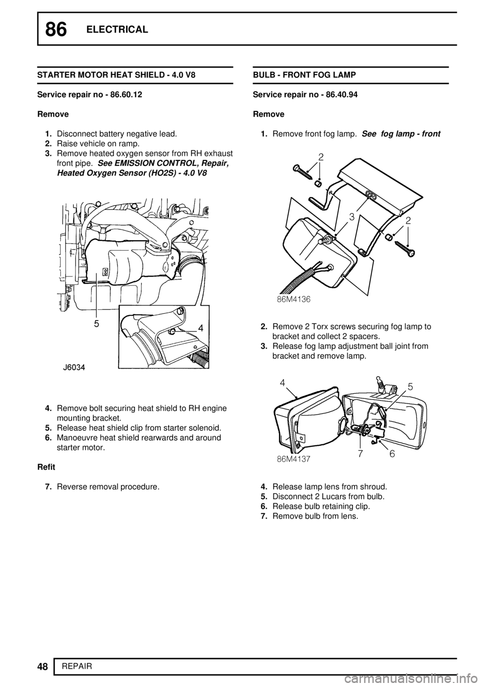
4.Remove bolt securing heat shield to RH engine
mounting bracket.
5.Release heat shield clip from starter solenoid.
6.Manoeuvre heat shield rearwards and around
starter motor.
Refit
7.Reverse removal procedure.BULB - FRONT FOG LAMP
Service repair no - 86.40.94
Remove
1.Remove front fog lamp.
See fog lamp - front
2.Remove 2 Torx screws securing fog lamp to
bracket and collect 2 spacers.
3.Release fog lamp adjustment ball joint from
bracket and remove lamp.
4.Release lamp lens from shroud.
5.Disconnect 2 Lucars from bulb.
6.Release bulb retaining clip.
7.Remove bulb from lens.
Page 869 of 976

ELECTRICAL
49
REPAIR Refit
8.Fit bulb to lens.
9.Secure bulb retaining clip.
10.Connect 2 Lucars to bulb.
11.Position lamp lens to shroud.
12.Position lamp to bracket and secure fog lamp
adjustment ball joint to bracket.
13.Position spacers, align lamp to bracket and
secure with Torx screws.
14.Fit front fog lamp.
See fog lamp - front; Refit
CLOCK
Service repair no - 88.15.07
Remove
1.Remove drinks tray.
See CHASSIS AND
BODY, Repair, drinks tray
2.Release 4 clock panel securing tags.
3.Release clock panel from louvre panel.
4.Disconnect 2 multiplugs from clock.
5.Remove clock.
Refit
6.Position clock.
7.Connect multiplugs to clock and secure clock to
louvre panel.
8.Fit drinks tray.
See CHASSIS AND BODY,
Repair, drinks tray; Refit
REAR SPEAKER
Service repair no - 88.15.12
Remove
1.Remove 4 screws securing speaker.
2.Release speaker and disconnect 2 Lucars.
3.Remove speaker.
Refit
4.Position speaker, connect Lucars and secure
with screws.
Page 870 of 976
86ELECTRICAL
50
REPAIR DIGITAL DIESEL SHUT-OFF VALVE (DDS) - 97 MY
Service repair no - 86.77.00
Remove
1.Remove fuel injection pump.
See FUEL
SYSTEM, Repair, fuel injection pump and
timing
2.Drill into 2 break-off screws to a depth of
approximately 5 mm using a 3.2 mm drill.
CAUTION: Use a drill bushing to guide the
drill during the above.
3.Using an 'Easy-out' remove 2 valve retaining
screws and discard.
4.Release DDS valve from fuel shut-off solenoid.
5.Remove protective cap from fuel shut-off
solenoid electrical connection.
6.Remove fuel shut-off solenoid terminal nut and
remove DDS valve.
Refit
7.Position DDS terminal lead to fuel shut-off
solenoid and secure with nut tightened to
2Nm.
8.Position DDS valve to fuel shut-off solenoid .
9.Position clamping plate to DDS valve and tighten
shear bolts simultaneously until heads shear.
10.Fit fuel injection pump.
See FUEL SYSTEM,
Repair, fuel injection pump and timing; Refit
ANTENNA AMPLIFIER - 97 MY
Service repair no - 86.50.29
Remove
1.Remove RH alpine light trim casing.
See
CHASSIS AND BODY, Repair, alpine light
trim casing
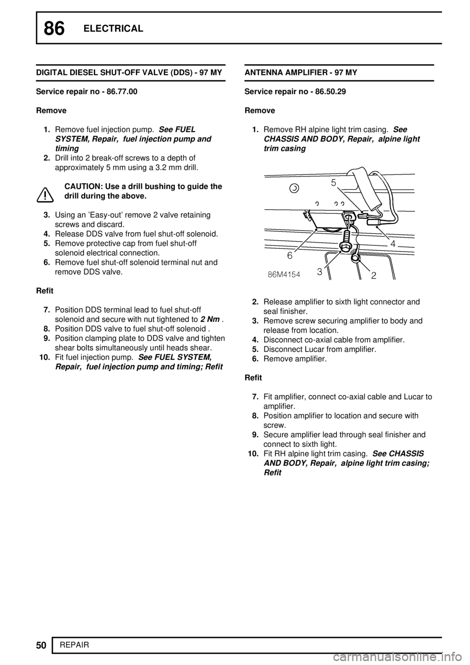
2.Release amplifier to sixth light connector and
seal finisher.
3.Remove screw securing amplifier to body and
release from location.
4.Disconnect co-axial cable from amplifier.
5.Disconnect Lucar from amplifier.
6.Remove amplifier.
Refit
7.Fit amplifier, connect co-axial cable and Lucar to
amplifier.
8.Position amplifier to location and secure with
screw.
9.Secure amplifier lead through seal finisher and
connect to sixth light.
10.Fit RH alpine light trim casing.
See CHASSIS
AND BODY, Repair, alpine light trim casing;
Refit
Page 871 of 976
ELECTRICAL
1
OVERHAUL DISTRIBUTOR-LUCAS 35DLM8
Overhaul
DISTRIBUTOR CAP
Service repair no - 86.35.10
1.Unclip and remove cap
2.Fit a new cap if faulty.
3.Clean cap and HT brush with a lint free cloth.
ROTOR ARM
Service repair no - 86.35.16
1.Pull rotor arm from shaft.
2.Fit a new rotor arm if faulty.
INSULATION COVER (FLASH SHIELD)
Service repair no - 86.35.40
1.Remove cover secured by three screws.
2.Fit a new cover if faulty.
VACUUM UNIT
Service repair no - 86.35.21
1.Remove two screws from vacuum unit securing
bracket. Disengage vacuum unit connecting rod
from pick-up base plate connecting peg.
Withdraw vacuum unit from distributor body.AMPLIFIER MODULE
Service repair no - 86.35.30
1.Remove two screws and withdraw module.
2.Remove gasket.
3.Remove two screws and cast heatsink.
WARNING: Amplifier module is a sealed
unit containing Beryllia. This substance is
extremely dangerous if handled. DO NOT
attempt to open or crush module.
PICK-UP AND BASE PLATE ASSEMBLY
Service repair no - 86.35.42
1.Use circlip pliers to remove circlip retaining
reluctor on rotor shaft.
2.Remove flat washer, and 'O' ring recessed in top
of reluctor.
3.Gently withdraw reluctor from shaft, taking care
not to damage teeth.
NOTE: Coupling ring fitted beneath
reluctor.
4.Remove three support pillars and cable
grommet. Lift out pick-up and base plate
assembly.
NOTE: Do not disturb two barrel nuts
securing pick-up module, otherwise air
gap will need re-adjustment.
5.Fit a new pick-up and base plate assembly if
module is known to be faulty, otherwise check
pick-up winding resistance (2k-5k ohm).
Reassemble
6.This is mainly a reversal of dismantling
procedure, noting following points:
Page 876 of 976
INTRODUCTION
INTRODUCTION1
INTRODUCTION
How to use this manual
To assist in the use of this manual the section title is
given at the top and the relevant sub-section is given
at the bottom each page.
This manual contains procedures for overhaul of the
engine. For all other information regarding
adjustments, removal of oil seals and engine,
consult the Repair Manual for the model concerned.
This manual is divided into 3 sections:
·Description and Operation,
·Overhaul and
·Data, Torque & Tools.
To assist filing of revised information, each
sub-section is numbered from page 1.
Individual items are to be overhauled in the
sequence in which they appear in this Manual. Items
numbered in the illustrations are referred to in the
text.
Overhaul operations include reference to Service
Tool numbers and the associated illustration depicts
the tool. Where usage is not obvious the tool is
shown in use. Operations also include reference to
wear limits, relevant data, torque figures, specialist
information and useful assembly details.
WARNINGS, CAUTIONS and Notes have the
following meanings:
WARNING: Procedures which must be
followed precisely to avoid the possibility
of injury.
CAUTION: Calls attention to procedures
which must be followed to avoid damage
to components.
NOTE: Gives helpful information.References
With the engine and gearbox assembly removed,
the crankshaft pulley end of the engine is referred to
as the front.
Operations covered in this manual do not include
reference to testing the vehicle after repair. It is
essential that work is inspected and tested after
completion and if necessary a road test of the
vehicle is carried out particularly where safety
related items are concerned
Dimensions
The dimensions quoted are to design engineering
specification with Service limits where applicable.
Page 953 of 976
ENGINE
58
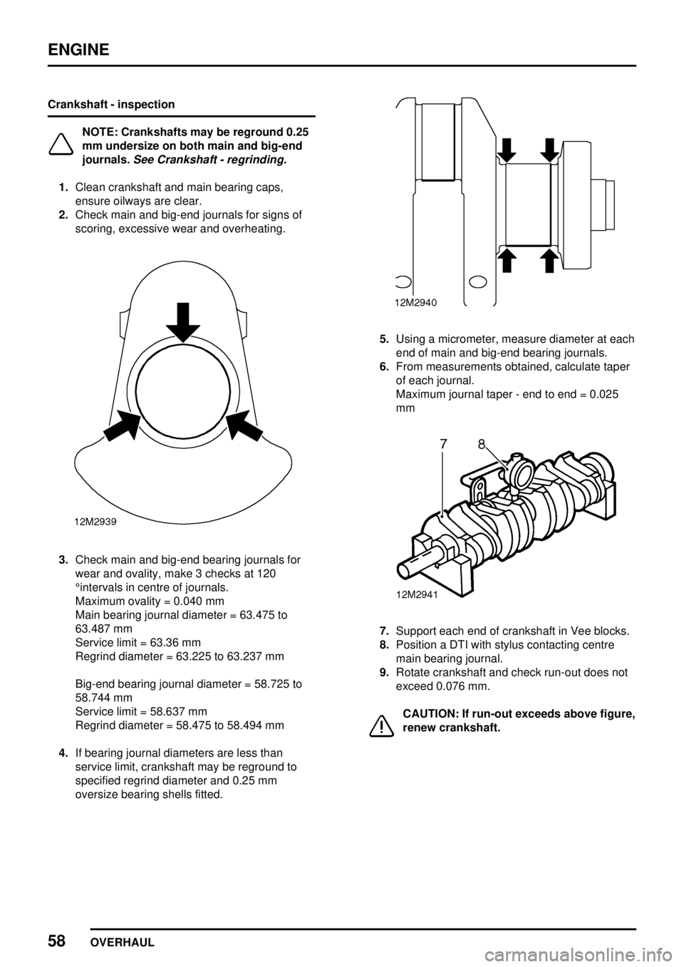
OVERHAUL Crankshaft - inspection
NOTE: Crankshafts may be reground 0.25
mm undersize on both main and big-end
journals.
See Crankshaft - regrinding.
1.Clean crankshaft and main bearing caps,
ensure oilways are clear.
2.Check main and big-end journals for signs of
scoring, excessive wear and overheating.
3.Check main and big-end bearing journals for
wear and ovality, make 3 checks at 120
°intervals in centre of journals.
Maximum ovality = 0.040 mm
Main bearing journal diameter = 63.475 to
63.487 mm
Service limit = 63.36 mm
Regrind diameter = 63.225 to 63.237 mm
Big-end bearing journal diameter = 58.725 to
58.744 mm
Service limit = 58.637 mm
Regrind diameter = 58.475 to 58.494 mm
4.If bearing journal diameters are less than
service limit, crankshaft may be reground to
specified regrind diameter and 0.25 mm
oversize bearing shells fitted.
5.Using a micrometer, measure diameter at each
end of main and big-end bearing journals.
6.From measurements obtained, calculate taper
of each journal.
Maximum journal taper - end to end = 0.025
mm
7.Support each end of crankshaft in Vee blocks.
8.Position a DTI with stylus contacting centre
main bearing journal.
9.Rotate crankshaft and check run-out does not
exceed 0.076 mm.
CAUTION: If run-out exceeds above figure,
renew crankshaft.
Page 974 of 976
ENGINE
2
DATA, TORQUE & TOOLS Crankshaft
Maximum bearing journal ovality 0.040 mm................
Maximum bearing journal run-out 0.076 mm...............
Main bearing journal diameter 63.475 to 63.487 mm..................
Service limit 63.36 mm................................
Regrind diameter 63.225 to 63.237 mm............................
Big-end journal diameter 58.725 to 58.744 mm......................
Service limit 58.637 mm................................
Regrind diameter 58.475 to 58.494 mm............................
Main and big-end bearing oversizes available 0.25 mm......
Main bearing clearance 0.031 to 0.079 mm.......................
Crankshaft end-float 0.05 to 0.15 mm.........................
Thrust washer oversizes available:
1st oversize 0.063................................
2nd oversize 0.127 mm...............................
Big-end bearing clearance 0.025 to 0.075 mm.....................
Connecting rod end-float 0.15 to 0.35 mm......................
Camshaft
End-float 0.1 to 0.2 mm..................................
Pistons and connecting rods
Piston diameter:
Standard 90.395 mm..................................
1st oversize 90.649 mm................................
2nd oversize 90.903 mm...............................
Piston to cylinder bore clearance 0.075 mm................
Connecting rod misalignment - maximum 0.075 mm per 25.4 mm.........
Piston rings
Fitted gap in cylinder bore:
Top compression 0.40 to 0.65 mm............................
2nd compression 0.30 to 0.50 mm............................
Oil control rails 0.30 to 0.60 mm..............................
Ring to groove clearance:
Top compression 0.167 to 0.232 mm............................
2nd compression 0.05 to 0.08 mm............................
Oil control ring assembly 0.05 to 0.08 mm......................
Cylinder block
Cylinder bore maximum ovality 0.127 mm.................
Cylinder bore maximum taper 0.254 mm..................
Cylinder bore maximum wear 0.177 mm..................
Cylinder bore size:
Standard 90.47 mm..................................
For 1st oversize piston 90.73 mm.......................
For 2nd oversize piston 90.98 mm.......................