Page 956 of 976
ENGINE
OVERHAUL61
Crankshaft end-float - checking
1.Lubricate upper main bearing shells and
crankshaft main bearing journals with engine
oil.
2.Lubricate new standard size thrust washers
with engine oil and position washers in recess
in centre main bearing saddle.
NOTE: Grooved side of washers must face
outwards.
3.Using assistance, fit crankshaft.
4.Attach a DTI to rear face of cylinder block with
stylus contacting end of crankshaft; push
crankshaft fully rearwards and zero gauge.
5.Push crankshaft fully forwards and measure
end-float.
6.If end-float exceeds 0.05 to 0.15 mm, remove
crankshaft, fit combinations of standard and
oversize thrust washers to achieve correct
end-float.
CAUTION: Variations of thrust washer
thicknesses on each side of crankshaft
must not exceed 0.08 mm.
7.When end-float is correct, remove DTI.
8.Using assistance, remove crankshaft and
thrust washers. Ensure that thrust washers are
identified to their location.
Page 957 of 976
ENGINE
62
OVERHAUL Big-end bearing clearance - checking
1.Fit pistons and connecting rods.
2.Degrease new big-end bearing shells.
3.Fit big-end bearing shells to connecting rods
ensuring that tag is located in recess in
connecting rod.
4.Fit big-end bearing shells to bearing caps
ensuring that tag is located in recess in cap.
5.Temporarily fit crankshaft pulley bolt and rotate
crankshaft to bring numbers 1 and 4 journals to
BDC.
6.Remove all traces of oil from crankshaft
journals.
7.Pull numbers 1 and 4 connecting rods on to
crankshaft journals, remove plastic tubing from
connecting rod bolts.
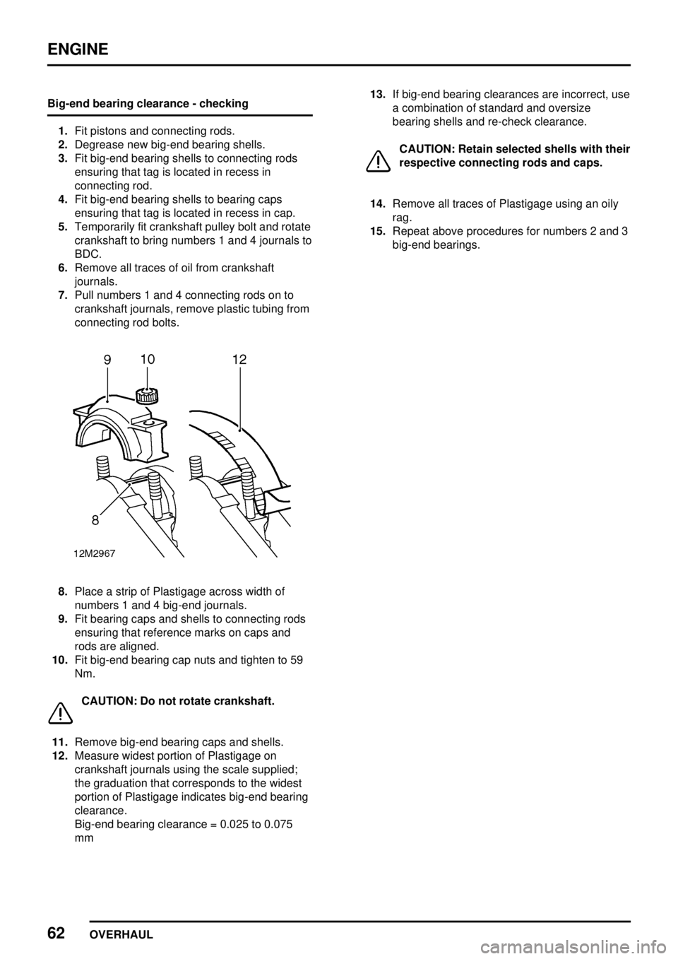
8.Place a strip of Plastigage across width of
numbers 1 and 4 big-end journals.
9.Fit bearing caps and shells to connecting rods
ensuring that reference marks on caps and
rods are aligned.
10.Fit big-end bearing cap nuts and tighten to 59
Nm.
CAUTION: Do not rotate crankshaft.
11.Remove big-end bearing caps and shells.
12.Measure widest portion of Plastigage on
crankshaft journals using the scale supplied;
the graduation that corresponds to the widest
portion of Plastigage indicates big-end bearing
clearance.
Big-end bearing clearance = 0.025 to 0.075
mm13.If big-end bearing clearances are incorrect, use
a combination of standard and oversize
bearing shells and re-check clearance.
CAUTION: Retain selected shells with their
respective connecting rods and caps.
14.Remove all traces of Plastigage using an oily
rag.
15.Repeat above procedures for numbers 2 and 3
big-end bearings.
Page 958 of 976
ENGINE
OVERHAUL63
Crankshaft, main and big-end bearings - refit
Crankshaft and main bearings
CAUTION: Cylinder bores must be
inspected before crankshaft is refitted -
See cylinder block - inspection
1.Lubricate selected main bearing shells, thrust
washers and crankshaft journals with engine
oil, ensure bolt holes in bearing saddles are
clean and dry; fit bearing shells in main bearing
caps and saddles.
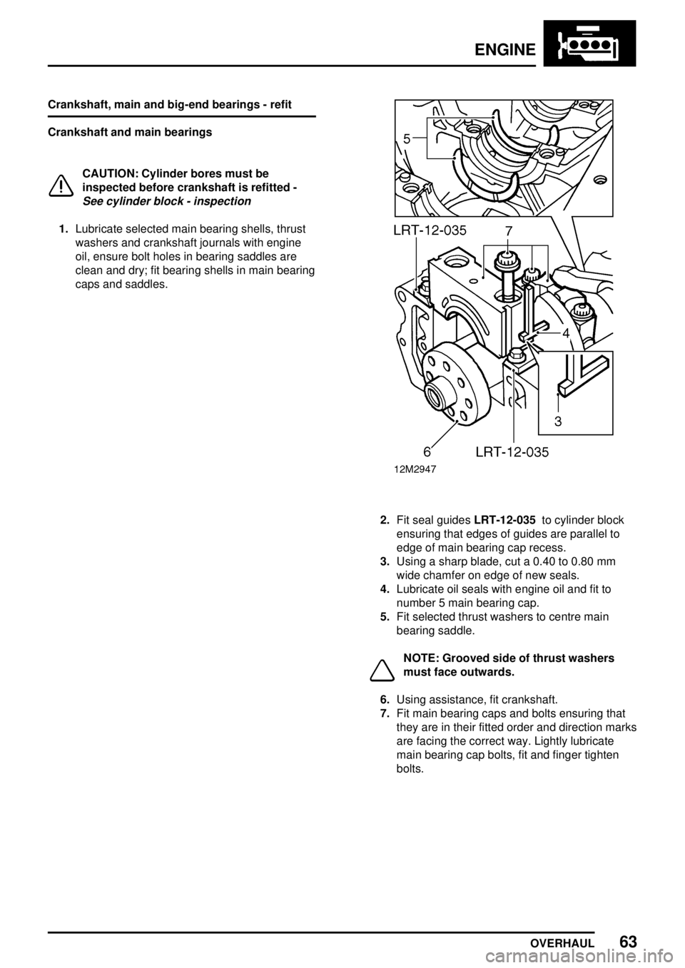
2.Fit seal guidesLRT-12-035to cylinder block
ensuring that edges of guides are parallel to
edge of main bearing cap recess.
3.Using a sharp blade, cut a 0.40 to 0.80 mm
wide chamfer on edge of new seals.
4.Lubricate oil seals with engine oil and fit to
number 5 main bearing cap.
5.Fit selected thrust washers to centre main
bearing saddle.
NOTE: Grooved side of thrust washers
must face outwards.
6.Using assistance, fit crankshaft.
7.Fit main bearing caps and bolts ensuring that
they are in their fitted order and direction marks
are facing the correct way. Lightly lubricate
main bearing cap bolts, fit and finger tighten
bolts.
Page 959 of 976
ENGINE
64
OVERHAUL 8.Tighten centre main bearing cap bolts to 133
Nm.
9.Temporarily fit crankshaft pulley bolt and check
that crankshaft rotates freely and smoothly.
10.Tighten each pair of main bearing cap bolts to
133 Nm in the order No. 2, No. 4, No. 1 and
No. 5. Check that crankshaft rotates freely and
smoothly after tightening each pair of bolts.
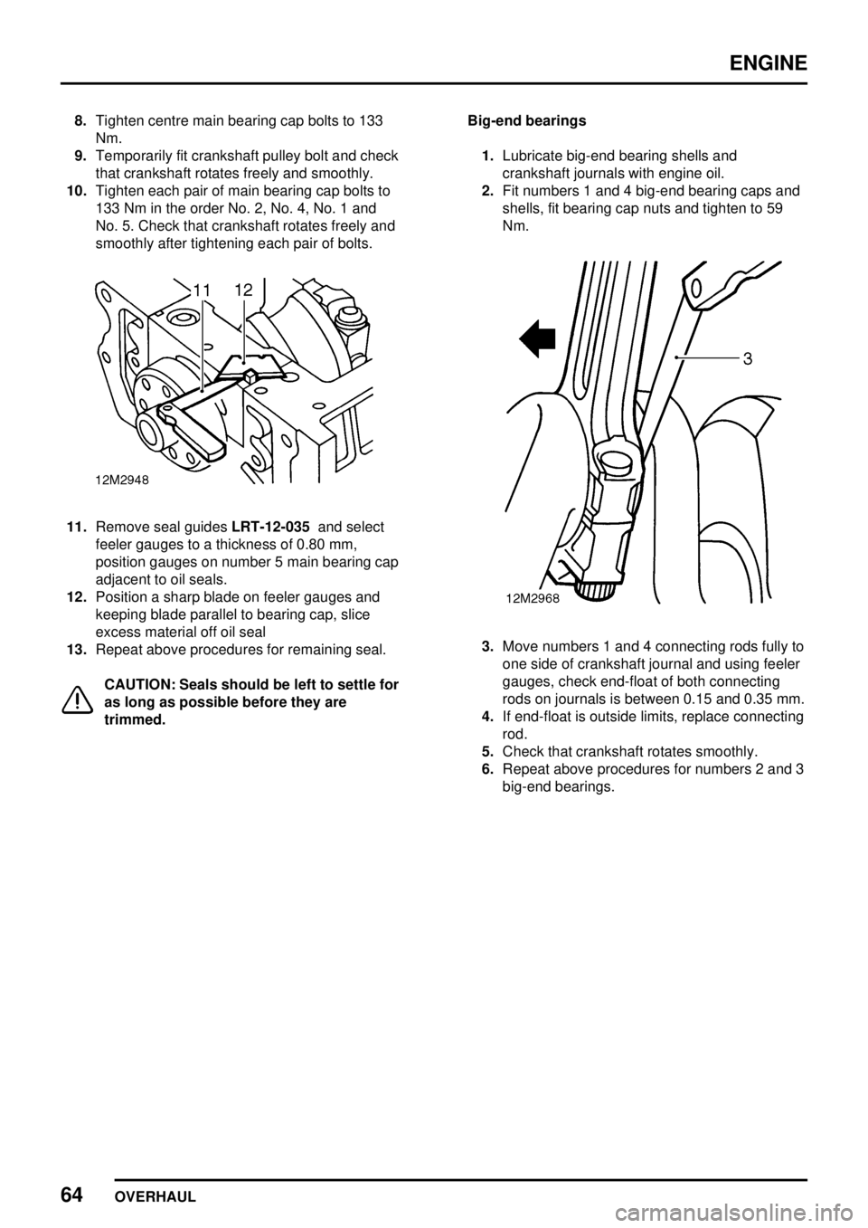
11.Remove seal guidesLRT-12-035and select
feeler gauges to a thickness of 0.80 mm,
position gauges on number 5 main bearing cap
adjacent to oil seals.
12.Position a sharp blade on feeler gauges and
keeping blade parallel to bearing cap, slice
excess material off oil seal
13.Repeat above procedures for remaining seal.
CAUTION: Seals should be left to settle for
as long as possible before they are
trimmed.Big-end bearings
1.Lubricate big-end bearing shells and
crankshaft journals with engine oil.
2.Fit numbers 1 and 4 big-end bearing caps and
shells, fit bearing cap nuts and tighten to 59
Nm.
3.Move numbers 1 and 4 connecting rods fully to
one side of crankshaft journal and using feeler
gauges, check end-float of both connecting
rods on journals is between 0.15 and 0.35 mm.
4.If end-float is outside limits, replace connecting
rod.
5.Check that crankshaft rotates smoothly.
6.Repeat above procedures for numbers 2 and 3
big-end bearings.
Page 960 of 976
ENGINE
OVERHAUL65
Crankshaft rear oil seal - refit
1.Ensure that oil seal running surface on
crankshaft and oil seal housing mating surface
on cylinder block are clean and oil free and that
bolt holes in cylinder block are clean and dry.
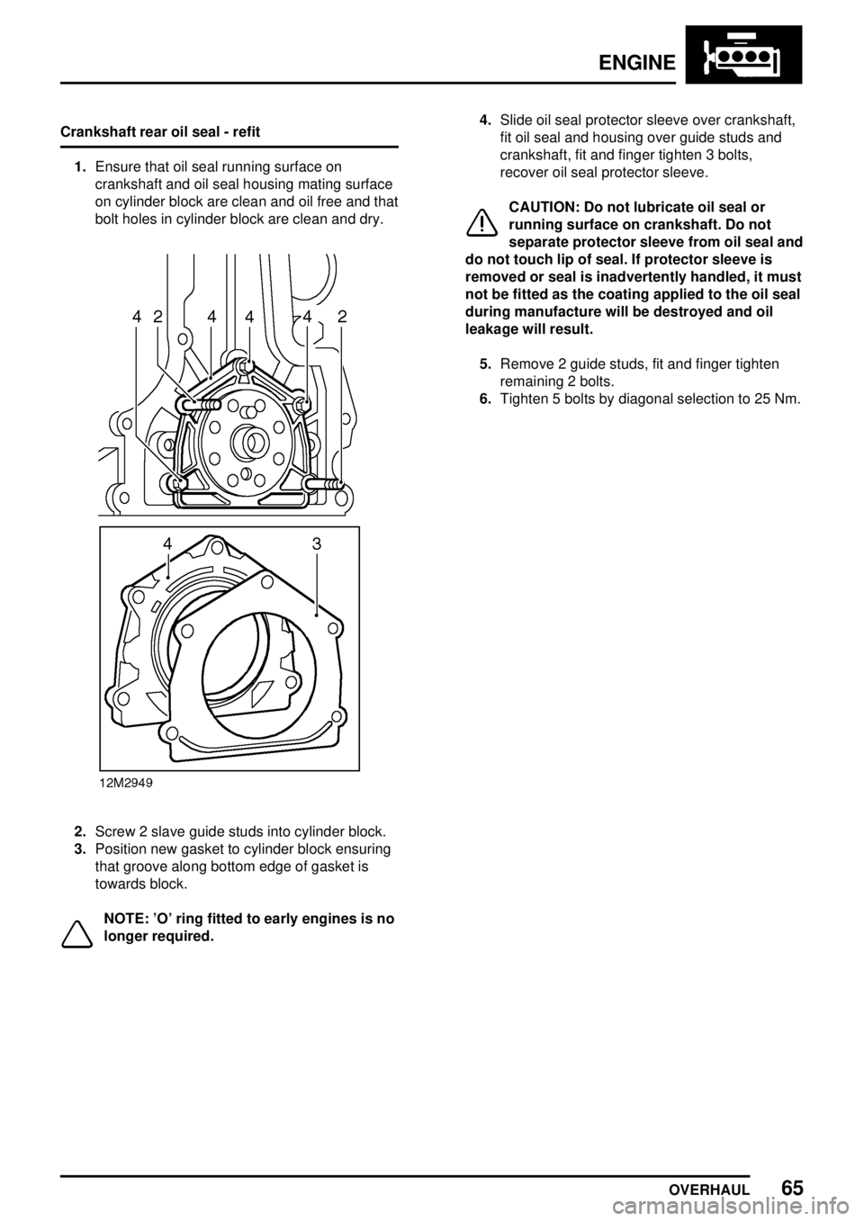
2.Screw 2 slave guide studs into cylinder block.
3.Position new gasket to cylinder block ensuring
that groove along bottom edge of gasket is
towards block.
NOTE: 'O' ring fitted to early engines is no
longer required.4.Slide oil seal protector sleeve over crankshaft,
fit oil seal and housing over guide studs and
crankshaft, fit and finger tighten 3 bolts,
recover oil seal protector sleeve.
CAUTION: Do not lubricate oil seal or
running surface on crankshaft. Do not
separate protector sleeve from oil seal and
do not touch lip of seal. If protector sleeve is
removed or seal is inadvertently handled, it must
not be fitted as the coating applied to the oil seal
during manufacture will be destroyed and oil
leakage will result.
5.Remove 2 guide studs, fit and finger tighten
remaining 2 bolts.
6.Tighten 5 bolts by diagonal selection to 25 Nm.
Page 961 of 976
ENGINE
66
OVERHAUL Pistons and connecting rods - remove
1.Remove big-end bearings.
2.Suitably identify each piston to its respective
cylinder bore, check that arrow on piston crown
is pointing towards front of cylinder block; if
arrow is not visible, suitably mark piston.
3.Check that plastic tubing is fitted to connecting
rod bolts.
4.Push each piston and connecting rod up
cylinder bore until they can be withdrawn.
5.Remove big-end bearing shells from
connecting rods.
CAUTION: Big-end bearing shells should
always be renewed.
6.Inspect pistons and connecting rods.Piston rings - remove
1.Using a suitable expander, remove and discard
piston rings.
2.Using a squared-off end of an old piston ring,
remove carbon from piston ring grooves.
Page 962 of 976
ENGINE
OVERHAUL67
Pistons - remove
1.Suitably identify each piston to its connecting
rod, note position of bearing shell tag recess in
connecting rod relative to arrow on piston
crown.
2.Remove and discard circlips retaining gudgeon
pin.
3.Push gudgeon pin out of piston, remove
connecting rod. Retain gudgeon pins and
connecting rods with their respective pistons.Pistons and connecting rods - inspection
1.Remove carbon from piston using fine emery
cloth soaked in oil.
2.Measure and record piston diameter at right
angles to gudgeon pin hole mid-way between
hole and bottom of skirt.
Piston diameter:
Standard = 90.395 mm
1st oversize = 90.649 mm
2nd oversize = 90.903 mm
Page 963 of 976
ENGINE
68
OVERHAUL
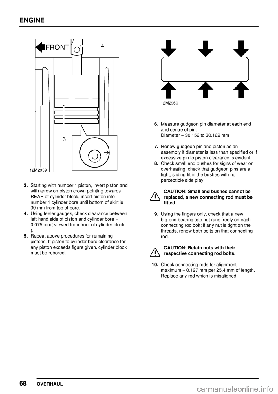
3.Starting with number 1 piston, invert piston and
with arrow on piston crown pointing towards
REAR of cylinder block, insert piston into
number 1 cylinder bore until bottom of skirt is
30 mm from top of bore.
4.Using feeler gauges, check clearance between
left hand side of piston and cylinder bore =
0.075 mm( viewed from front of cylinder block
).
5.Repeat above procedures for remaining
pistons. If piston to cylinder bore clearance for
any piston exceeds figure given, cylinder block
must be rebored.
6.Measure gudgeon pin diameter at each end
and centre of pin.
Diameter = 30.156 to 30.162 mm
7.Renew gudgeon pin and piston as an
assembly if diameter is less than specified or if
excessive pin to piston clearance is evident.
8.Check small end bushes for signs of wear or
overheating, check that gudgeon pins are a
tight, sliding fit in the bushes with no
perceptible side play.
CAUTION: Small end bushes cannot be
replaced, a new connecting rod must be
fitted.
9.Using the fingers only, check that a new
big-end bearing cap nut runs freely on each
connecting rod bolt; if any nut is tight on the
threads, renew both bolts on that connecting
rod.
CAUTION: Retain nuts with their
respective connecting rod bolts.
10.Check connecting rods for alignment -
maximum = 0.127 mm per 25.4 mm of length.
Replace any rod which is misaligned.