Page 904 of 976
ENGINE
OVERHAUL9
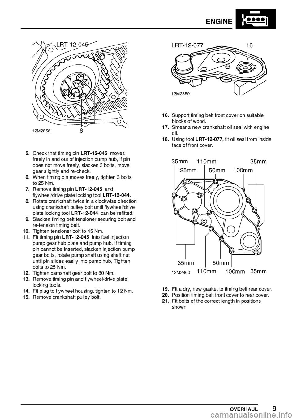
5.Check that timing pinLRT-12-045moves
freely in and out of injection pump hub, if pin
does not move freely, slacken 3 bolts, move
gear slightly and re-check.
6.When timing pin moves freely, tighten 3 bolts
to 25 Nm.
7.Remove timing pinLRT-12-045and
flywheel/drive plate locking toolLRT-12-044.
8.Rotate crankshaft twice in a clockwise direction
using crankshaft pulley bolt until flywheel/drive
plate locking toolLRT-12-044can be refitted.
9.Slacken timing belt tensioner securing bolt and
re-tension timing belt.
10.Tighten tensioner bolt to 45 Nm.
11.Fit timing pinLRT-12-045into fuel injection
pump gear hub plate and pump hub. If timing
pin cannot be inserted, slacken injection pump
gear bolts, rotate pump shaft using shaft nut
until pin slides easily into pump hub, Tighten
bolts to 25 Nm.
12.Tighten camshaft gear bolt to 80 Nm.
13.Remove timing pin and flywheel/drive plate
locking tools.
14.Fit plug to flywheel housing, tighten to 12 Nm.
15.Remove crankshaft pulley bolt.
16.Support timing belt front cover on suitable
blocks of wood.
17.Smear a new crankshaft oil seal with engine
oil.
18.Using toolLRT-12-077,fit oil seal from inside
face of front cover.
19.Fit a dry, new gasket to timing belt rear cover.
20.Position timing belt front cover to rear cover.
21.Fit bolts of the correct length in positions
shown.
Page 916 of 976
ENGINE
OVERHAUL21
Valve springs - inspection
1.Check free length of each spring = 46.28 mm
2.Check that end coils of each spring are square
to body of spring.Valves and guides - inspection
1.Remove carbon from valves.
2.Examine head of each valve for cracks and
burning and valve seat for pitting or burning,
replace valves as necessary.
3.Check valve seating faces for pitting, if light
pitting cannot be removed during valve
grinding operations, valves may be refaced.
CAUTION: If refacing results in valve head
stand down being exceeded, valves must
be replaced.
4.Check valve seating face angles.
Inlet = 60°00' to 60°30' - included angle =120
°
Exhaust = 45°00' to 45°30' - included angle =
90°
5.Reface or replace valves as necessary.
6.Check each valve stem for wear, measure at
each end and centre of valve stem.
Inlet = 7.96 mm
Exhaust = 7.94 mm
7.Replace any valve with stems that are worn.
Page 924 of 976
ENGINE
OVERHAUL29
7.Fit cylinder head bolts of the correct length in
positions shown.
CAUTION: Do not drop bolts into cylinder
block.
8.Tighten bolts until bolt heads just contact
cylinder head.
9.Using sequence shown, tighten cylinder head
bolts to 40 Nm.
Page 927 of 976
ENGINE
32
OVERHAUL Oil pressure relief valve
1.Remove plug retaining oil pressure relief valve.
2.Withdraw spring and plunger.Inspecting components
1.Check rotor clearances.
A- Outer rotor to housing = 0.025 to 0.075 mm
B- Inner rotor to outer rotor = 0.025 to 0.075
mm
C- Rotor end-float = 0.026 to 0.135 mm
2.Remove inner and outer rotors.
3.Check rotors for damage, wear and scoring.
4.Check oil pump cover for wear and scoring.
5.Check oil pressure relief valve spring free
length is 68.0 mm.
6.Check plunger and relief valve bore for wear
and scoring.
7.Clean all traces of sealant from oil pump cover
using solvent from kit GUG 705548GM.
8.Remove all traces of sealant from relief valve
plug threads in oil pump body.
CAUTION: Do not use a tap.
Page 929 of 976
ENGINE
34
OVERHAUL Timing belt rear cover - refit
1.Remove all traces of gasket material from
cylinder block using suitable gasket removal
spray and a plastic scraper.
2.Screw 2 slave guide studs into cylinder block.
3.Fit new gasket over guide studs.
4.Note position of oil pump drive flats on
crankshaft.
5.Rotate oil pump inner rotor to align with drive
flats on crankshaft and position timing belt rear
cover on guide studs.
6.Fit timing belt rear cover.
CAUTION: Do not remove guide studs at
this stage.
7.Fit 8 bolts of the correct length in positions
shown, remove guide studs and fit remaining 2
bolts.
Page 963 of 976
ENGINE
68
OVERHAUL
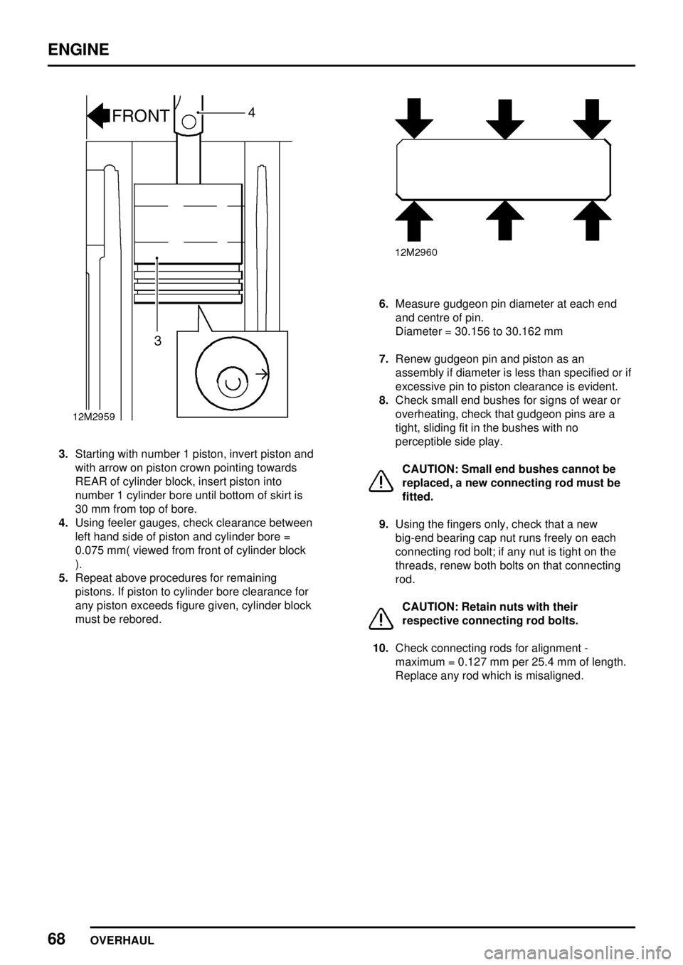
3.Starting with number 1 piston, invert piston and
with arrow on piston crown pointing towards
REAR of cylinder block, insert piston into
number 1 cylinder bore until bottom of skirt is
30 mm from top of bore.
4.Using feeler gauges, check clearance between
left hand side of piston and cylinder bore =
0.075 mm( viewed from front of cylinder block
).
5.Repeat above procedures for remaining
pistons. If piston to cylinder bore clearance for
any piston exceeds figure given, cylinder block
must be rebored.
6.Measure gudgeon pin diameter at each end
and centre of pin.
Diameter = 30.156 to 30.162 mm
7.Renew gudgeon pin and piston as an
assembly if diameter is less than specified or if
excessive pin to piston clearance is evident.
8.Check small end bushes for signs of wear or
overheating, check that gudgeon pins are a
tight, sliding fit in the bushes with no
perceptible side play.
CAUTION: Small end bushes cannot be
replaced, a new connecting rod must be
fitted.
9.Using the fingers only, check that a new
big-end bearing cap nut runs freely on each
connecting rod bolt; if any nut is tight on the
threads, renew both bolts on that connecting
rod.
CAUTION: Retain nuts with their
respective connecting rod bolts.
10.Check connecting rods for alignment -
maximum = 0.127 mm per 25.4 mm of length.
Replace any rod which is misaligned.
Page 967 of 976
ENGINE
72
OVERHAUL Pistons and connecting rods - refit
1.Position piston ring gaps at 60°to each other
and away from thrust side of piston (left hand
side of piston when viewed from front).
2.Slide suitable lengths of tubing over connecting
rod bolts.
3.Ensure cylinder bores are clean.
4.Lubricate pistons, rings and cylinder bores with
engine oil.
5.Compress piston rings using a suitable clamp.
6.Insert piston and connecting rod into cylinder
bore ensuring that piston is in its correct fitted
order and arrow on piston crown is towards
front of cylinder block.
7.Push piston into cylinder bore.
CAUTION: Ensure that connecting rods do
not contact cylinder bores. Do not pull
connecting rods fully down cylinder bores
at this stage.
8.Repeat above procedures for numbers 2 and 3
pistons and connecting rods.Oil jet tubes - refit
1.Position sealing washers in cylinder block.
2.Fit oil jet tubes to their original locations.
3.Fit banjo bolts and washers, tighten bolts to 17
Nm.
Page 973 of 976

ENGINE
DATA, TORQUE & TOOLS1
ENGINE DATA
Rocker shaft
Rocker shaft wear - maximum 0.025 mm..................
Rocker arm shaft to bush clearance - maximum 0.12 mm....
Valve clearance - inlet and exhaust 0.20 mm..............
Oil pump
Outer rotor to housing clearance 0.025 to 0.075 mm................
Inner to outer rotor clearance 0.025 to 0.075 mm..................
Outer rotor end-float 0.026 to 0.135 mm.........................
Relief valve spring free length 68.0 mm..................
Cylinder head
Cylinder head maximum warpage 0.08 mm...............
Maximum movement of valve to guide 0.15 mm...........
Valve stem diameter:
Inlet 7.96 mm......................................
Exhaust 7.94 mm...................................
Valve head stand down:
Inlet 0.81 to 1.09 mm......................................
Exhaust 0.86 to 1.14 mm...................................
Valve seat insert face angle:
Inlet 60° ......................................
Exhaust 45° ...................................
Valve face angle:
Inlet 60°00' to 60°30' ......................................
Exhaust 45°00' to 45°30' ...................................
Valve spring free length 46.28 mm.......................
Timing belt tension on torque wrench
Used belt 12 Nm..................................
New belt 15 Nm...................................
Drive plate - automatic gearbox
Setting height 12.4 mm...............................


