Page 863 of 976
ELECTRICAL
43
REPAIR ANTI-THEFT ALARM ECU (96 MODELS)
Service repair no - 86.55.85
Remove
1.Remove 4 studs securing fascia left hand
closing panel.
2.Remove closing panel.
3.Disconnect 2 multiplugs from ECU.
4.Remove nut securing ECU/relay bracket.
5.Lower bracket.
6.Remove 2 nuts securing ECU to bracket.
7.Remove ECU.
NOTE: A new ECU must be initialised
using TestBook.
Refit
8.Reverse removal procedure.HANDSET (96 MODELS)
If vehicle does not respond to handset immediately, it
may have lost synchronisation. To re-synchronise,
press either button, 4 times in quick succession. If
handset still fails to respond, check batteries, refer to
Owner's handbook. If batteries are okay, it may be
necessary to use emergency key access, refer to
Owner's handbook.
NOTE: New handsets must be initialised
using TestBook.
PASSIVE COIL (96 MODELS)
Service repair no - 86.77.35
Remove
1.Remove steering column shroud.
See
STEERING, Repair, Steering column shroud
2.Release multiplug from harness clip and
disconnect.
3.Release passive coil from starter switch.
4.Remove bulb holder/starter switch shroud.
5.Remove coil.
Refit
6.Fit coil, ensuring switch illumination bulb harness
passes through large cut-out.
7.Secure coil with cable tie.
8.Position bulb holder/starter switch shroud and
locate bulb.
9.Locate bulb holder/starter switch shroud,
ensuring cut-out in shroud aligns with lug on
starter switch.
10.Connect multiplug and secure to clip.
11.Fit column shroud.
Page 909 of 976
ENGINE
14
OVERHAUL Rocker shaft - assembling
1.Lubricate all components with engine oil.
2.Assemble rocker arms, spacers, washers and
pedestals to rocker shaft ensuring that they are
in their original fitted positions.
3.Retain pedestals 1 and 5 with slave bolts.Rocker shaft - refit
1.Lubricate push rods with engine oil and fit to
their original positions. Ensure that ball end of
each push rod is correctly located in each cam
follower slide.
2.Screw each tappet adjusting screw into its
respective rocker arm until ball end is flush with
underside of arm; fit but do not tighten
locknuts.
3.Lubricate valve pads with engine oil and fit to
their original positions.
4.Position rocker shaft to cylinder head, fit but do
not tighten 3 nuts.
5.Remove slave bolts from pedestals 1 and 5, fit
but do not tighten 2 bolts.
6.Locate each push rod in turn beneath its
respective tappet adjusting screw and tighten
each screw until ball end locates in recess in
push rod.
7.Working from the centre outwards,
progressively tighten 3 nuts and 2 bolts to 5
Nm.
Page 921 of 976
ENGINE
26
OVERHAUL Lapping-in valves
1.Lap each valve to its seat using grinding paste.
2.Apply Prussian Blue to valve seat insert. Insert
valve into guide and press it firmly, without
rotating on to seat.
3.Remove valve and check that a continuous,
even line of Prussian Blue has been
transferred to valve face, continue lapping-in
valve as necessary.
NOTE: Line does not have to be across
whole width of valve face.
4.Remove all traces of grinding paste on
completion.
5.Check valve head stand down of each valve.Valve head stand down - checking
1.Insert each valve into its respective guide.
2.Using a straight edge and feeler gauges, check
and record stand down of each valve head.
3.Compare figures obtained with those given
below. If any valve head has a stand down
outside that specified, valve and/or seat insert
must be replaced.
Valve head stand down:
Inlet valveA= 0.81 to 1.09 mm
Exhaust valveB= 0.86 to 1.14 mm
Page 922 of 976
ENGINE
OVERHAUL27
Valves and springs - refit
1.Lubricate valve stems, guides, spring seats,
valve springs, spring cups and collets with
engine oil.
2.Lubricate new valve stem oil seals with engine
oil and fit to valve guides.
3.Fit spring seat, insert valve into its respective
guide, fit valve spring and spring cup.
4.Compress valve spring using toolLRT-12-034
and fit collets.
5.Remove toolLRT-12-034.
6.Tap spring cup with a soft mallet to ensure that
collets are correctly seated.
7.Repeat above procedures for remaining
valves.Cylinder head gasket selection
CAUTION: New cylinder head gasket
should be same thickness as the original.
If, however, cylinder head, pistons or
crankshaft have been replaced, it will be
necessary to check piston stand proud in order
to determine the correct thickness of gasket.
1.Position a magnetic base DTI to cylinder block
top face adjacent to number 1 cylinder bore.
2.Position stylus of gauge to cylinder block top
face on edge of number 1 cylinder bore; zero
gauge.
3.Rotate crankshaft in a clockwise direction until
numbers 1 and 4 pistons are at TDC.
4.Position stylus of DTI gauge near edge of
piston crown, measure and record number 1
piston stand proud. Measurement must be
taken at front and rear of piston and highest
protrusion figure recorded.
5.Repeat above procedures for remaining
pistons.
Page 951 of 976
ENGINE
56
OVERHAUL Big-end bearings - remove
1.Suitably identify each oil jet tube to its fitted
location.
2.Remove bolt securing each oil jet tube
assembly to cylinder block.
3.Remove oil jet tube assemblies.
NOTE: Dowel located.
4.Recover sealing washers.
CAUTION: Oil jet tube bolts incorporate a
non-return valve.
5.Temporarily fit crankshaft pulley bolt.
6.Suitably identify fitted position of each big-end
bearing cap to its connecting rod and each
connecting rod to its respective cylinder bore.
7.Rotate crankshaft to bring numbers 1 and 4
connecting rods to BDC.
8.Remove and discard 2 nuts securing each
big-end bearing cap.
9.Remove numbers 1 and 4 big-end bearing
caps, recover bearing shells.
10.Slide suitable pieces of plastic tubing over
each connecting rod bolt.
11.Push numbers 1 and 4 connecting rods up
cylinder bores until they are clear of crankshaft
journals.
12.Repeat above procedures to remove numbers
2 and 3 big-end bearings.
CAUTION: Big-end bearing shells must
always be replaced.
Page 952 of 976
ENGINE
OVERHAUL57
Crankshaft and main bearings - remove
1.Suitably identify each main bearing cap and its
fitted direction in crankcase.
2.Starting at number 3 main bearing cap and
working outwards, progressively slacken, then
remove bearing cap bolts. Keep bolts with their
respective main bearing caps.
3.Using the fingers only, rock each main bearing
cap until it is released from its retaining dowels.
CAUTION: Do not tap main bearing caps
sideways to release.
4.Remove and discard oil seals from number 5
main bearing cap.
5.Recover lower main bearing shells from
bearing caps.
6.Using assistance, remove crankshaft.7.Recover grooved thrust washers and upper
main bearing shells.
CAUTION: Main bearing shells and thrust
washers must always be replaced.
8.Remove pistons and connecting rods.
Page 954 of 976
ENGINE
OVERHAUL59
Crankshaft - regrinding
NOTE: Crankshaft journals may be
reground to the following dimensions.
Main bearing journals = 63.225 to 63.237 mm
Big-end bearing journals = 58.475 to 58.494 mm
CAUTION: Rotation of crankshaft must be
in an ANTI-CLOCKWISE direction when
viewed from flywheel end of crankshaft.
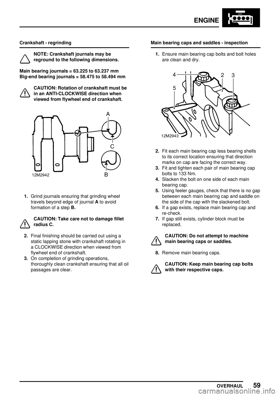
1.Grind journals ensuring that grinding wheel
travels beyond edge of journalAto avoid
formation of a stepB.
CAUTION: Take care not to damage fillet
radius C.
2.Final finishing should be carried out using a
static lapping stone with crankshaft rotating in
a CLOCKWISE direction when viewed from
flywheel end of crankshaft.
3.On completion of grinding operations,
thoroughly clean crankshaft ensuring that all oil
passages are clear.Main bearing caps and saddles - inspection
1.Ensure main bearing cap bolts and bolt holes
are clean and dry.
2.Fit each main bearing cap less bearing shells
to its correct location ensuring that direction
marks on cap are facing the correct way.
3.Fit and tighten each pair of main bearing cap
bolts to 133 Nm.
4.Slacken the bolt on one side of each main
bearing cap.
5.Using feeler gauges, check that there is no gap
between each main bearing cap and saddle on
the side of the cap with the slackened bolt.
6.If a gap exists, replace main bearing cap and
re-check.
7.If gap still exists, cylinder block must be
replaced.
CAUTION: Do not attempt to machine
main bearing caps or saddles.
8.Remove main bearing caps.
CAUTION: Keep main bearing cap bolts
with their respective caps.
Page 955 of 976
ENGINE
60
OVERHAUL Main bearing clearance - checking
CAUTION: If crankshaft has been
reground, oversize main bearing shells
must be fitted.
1.Degrease new main bearing shells and ensure
all traces of oil are removed from crankshaft
journals.
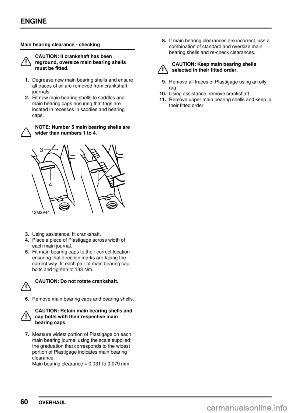
2.Fit new main bearing shells to saddles and
main bearing caps ensuring that tags are
located in recesses in saddles and bearing
caps.
NOTE: Number 5 main bearing shells are
wider than numbers 1 to 4.
3.Using assistance, fit crankshaft.
4.Place a piece of Plastigage across width of
each main journal.
5.Fit main bearing caps to their correct location
ensuring that direction marks are facing the
correct way; fit each pair of main bearing cap
bolts and tighten to 133 Nm.
CAUTION: Do not rotate crankshaft.
6.Remove main bearing caps and bearing shells.
CAUTION: Retain main bearing shells and
cap bolts with their respective main
bearing caps.
7.Measure widest portion of Plastigage on each
main bearing journal using the scale supplied;
the graduation that corresponds to the widest
portion of Plastigage indicates main bearing
clearance.
Main bearing clearance = 0.031 to 0.079 mm8.If main bearing clearances are incorrect, use a
combination of standard and oversize main
bearing shells and re-check clearances.
CAUTION: Keep main bearing shells
selected in their fitted order.
9.Remove all traces of Plastigage using an oily
rag.
10.Using assistance, remove crankshaft.
11.Remove upper main bearing shells and keep in
their fitted order.