Page 923 of 976

ENGINE
28
OVERHAUL 6.From all of the readings obtained, determine
highest protrusion figure and select the
appropriate cylinder head gasket.
Protrusion 0.50 to 0.60 mm - select gasket with
1 identification hole.
Protrusion 0.61 to 0.70 mm - select gasket with
2 identification holes.
Protrusion 0.71 to 0.80 mm - select gasket with
3 identification holes.
Protrusion 0.81 to 0.90 mm - select gasket with
0 identification holes.
NOTE: Identification holes are located on
the edge of the gasket.
7.Remove DTI.
8.Rotate crankshaft in a clockwise direction until
all pistons are half-way up cylinder bores.Cylinder head - refit
1.Ensure that mating faces of cylinder head and
block are clean and dry and that 2 locating
dowels are fitted in cylinder block.
2.Lubricate threads of new cylinder head bolts
with engine oil.
3.Check that cylinder head bolt holes in cylinder
block are clean and dry.
4.Rotate crankshaft in a clockwise direction until
pistons are half-way up cylinder bores.
5.Position the selected cylinder head gasket on
cylinder block ensuring that word "TOP" is
facing upwards.
6.Using assistance, fit cylinder head ensuring
that it is located on dowels.
Page 924 of 976
ENGINE
OVERHAUL29
7.Fit cylinder head bolts of the correct length in
positions shown.
CAUTION: Do not drop bolts into cylinder
block.
8.Tighten bolts until bolt heads just contact
cylinder head.
9.Using sequence shown, tighten cylinder head
bolts to 40 Nm.
Page 929 of 976
ENGINE
34
OVERHAUL Timing belt rear cover - refit
1.Remove all traces of gasket material from
cylinder block using suitable gasket removal
spray and a plastic scraper.
2.Screw 2 slave guide studs into cylinder block.
3.Fit new gasket over guide studs.
4.Note position of oil pump drive flats on
crankshaft.
5.Rotate oil pump inner rotor to align with drive
flats on crankshaft and position timing belt rear
cover on guide studs.
6.Fit timing belt rear cover.
CAUTION: Do not remove guide studs at
this stage.
7.Fit 8 bolts of the correct length in positions
shown, remove guide studs and fit remaining 2
bolts.
Page 931 of 976
ENGINE
36
OVERHAUL OIL FILTER HEAD
Remove
1.Remove and discard oil filter element.
2.Remove 4 bolts securing filter head to cylinder
block.
3.Remove filter head, remove and discard
gasket.Thermostatic valve - remove
1.Secure oil filter head in a soft-jawed vice with
thermostatic valve vertically upwards.
2.Remove 2 bolts securing thermostatic valve
extension housing to oil filter head.
3.Remove extension housing, remove and
discard 'O' ring.
4.Withdraw thermostatic valve and spring.
CAUTION: Do not separate valve from
spring.
Page 933 of 976
ENGINE
38
OVERHAUL Oil filter head - refit
1.Remove all traces of gasket from oil filter head
and cylinder block using suitable gasket
removal spray and a plastic scraper.
2.Smear a new gasket with engine oil and
position on oil filter head.
3.Fit oil filter head, fit 4 bolts and tighten to 45
Nm.
4.Smear sealing ring of new oil filter element with
engine oil and fit to oil filter head.
5.Plug open pipe connections to prevent ingress
of dirt.FUEL INJECTION PUMP
Remove
1.Remove timing belt.
2.Remove fuel pipes from pump and injectors.3.Ensure that timing pinLRT-12-045is inserted
in injection pump gear hub plate and injection
pump hub.
4.Remove 3 bolts securing hub and injection
pump gear to injection pump, remove timing
pinLRT-12-045and gear.
CAUTION: Do not remove nut securing
hub to pump.
Page 934 of 976
ENGINE
OVERHAUL39
5.Remove 3 bolts securing mounting bracket and
baffle plate to cylinder block.
6.Remove 2 bolts securing mounting bracket to
injection pump, remove bracket.
7.Remove banjo bolt securing fuel spill return
pipe to injection pump, discard sealing
washers.
CAUTION: Plug open connections to
prevent ingress of dirt.
8.Remove 3 nuts securing injection pump to
timing belt rear cover, remove injection pump.
Page 935 of 976

ENGINE
40
OVERHAUL Refit
1.Position injection pump to timing belt rear
cover, fit nuts and tighten to 25 Nm.
2.Fit fuel spill return pipe, fit banjo bolt and 2 new
sealing washers.
3.Tighten banjo bolt to 25 Nm.
4.Position mounting bracket to injection pump
and cylinder block, fit and finger tighten bolts.
5.Tighten mounting bracket bolts to 25 Nm in the
following order:
Mounting bracket to cylinder block
Mounting bracket to injection pump
6.Fit fuel pipes.
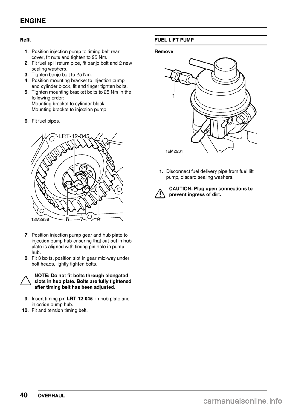
7.Position injection pump gear and hub plate to
injection pump hub ensuring that cut-out in hub
plate is aligned with timing pin hole in pump
hub.
8.Fit 3 bolts, position slot in gear mid-way under
bolt heads, lightly tighten bolts.
NOTE: Do not fit bolts through elongated
slots in hub plate. Bolts are fully tightened
after timing belt has been adjusted.
9.Insert timing pinLRT-12-045in hub plate and
injection pump hub.
10.Fit and tension timing belt.FUEL LIFT PUMP
Remove
1.Disconnect fuel delivery pipe from fuel lift
pump, discard sealing washers.
CAUTION: Plug open connections to
prevent ingress of dirt.
Page 936 of 976
ENGINE
OVERHAUL41
2.Remove 2 bolts securing fuel lift pump to
cylinder block, remove pump, gasket, spacer
and 2nd gasket.
3.Discard gaskets.Refit
1.Remove all traces of gasket using suitable
gasket removal spray and a plastic scraper.
2.Position new gaskets and spacer to fuel lift
pump.
3.Fit fuel lift pump ensuring that operating lever
is correctly positioned on camshaft.
4.Fit bolts and tighten to 25 Nm.
5.Position fuel delivery pipe to fuel lift pump, fit
banjo bolt and 2 new sealing washers.
CAUTION: Do not fully tighten banjo bolt
until pipe is connected to fuel filter.