Page 857 of 976
ELECTRICAL
37
REPAIR COOLANT TEMPERATURE AND FUEL GAUGES
Service repair no - 88.25.14 - Coolant temperature
gauge
Service repair no - 88.25.26 - Fuel gauge
Remove
1.Remove instrument cowl.
See Instrument
cowl and illumination board
2.Remove speedometer trip reset button sleeve.
3.Remove instrument face plate.
Coolant temperature gauge
4.Remove circuit board,See Circuit board
5.Remove 3 screws securing coolant temperature
gauge to binnacle, remove gauge.
Fuel gauge
6.Remove 3 screws securing fuel gauge to
binnacle, remove gauge.
Refit
7.Reverse removal procedure.SPEEDOMETER TRANSDUCER
Service repair no - 88.30.14
Remove
1.Position vehicle on ramp and chock wheels.
2.Raise ramp.
3.Disconnect multiplug from transducer.
4.Remove bolt securing transducer, remove
transducer.
Refit
5.Reverse removal procedure.
Page 861 of 976
ELECTRICAL
41
REPAIR COOLANT TEMPERATURE TRANSMITTER - V8i
Service repair no - 26.10.02
Remove
1.Disconnect battery negative lead.
2.Disconnect lead from transmitter.
3.Remove transmitter, discard sealing washer if
fitted.
Refit
4.Coat threads of replacement transmitter with
Loctite 572.
5.Fit a new sealing washer to transmitter.
6.Fit transmitter, connect lead.
7.Top-up cooling system.HEATED FRONT SCREEN
Heated front screen will operate when switch is
operated, with engine running. Timer unit will provide
a preset time cycle of 7« minutes±20%.
To identify timer unit.
See Electrical Trouble
Shooting Manual.Electrical Troubleshooting
Manual
Switching OFF ignition, or further operation of heated
front screen switch during cycle will switch off screen
and cancel, reset and switch off timer unit.
Page 886 of 976
ENGINE
DESCRIPTION AND OPERATION9
CYLINDER HEAD
1.Valve cap
2.Collets
3.Valve spring cup
4.Valve spring
5.Valve spring seat
6.Valve stem seal
7.Valve guide
8.Exhaust valve seat
9.Exhaust valve
10.Inlet valve seat
11.Inlet valve
12.Cylinder head bolt - M12 - long
13.Cylinder head bolt - M12 - short
14.Cylinder head bolt - M1015.Heater hose adaptor
16.Engine lifting brackets
17.Core plugs
18.Cylinder head gasket
19.Thermostat housing gasket
20.Coolant filler plug
21.Thermostat housing
22.Thermostat
23.Coolant outlet elbow
24.Coolant temperature sensor
25.Sealing washer
Page 913 of 976
ENGINE
18
OVERHAUL CYLINDER HEAD
Remove
1.Remove rocker shaft.
2.Remove fuel injectors.
3.Remove glow plugs.
4.Using sequence shown, progressively slacken
then remove and discard 18 bolts securing
cylinder head.
5.Using assistance, remove cylinder head.
NOTE: Dowel located.
6.Remove cylinder head gasket.
CAUTION: Identify cylinder head gasket
thickness by the number of holes in the
edge of the gasket between numbers 3
and 4 injector ports. Replacement gasket must
be of the same thickness as the original unless a
replacement cylinder head, crankshaft and/or
pistons are fitted.
- See Cylinder head gasket
selection.
7.Discard cylinder head gasket.
8.Remove 2 bolts securing coolant outlet elbow.
9.Remove coolant outlet elbow.
10.Remove thermostat from housing.
11.Remove 4 bolts securing thermostat housing to
cylinder head, remove housing.
12.Remove and discard gasket.
13.Remove all traces of gasket using suitable
gasket removal spray and a plastic scraper.
Page 925 of 976
ENGINE
30
OVERHAUL
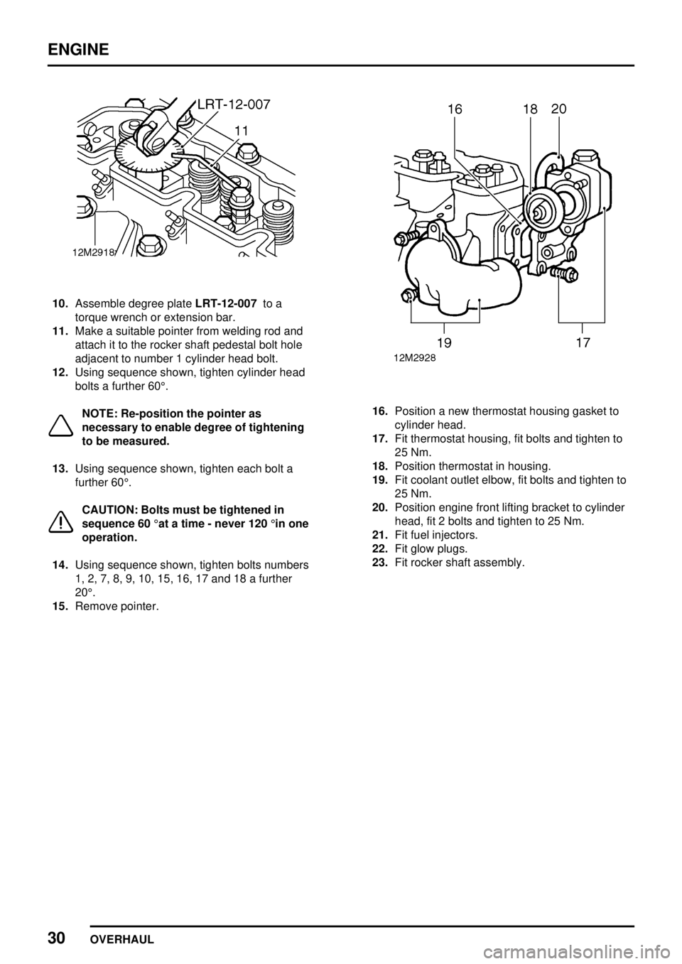
10.Assemble degree plateLRT-12-007to a
torque wrench or extension bar.
11.Make a suitable pointer from welding rod and
attach it to the rocker shaft pedestal bolt hole
adjacent to number 1 cylinder head bolt.
12.Using sequence shown, tighten cylinder head
bolts a further 60°.
NOTE: Re-position the pointer as
necessary to enable degree of tightening
to be measured.
13.Using sequence shown, tighten each bolt a
further 60°.
CAUTION: Bolts must be tightened in
sequence 60°at a time - never 120°in one
operation.
14.Using sequence shown, tighten bolts numbers
1, 2, 7, 8, 9, 10, 15, 16, 17 and 18 a further
20°.
15.Remove pointer.
16.Position a new thermostat housing gasket to
cylinder head.
17.Fit thermostat housing, fit bolts and tighten to
25 Nm.
18.Position thermostat in housing.
19.Fit coolant outlet elbow, fit bolts and tighten to
25 Nm.
20.Position engine front lifting bracket to cylinder
head, fit 2 bolts and tighten to 25 Nm.
21.Fit fuel injectors.
22.Fit glow plugs.
23.Fit rocker shaft assembly.
Page 975 of 976
ENGINE
DATA, TORQUE & TOOLS3
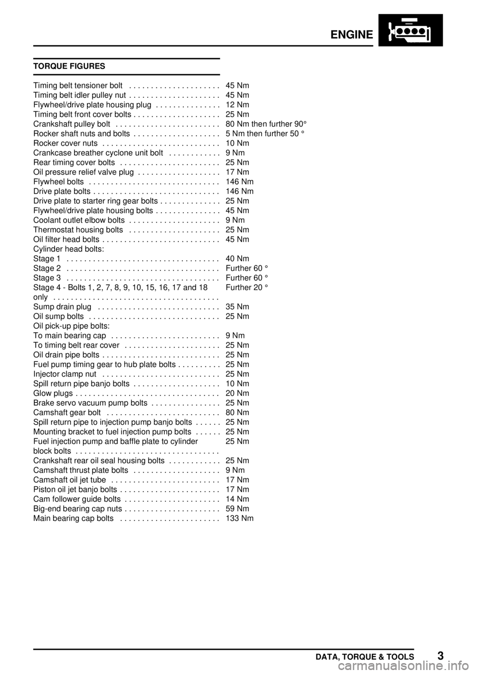
TORQUE FIGURES
Timing belt tensioner bolt 45 Nm.....................
Timing belt idler pulley nut 45 Nm.....................
Flywheel/drive plate housing plug 12 Nm...............
Timing belt front cover bolts 25 Nm....................
Crankshaft pulley bolt 80 Nm then further 90° ........................
Rocker shaft nuts and bolts 5 Nm then further 50° ....................
Rocker cover nuts 10 Nm...........................
Crankcase breather cyclone unit bolt 9 Nm............
Rear timing cover bolts 25 Nm.......................
Oil pressure relief valve plug 17 Nm...................
Flywheel bolts 146 Nm..............................
Drive plate bolts 146 Nm.............................
Drive plate to starter ring gear bolts 25 Nm..............
Flywheel/drive plate housing bolts 45 Nm...............
Coolant outlet elbow bolts 9 Nm.....................
Thermostat housing bolts 25 Nm.....................
Oil filter head bolts 45 Nm...........................
Cylinder head bolts:
Stage 1 40 Nm...................................
Stage 2 Further 60° ...................................
Stage 3 Further 60° ...................................
Stage 4 - Bolts 1, 2, 7, 8, 9, 10, 15, 16, 17 and 18
onlyFurther 20°
......................................
Sump drain plug 35 Nm............................
Oil sump bolts 25 Nm..............................
Oil pick-up pipe bolts:
To main bearing cap 9 Nm.........................
To timing belt rear cover 25 Nm......................
Oil drain pipe bolts 25 Nm...........................
Fuel pump timing gear to hub plate bolts 25 Nm..........
Injector clamp nut 25 Nm...........................
Spill return pipe banjo bolts 10 Nm....................
Glow plugs 20 Nm.................................
Brake servo vacuum pump bolts 25 Nm................
Camshaft gear bolt 80 Nm..........................
Spill return pipe to injection pump banjo bolts 25 Nm......
Mounting bracket to fuel injection pump bolts 25 Nm......
Fuel injection pump and baffle plate to cylinder
block bolts25 Nm
.................................
Crankshaft rear oil seal housing bolts 25 Nm............
Camshaft thrust plate bolts 9 Nm....................
Camshaft oil jet tube 17 Nm.........................
Piston oil jet banjo bolts 17 Nm.......................
Cam follower guide bolts 14 Nm......................
Big-end bearing cap nuts 59 Nm......................
Main bearing cap bolts 133 Nm.......................


