1995 JEEP YJ shifter
[x] Cancel search: shifterPage 216 of 2158
(8) Remove shift handle by pulling upward sharply
on handle. Then remove shift bezel (Fig. 7).
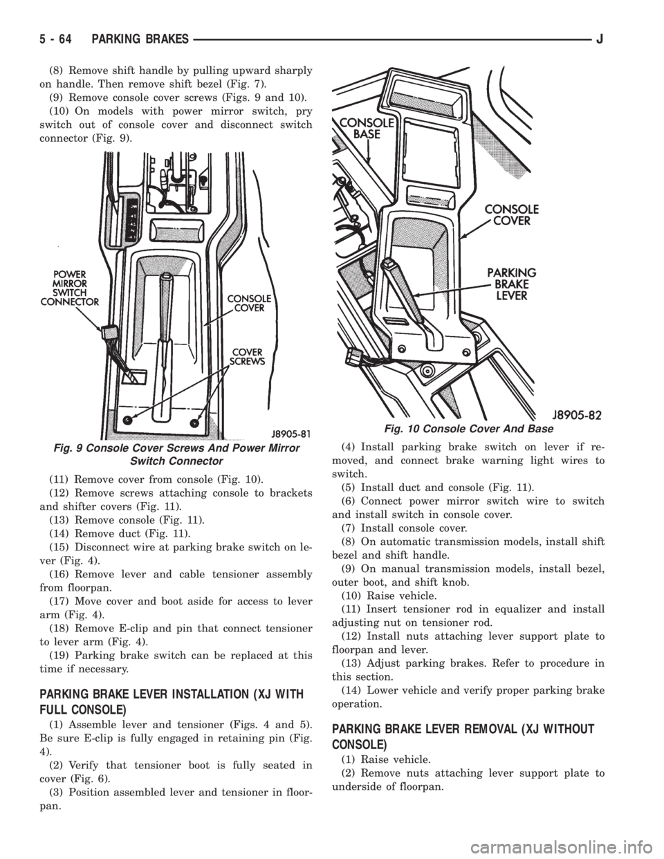
(9) Remove console cover screws (Figs. 9 and 10).
(10) On models with power mirror switch, pry
switch out of console cover and disconnect switch
connector (Fig. 9).
(11) Remove cover from console (Fig. 10).
(12) Remove screws attaching console to brackets
and shifter covers (Fig. 11).
(13) Remove console (Fig. 11).
(14) Remove duct (Fig. 11).
(15) Disconnect wire at parking brake switch on le-
ver (Fig. 4).
(16) Remove lever and cable tensioner assembly
from floorpan.
(17) Move cover and boot aside for access to lever
arm (Fig. 4).
(18) Remove E-clip and pin that connect tensioner
to lever arm (Fig. 4).
(19) Parking brake switch can be replaced at this
time if necessary.
PARKING BRAKE LEVER INSTALLATION (XJ WITH
FULL CONSOLE)
(1) Assemble lever and tensioner (Figs. 4 and 5).
Be sure E-clip is fully engaged in retaining pin (Fig.
4).
(2) Verify that tensioner boot is fully seated in
cover (Fig. 6).
(3) Position assembled lever and tensioner in floor-
pan.(4) Install parking brake switch on lever if re-
moved, and connect brake warning light wires to
switch.
(5) Install duct and console (Fig. 11).
(6) Connect power mirror switch wire to switch
and install switch in console cover.
(7) Install console cover.
(8) On automatic transmission models, install shift
bezel and shift handle.
(9) On manual transmission models, install bezel,
outer boot, and shift knob.
(10) Raise vehicle.
(11) Insert tensioner rod in equalizer and install
adjusting nut on tensioner rod.
(12) Install nuts attaching lever support plate to
floorpan and lever.
(13) Adjust parking brakes. Refer to procedure in
this section.
(14) Lower vehicle and verify proper parking brake
operation.PARKING BRAKE LEVER REMOVAL (XJ WITHOUT
CONSOLE)
(1) Raise vehicle.
(2) Remove nuts attaching lever support plate to
underside of floorpan.
Fig. 9 Console Cover Screws And Power Mirror
Switch Connector
Fig. 10 Console Cover And Base
5 - 64 PARKING BRAKESJ
Page 351 of 2158
INSTALLATION
(1) Connect electrical connectors to ignition switch.
Make sure that switch locking tabs are fully seated
in wiring connectors.
(2) Before attaching ignition switch to a tilt steer-
ing column, the transmission shifter must be in Park
position. The park lock dowel pin and column lock
flag must also be properly indexed before installing
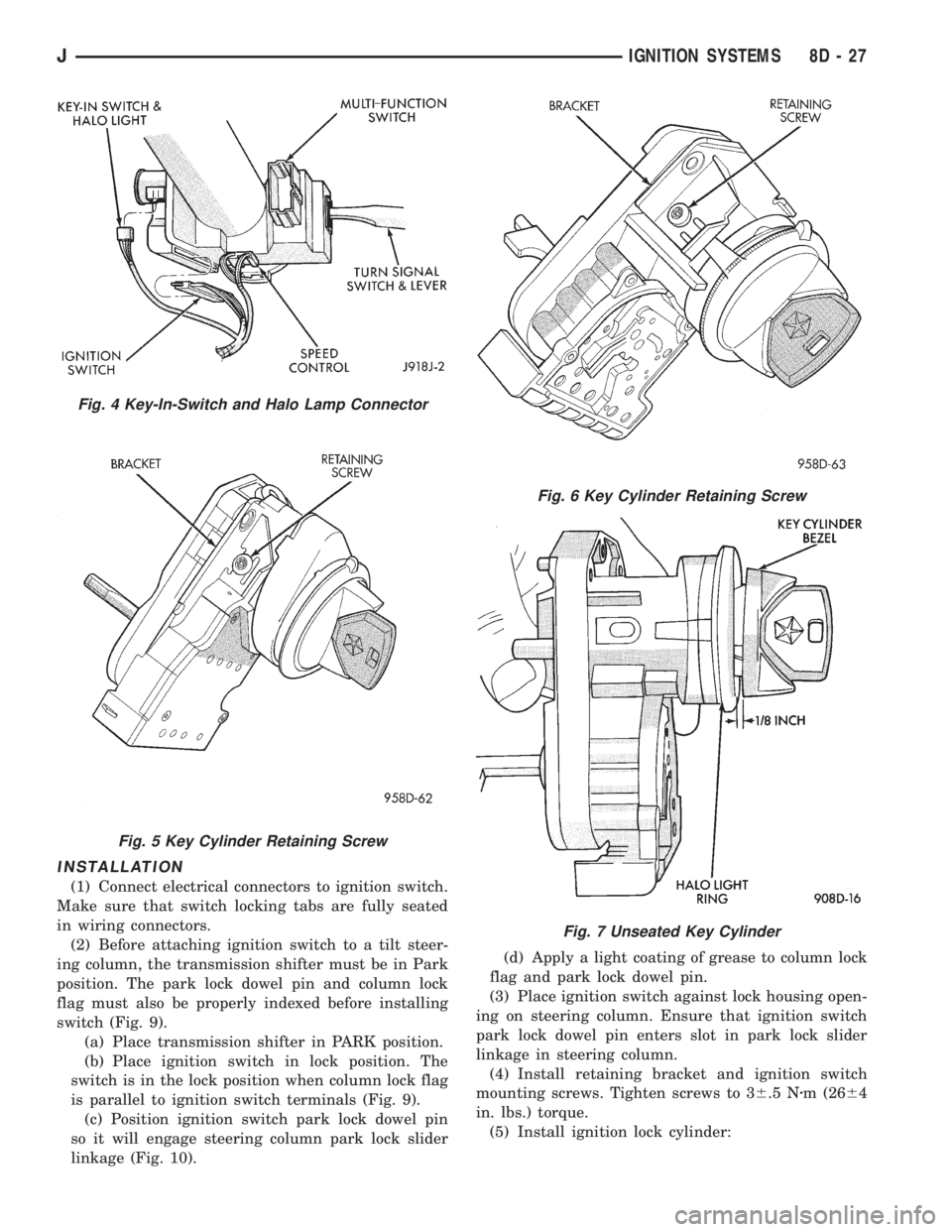
switch (Fig. 9).
(a) Place transmission shifter in PARK position.
(b) Place ignition switch in lock position. The
switch is in the lock position when column lock flag
is parallel to ignition switch terminals (Fig. 9).
(c) Position ignition switch park lock dowel pin
so it will engage steering column park lock slider
linkage (Fig. 10).(d) Apply a light coating of grease to column lock
flag and park lock dowel pin.
(3) Place ignition switch against lock housing open-
ing on steering column. Ensure that ignition switch
park lock dowel pin enters slot in park lock slider
linkage in steering column.
(4) Install retaining bracket and ignition switch
mounting screws. Tighten screws to 36.5 Nzm (2664
in. lbs.) torque.
(5) Install ignition lock cylinder:
Fig. 4 Key-In-Switch and Halo Lamp Connector
Fig. 5 Key Cylinder Retaining Screw
Fig. 6 Key Cylinder Retaining Screw
Fig. 7 Unseated Key Cylinder
JIGNITION SYSTEMS 8D - 27
Page 1425 of 2158
The engine will not operate if the PCM does not re-
ceive a crankshaft position sensor input.
ENGINE COOLANT TEMPERATURE SENSORÐPCM
INPUT
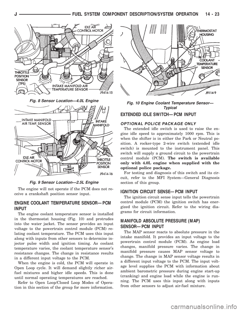
The engine coolant temperature sensor is installed
in the thermostat housing (Fig. 10) and protrudes
into the water jacket. The sensor provides an input
voltage to the powertrain control module (PCM) re-
lating coolant temperature. The PCM uses this input
along with inputs from other sensors to determine in-
jector pulse width and ignition timing. As coolant
temperature varies, the coolant temperature sensor's
resistance changes. The change in resistance results
in a different input voltage to the PCM.
When the engine is cold, the PCM will operate in
Open Loop cycle. It will demand slightly richer air-
fuel mixtures and higher idle speeds. This is done
until normal operating temperatures are reached.
Refer to Open Loop/Closed Loop Modes of Opera-
tion in this section of the group for more information.
EXTENDED IDLE SWITCHÐPCM INPUT
OPTIONAL POLICE PACKAGE ONLY
The extended idle switch is used to raise the en-
gine idle speed to approximately 1000 rpm. This is
when the shifter is in either the Park or Neutral po-
sition. A rocker-type 2-wire switch (extended idle
switch) is mounted to the instrument panel. This
switch will supply a ground circuit to the powertrain
control module (PCM).The switch is available
only with 4.0L engine when supplied with the
optional police package.
For testing and diagnosis of this switch and its cir-
cuit, refer to the MFI SystemÐGeneral Diagnosis
section of this group.
IGNITION CIRCUIT SENSEÐPCM INPUT
The ignition circuit sense input tells the powertrain
control module (PCM) the ignition switch has ener-
gized the ignition circuit. Refer to the wiring dia-
grams for circuit information.
MANIFOLD ABSOLUTE PRESSURE (MAP)
SENSORÐPCM INPUT
The MAP sensor reacts to absolute pressure in the
intake manifold. It provides an input voltage to the
powertrain control module (PCM). As engine load
changes, manifold pressure varies. The change in
manifold pressure causes MAP sensor voltage to
change. The change in MAP sensor voltage results in
a different input voltage to the PCM. The input volt-
age level supplies the PCM with information about
ambient barometric pressure during engine start-up
(cranking) and engine load while the engine is run-
ning. The PCM uses this input along with inputs
from other sensors to adjust air-fuel mixture.
Fig. 8 Sensor LocationÐ4.0L Engine
Fig. 9 Sensor LocationÐ2.5L Engine
Fig. 10 Engine Coolant Temperature SensorÐ
Typical
JFUEL SYSTEM COMPONENT DESCRIPTION/SYSTEM OPERATION 14 - 23
Page 1434 of 2158
²The PCM adjusts ignition timing by increasing
and decreasing spark advance.
²The PCM operates the A/C compressor clutch
through the clutch relay. This happens if A/C has
been selected by the vehicle operator and requested
by the A/C thermostat.
The optional Extended Idle Switch is used to raise
the engine idle speed to approximately 1000 rpm.
This is when the shifter is in either the Park or Neu-
tral position. A rocker-type 2-wire switch (extended
idle switch) is mounted to the instrument panel. This
switch will supply a ground circuit to the powertrain
control module (PCM).The switch is available
only with 4.0L engine when supplied with the
optional police package.
CRUISE MODE
When the engine is at operating temperature, this
is a Closed Loop mode. At cruising speed, the power-
train control module (PCM) receives inputs from:
²Air conditioning select signal (if equipped)
²Air conditioning request signal (if equipped)
²Battery voltage
²Engine coolant temperature sensor
²Crankshaft position sensor
²Intake manifold air temperature sensor
²Manifold absolute pressure (MAP) sensor
²Throttle position sensor (TPS)
²Camshaft position sensor signal (in the distribu-
tor)
²Park/neutral switch (gear indicator signalÐauto.
trans. only)
²Oxygen (O2S) sensor
Based on these inputs, the following occurs:
²Voltage is applied to the fuel injectors with the
PCM. The PCM will then adjust the injector pulse
width by turning the ground circuit to each individ-
ual injector on and off.
²The PCM monitors the O2S sensor input and ad-
justs air-fuel ratio. It also adjusts engine idle speed
through the idle air control (IAC) motor.
²The PCM adjusts ignition timing by turning the
ground path to the coil on and off.
²The PCM operates the A/C compressor clutch
through the clutch relay. This happens if A/C has
been selected by the vehicle operator and requested
by the A/C thermostat.
ACCELERATION MODE
This is an Open Loop mode. The powertrain control
module (PCM) recognizes an abrupt increase in
throttle position or MAP pressure as a demand for
increased engine output and vehicle acceleration. The
PCM increases injector pulse width in response to in-
creased throttle opening.
DECELERATION MODE
When the engine is at operating temperature, this
is an Open Loop mode. During hard deceleration, the
powertrain control module (PCM) receives the follow-
ing inputs.
²Air conditioning select signal (if equipped)
²Air conditioning request signal (if equipped)
²Battery voltage
²Engine coolant temperature sensor
²Crankshaft position sensor
²Intake manifold air temperature sensor
²Manifold absolute pressure (MAP) sensor
²Throttle position sensor (TPS)
²Camshaft position sensor signal (in the distribu-
tor)
²Park/neutral switch (gear indicator signalÐauto.
trans. only)
If the vehicle is under hard deceleration with the
proper rpm and closed throttle conditions, the PCM
will ignore the oxygen sensor input signal. The PCM
will enter a fuel cut-off strategy in which it will not
supply battery voltage to the injectors. If a hard de-
celeration does not exist, the PCM will determine the
proper injector pulse width and continue injection.
Based on the above inputs, the PCM will adjust en-
gine idle speed through the idle air control (IAC) mo-
tor.
The PCM adjusts ignition timing by turning the
ground path to the coil on and off.
The PCM opens the ground circuit to the A/C
clutch relay to disengage the A/C compressor clutch.
This is done until the vehicle is no longer under de-
celeration (if the A/C system is operating).
WIDE OPEN THROTTLE MODE
This is an Open Loop mode. During wide open
throttle operation, the powertrain control module
(PCM) receives the following inputs.
²Battery voltage
²Crankshaft position sensor
²Engine coolant temperature sensor
²Intake manifold air temperature sensor
²Manifold absolute pressure (MAP) sensor
²Throttle position sensor (TPS)
²Camshaft position sensor signal (in the distribu-
tor)
During wide open throttle conditions, the following
occurs:
²Voltage is applied to the fuel injectors with the
powertrain control module (PCM). The PCM will
then control the injection sequence and injector pulse
width by turning the ground circuit to each individ-
ual injector on and off. The PCM ignores the oxygen
sensor input signal and provides a predetermined
amount of additional fuel. This is done by adjusting
injector pulse width.
²The PCM adjusts ignition timing by turning the
ground path to the coil on and off.
14 - 32 FUEL SYSTEM COMPONENT DESCRIPTION/SYSTEM OPERATIONJ
Page 1450 of 2158
EXTENDED IDLE SWITCH TEST
OPTIONAL POLICE PACKAGE ONLY
OPERATION
The extended idle switch is used to raise the en-
gine idle speed to approximately 1000 rpm when the
shifter is in either the Park or Neutral position. A
rocker-type 2-wire switch (extended idle switch) is
mounted to the instrument panel.This switch is
available only with 4.0L engine when supplied
with the optional police package.
TESTING
The extended idle switch will control a ground cir-
cuit going to the powertrain control module (PCM).
When a ground signal (through this switch) has been
received at pin number 10 in the PCM, engine idle
speed will increase.
Bring the engine to normal operating temperature
and turn the extended idle switch to the ON position.
Engine speed should now increase to approximately
1000 rpm when the shifter is in either the Park or
Neutral position. If engine speed does not increase,
apply a good ground to pin number 10 at the PCM
using a small paper clip. Be careful not to damage
the wiring with the paper clip. If the engine speed
now increases, it can be assumed that the PCM is
functioning correctly. Check the instrument panel
mounted switch for a closed ground circuit when in
the ON position. If the engine speed will not increase
after applying a ground to pin number 10, replace
the PCM. Refer to Group 8W, Wiring Diagrams for
circuit and wiring information.
THROTTLE POSITION SENSOR (TPS) TEST
To perform a complete test of the sensor and its cir-
cuitry, refer to DRB scan tool and appropriate Pow-
ertrain Diagnostics Procedures manual. To test the
sensor only, refer to the following:
The throttle position sensor (TPS) can be tested
with a digital voltmeter. The center terminal of the
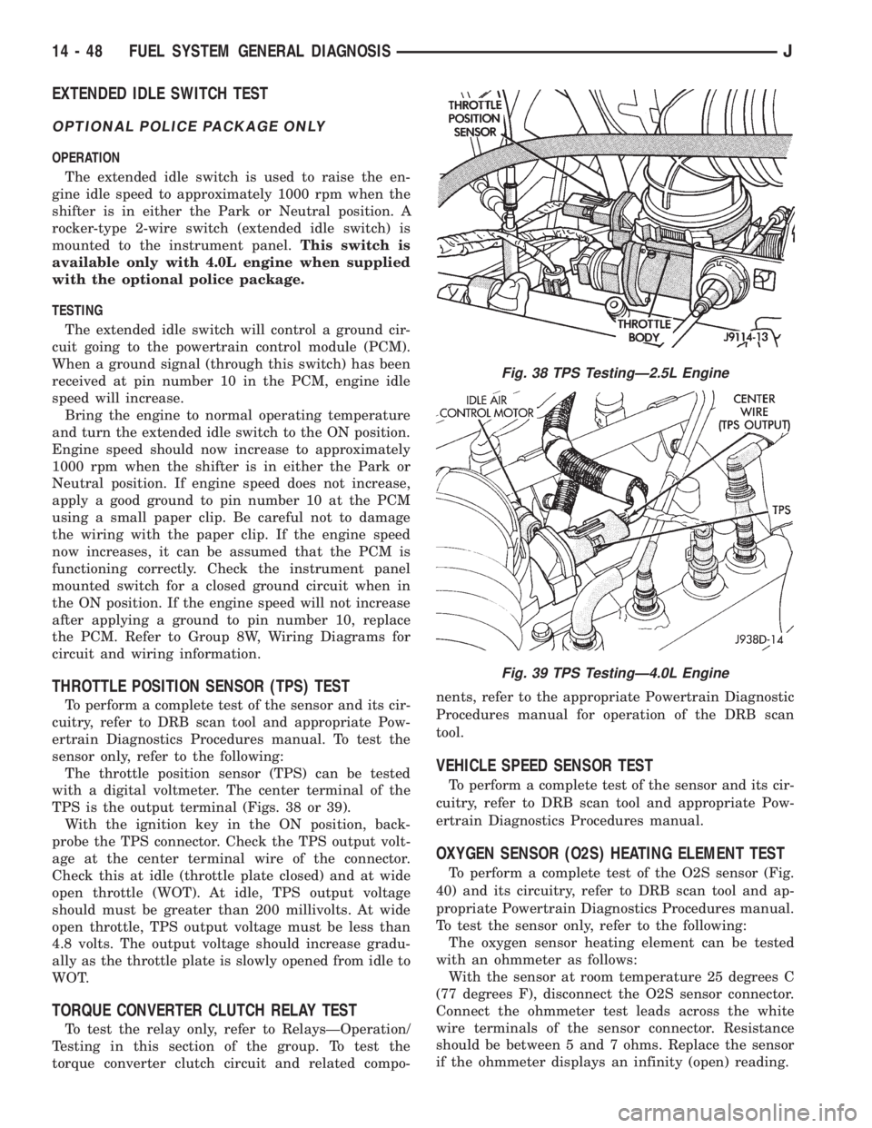
TPS is the output terminal (Figs. 38 or 39).
With the ignition key in the ON position, back-
probe the TPS connector. Check the TPS output volt-
age at the center terminal wire of the connector.
Check this at idle (throttle plate closed) and at wide
open throttle (WOT). At idle, TPS output voltage
should must be greater than 200 millivolts. At wide
open throttle, TPS output voltage must be less than
4.8 volts. The output voltage should increase gradu-
ally as the throttle plate is slowly opened from idle to
WOT.
TORQUE CONVERTER CLUTCH RELAY TEST
To test the relay only, refer to RelaysÐOperation/
Testing in this section of the group. To test the
torque converter clutch circuit and related compo-nents, refer to the appropriate Powertrain Diagnostic
Procedures manual for operation of the DRB scan
tool.
VEHICLE SPEED SENSOR TEST
To perform a complete test of the sensor and its cir-
cuitry, refer to DRB scan tool and appropriate Pow-
ertrain Diagnostics Procedures manual.
OXYGEN SENSOR (O2S) HEATING ELEMENT TEST
To perform a complete test of the O2S sensor (Fig.
40) and its circuitry, refer to DRB scan tool and ap-
propriate Powertrain Diagnostics Procedures manual.
To test the sensor only, refer to the following:
The oxygen sensor heating element can be tested
with an ohmmeter as follows:
With the sensor at room temperature 25 degrees C
(77 degrees F), disconnect the O2S sensor connector.
Connect the ohmmeter test leads across the white
wire terminals of the sensor connector. Resistance
should be between 5 and 7 ohms. Replace the sensor
if the ohmmeter displays an infinity (open) reading.
Fig. 38 TPS TestingÐ2.5L Engine
Fig. 39 TPS TestingÐ4.0L Engine
14 - 48 FUEL SYSTEM GENERAL DIAGNOSISJ
Page 1537 of 2158
(14) Remove the Interlock cable from the steering
column. Refer to Automatic Transmission Shifter/Ig-
nition Interlock in this group.
(15) Remove the column. Use care to avoid damag-
ing the paint or trim.
INSTALLATION
CAUTION: Bumping, jolting and hammering on the
steering column shaft and gear shift tube must be
avoided during all service procedures.
(1) With the front wheels in the straight ahead po-
sition. Align and install the column to coupler.Do
not apply force at the top of the steering col-
umn shaft.(2) Ensure the ground clip is on the left spacer slot
(Fig. 17).
(3) Install the Interlock cable from the steering col-
umn. Refer to Automatic Transmission Shifter/Igni-
tion Interlock in this group.
(4) Install wiring harness connections to steering
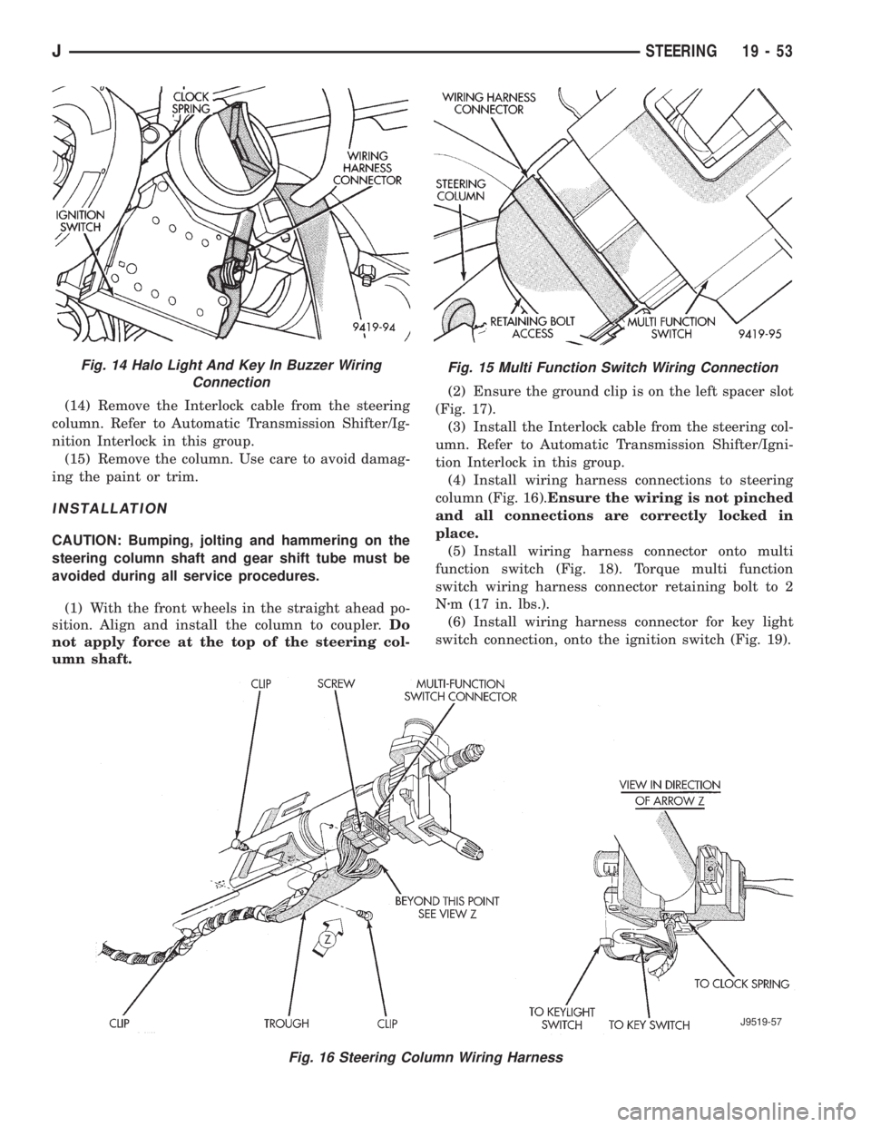
column (Fig. 16).Ensure the wiring is not pinched
and all connections are correctly locked in
place.
(5) Install wiring harness connector onto multi
function switch (Fig. 18). Torque multi function
switch wiring harness connector retaining bolt to 2
Nzm (17 in. lbs.).
(6) Install wiring harness connector for key light
switch connection, onto the ignition switch (Fig. 19).
Fig. 15 Multi Function Switch Wiring Connection
Fig. 16 Steering Column Wiring Harness
J9519-57
Fig. 14 Halo Light And Key In Buzzer Wiring
Connection
JSTEERING 19 - 53
Page 1539 of 2158
(1) Remove the ignition switch from the steering
column. Refer toGroup 8D Ignition System.
(2) Using a key cylinder, check the turning effort of
the switch.
²If the ignition switch binds look for the following
conditions.
(1) Look for rough areas or flash in the casting and
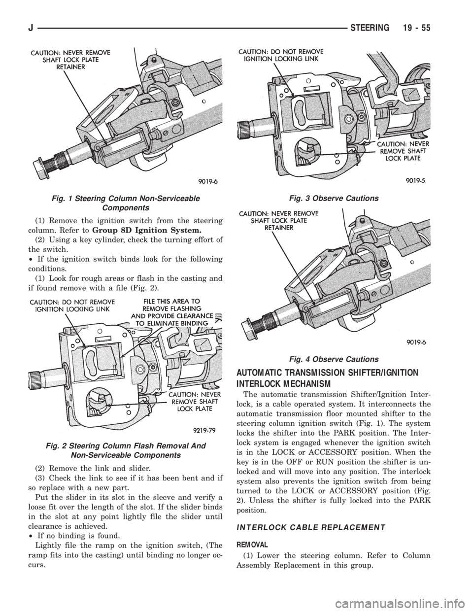
if found remove with a file (Fig. 2).
(2) Remove the link and slider.
(3) Check the link to see if it has been bent and if
so replace with a new part.
Put the slider in its slot in the sleeve and verify a
loose fit over the length of the slot. If the slider binds
in the slot at any point lightly file the slider until
clearance is achieved.
²If no binding is found.
Lightly file the ramp on the ignition switch, (The
ramp fits into the casting) until binding no longer oc-
curs.
AUTOMATIC TRANSMISSION SHIFTER/IGNITION
INTERLOCK MECHANISM
The automatic transmission Shifter/Ignition Inter-
lock, is a cable operated system. It interconnects the
automatic transmission floor mounted shifter to the
steering column ignition switch (Fig. 1). The system
locks the shifter into the PARK position. The Inter-
lock system is engaged whenever the ignition switch
is in the LOCK or ACCESSORY position. When the
key is in the OFF or RUN position the shifter is un-
locked and will move into any position. The interlock
system also prevents the ignition switch from being
turned to the LOCK or ACCESSORY position (Fig.
2). Unless the shifter is fully locked into the PARK
position.
INTERLOCK CABLE REPLACEMENT
REMOVAL
(1) Lower the steering column. Refer to Column
Assembly Replacement in this group.
Fig. 1 Steering Column Non-Serviceable
Components
Fig. 2 Steering Column Flash Removal And
Non-Serviceable Components
Fig. 3 Observe Cautions
Fig. 4 Observe Cautions
JSTEERING 19 - 55
Page 1541 of 2158
(3) Place the ignition key cylinder in the ACCES-
SORY position.
(4) Remove shipping pin from plastic base.
(5) Connect the cable eyelet to the bellcrank pin
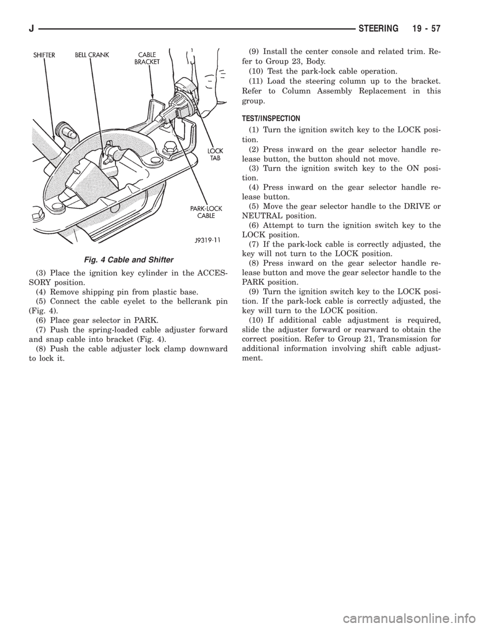
(Fig. 4).
(6) Place gear selector in PARK.
(7) Push the spring-loaded cable adjuster forward
and snap cable into bracket (Fig. 4).
(8) Push the cable adjuster lock clamp downward
to lock it.(9) Install the center console and related trim. Re-
fer to Group 23, Body.
(10) Test the park-lock cable operation.
(11) Load the steering column up to the bracket.
Refer to Column Assembly Replacement in this
group.
TEST/INSPECTION
(1) Turn the ignition switch key to the LOCK posi-
tion.
(2) Press inward on the gear selector handle re-
lease button, the button should not move.
(3) Turn the ignition switch key to the ON posi-
tion.
(4) Press inward on the gear selector handle re-
lease button.
(5) Move the gear selector handle to the DRIVE or
NEUTRAL position.
(6) Attempt to turn the ignition switch key to the
LOCK position.
(7) If the park-lock cable is correctly adjusted, the
key will not turn to the LOCK position.
(8) Press inward on the gear selector handle re-
lease button and move the gear selector handle to the
PARK position.
(9) Turn the ignition switch key to the LOCK posi-
tion. If the park-lock cable is correctly adjusted, the
key will turn to the LOCK position.
(10) If additional cable adjustment is required,
slide the adjuster forward or rearward to obtain the
correct position. Refer to Group 21, Transmission for
additional information involving shift cable adjust-
ment.
Fig. 4 Cable and Shifter
JSTEERING 19 - 57