1995 JEEP YJ wiring
[x] Cancel search: wiringPage 445 of 2158
The liftgate wiper motor can not be repaired. If
faulty, the entire assembly must be replaced.
WINDSHIELD WIPER/WASHER SWITCH
Controls for the windshield wiper and washer sys-
tems are contained in the turn signal switch lever.
The turn signal switch lever is mounted on the left
side of the steering column between the steering
wheel and the instrument panel. The wiper/washer
switch can not be repaired. If any function of the
switch is faulty, the entire switch must be replaced.
LIFTGATE WIPER/WASHER SWITCH
The single two-function switch on the instrument
panel right of the steering column controls the lift-
gate wiper and washer functions. The rocker-type
switch features a detent in the WIPE position, but
only momentary contact in the WASH position. Both
the liftgate wiper and liftgate washer motors will op-
erate continuously for as long as the switch is held in
the WASH position. The switch can not be repaired;
if faulty, it must be replaced.
INTERMITTENT WIPE MODULE
In addition to low and high speed, the optional in-
termittent wipe system has a delay mode. The delay
mode has a range of 2 to 15 seconds. The length of
the delay is selected with a variable resistor in the
wiper switch and is accomplished by electronic cir-
cuitry within the intermittent wipe module. If the
washer knob is depressed while the wiper switch is
in the OFF position, the intermittent wipe module
will operate the wiper motor for approximately 2
wipes and automatically turn the motor off.
The intermittent wipe module is mounted to a
bracket behind the lower instrument panel, near the
steering column with a hook and loop fastener patch.
The module can not be repaired.
WINDSHIELD WASHER NOZZLES
The two fluidic washer nozzles are screwed into
openings in the cowl panel below the windshield and
are not adjustable. Washer fluid is fed to the nozzles
through hoses underneath the cowl panel. The noz-
zles can not be repaired and, if faulty, should be re-
placed.
LIFTGATE WASHER NOZZLE
The single liftgate washer nozzle is installed
through the liftgate glass and secured with a nut on
the inside of the glass. Washer fluid is fed to the noz-
zle from the washer reservoir in the engine compart-
ment. A liftgate washer hose system is routed
through the body of the vehicle with the body wiring
harness from the reservoir to the liftgate. The nozzle
can not be repaired and, if faulty, should be replaced.
WASHER RESERVOIR
The washer solvent reservoir is mounted with a
bracket to the left front inner fender shield near the
cowl panel. The same reservoir is used for both the
standard front and optional liftgate washer systems.
The reservoir and filler cap are available for service.
WASHER PUMPS
The washer pump and motor are press-fit into a
rubber grommet near the bottom of the washer res-
ervoir. Vehicles with the optional liftgate wiper/
washer system have two pumps installed in the
single reservoir. A permanently lubricated and sealed
motor is coupled to a rotor-type pump. Washer fluid
is gravity fed from the reservoir to the pump. The
pump then pressurizes the fluid and forces it through
the plumbing to the nozzles when the motor is ener-
gized. The pump and motor can not be repaired. If
faulty, the entire assembly must be replaced.
JWIPER AND WASHER SYSTEMS - YJ 8K - 11
Page 446 of 2158
DIAGNOSIS - YJ
WINDSHIELD WIPER SYSTEM
(1) Remove circuit breaker from fuseblock module
and turn ignition switch to ACCESSORY or ON.
(a) Measure voltage at battery side of circuit
breaker cavity. Meter should read battery voltage.
If not OK, repair wiring from ignition switch.
(b) Measure resistance across circuit breaker ter-
minals. Meter should read zero ohms. If not OK,
replace failed circuit breaker.
(2) Unplug wiper motor side of wiring harness con-
nector (gray) from wiper switch side of wiring har-
ness connector (black), or from intermittent wipe
module (if equipped) at base of steering column. Turn
ignition switch to ACCESSORY or ON.
(a) Measure voltage at unplugged wiper motor
side of wiring harness connector (gray) terminal D.
Meter should read battery voltage. If not OK, re-
pair wiring from circuit breaker.
(b) Turn ignition switch to OFF and measure re-
sistance from unplugged wiper motor side of wiring
harness connector (gray) terminal G to ground.
Meter should read zero ohms. If not OK, repair
wiring to ground.
(3) Leave ignition switch in OFF, and back probe
wiring harness connector at wiper motor. Measure re-
sistance from terminal E of wiper motor side of con-
nector to ground. Meter should read zero ohms. If not
OK, repair wiring to ground.
(4) If equipped with intermittent wipe, turn igni-
tion switch to ACCESSORY or ON. Turn wiper
switch to LOW or HIGH. Unplug wiper switch side of
wiring harness connector (black) from intermittent
wipe module. Then plug both connectors that have
been removed from intermittent wipe module into
each other.
CAUTION: DO NOT move the wiper switch to DE-
LAY with the intermittent wipe module removed
from the circuit. If the switch is moved to the DE-
LAY position during the next step, the switch will be
damaged.
Test wiper operation in LOW and HIGH speed
modes, and test washer operation. If these modes
were inoperative, but are OK now, replace failed in-
termittent wipe module.
(5) To test the wiper/washer switch, see Windshield
Wiper/Washer Switch Testing. Turn ignition switch to
OFF. Position the wiper switch as indicated, and
back probe wiper switch side of wiring harness con-
nector (black). If switch tests OK, go to step 6. If not
OK, replace switch and go to step 7.
(6) To further test the wiper/washer switch, turn
ignition switch to ACCESSORY or ON. Position thewiper switch as indicated in the tests below, and
back probe wiper switch side of wiring harness con-
nector (black).
(a) Measure voltage at connector terminal E with
wiper switch in LOW, MIST and with washer
switch depressed. Meter should read battery volt-
age. If not OK, replace switch.
(b) Measure voltage at connector terminal C with
wiper switch in HIGH. Meter should read battery
voltage. If not OK, replace switch.
(c) With wiper switch in LOW or HIGH, measure
voltage at connector terminal F, then move wiper
switch to OFF. Meter should read battery voltage
until wipers park and then zero volts. If OK, go to
step 7. If not OK, check wiring to wiper motor, then
go to step 8.
(7) To test the wiper motor, turn the ignition
switch to ACCESSORY or ON. Position the wiper
switch and back probe the motor connector as indi-
cated.
(a) Wiper switch in any position, measure volt-
age at terminal B. Meter should read battery volt-
age. If not OK, repair wiring from circuit breaker.
(b) Wiper switch in LOW, measure voltage at ter-
minal A. Meter should read battery voltage. If OK,
but wipers do not operate, replace failed wiper mo-
tor. If not OK, repair wiring from switch or inter-
mittent wipe module connector.
(c) Wiper switch in HIGH, measure voltage at
terminal H. Meter should read battery voltage. If
OK, but wipers do not operate, replace failed wiper
motor. If not OK, repair wiring from switch or in-
termittent wipe module connector.
(d) Wiper switch in LOW or HIGH, voltmeter
connected to terminal D. Turn wiper switch to OFF
and observe meter. Meter should read battery volt-
age when switch goes to OFF, then zero volts after
wipers park. If battery voltage is present, but wip-
ers fail to park; or, if no battery voltage present, re-
place failed wiper motor.
WINDSHIELD WASHER SYSTEM
WITH NON-INTERMITTENT WIPE
(1) Measure resistance from washer pump connec-
tor terminal B to a clean chassis ground. Meter
should read zero ohms. If not OK, repair open be-
tween terminal B and ground.
(2) Turn ignition switch to ON and press washer
switch.
(a) Measure voltage at switch connector terminal
B. Meter should read battery voltage. If not OK, re-
place wiper/washer switch.
(b) Measure voltage at washer pump connector
terminal A. Meter should read battery voltage. If
8K - 12 WIPER AND WASHER SYSTEMS - YJJ
Page 450 of 2158

LIFTGATE WIPER/WASHER SYSTEM
(1) Turn ignition switch to ON and liftgate wiper/
washer switch to WASH.
(a) Measure voltage at switch connector terminal
P. Meter should read battery voltage. If not OK,
check fuse 1.
(b) Measure voltage at switch connector terminal
B. Meter should read battery voltage. If not OK, re-
place switch.
(c) Measure voltage at switch connector terminal
A. Meter should read battery voltage. If not OK, re-
place switch.
(2) Unplug liftgate washer pump connector.
(a) With ignition switch in OFF position, mea-
sure resistance at pump connector black wire to
ground. Meter should read zero ohms. If not OK,
repair open to ground.
(b) With ignition switch in ON position, measure
voltage at pump connector brown/white wire,
switch in WASH. Meter should read battery volt-
age. If OK, replace pump. If not OK, check wiring.
(3) Turn ignition switch to ON, unplug liftgate
wiper motor connector and place wiper switch in
WIPE.
(a) Measure resistance at motor connector termi-
nal B to ground. Meter should read zero ohms. If
not OK, repair open to ground.
(b) Measure voltage at motor connector terminal
A. Meter should read battery voltage. If not OK,
check wiring to fuse.
(c) Measure voltage at motor connector terminal
C. Meter should read battery voltage. If OK, re-
place motor. If not OK, repair open to switch.
LIFTGATE WIPER/WASHER SWITCH
See Liftgate Wiper/Washer Switch Diagram (Fig. 1)
and Liftgate Wiper Switch Tests (Fig. 2). Check
switch continuity and resistance accordingly. If
switch fails any test, replace faulty switch.
Fig. 1 Liftgate Wiper/Washer Switch Diagram
Fig. 2 Liftgate Wiper/Washer Switch Tests
8K - 16 WIPER AND WASHER SYSTEMS - YJJ
Page 452 of 2158
(2) Remove the nuts attaching the pivots to the
windshield frame.
(3) Remove the necessary hard or soft top compo-
nents from the windshield frame.
(4) Remove the windshield holddown bolts in the
lower corners of the instrument panel and fold the
windshield forward.
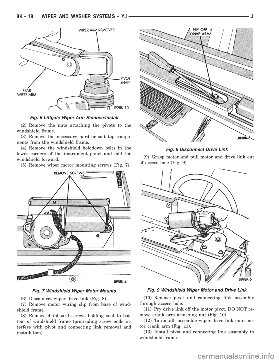
(5) Remove wiper motor mounting screws (Fig. 7).
(6) Disconnect wiper drive link (Fig. 8).
(7) Remove motor wiring clip from base of wind-
shield frame.
(8) Remove 4 inboard screws holding seal to bot-
tom of windshield frame (protruding screw ends in-
terfere with pivot and connecting link removal and
installation).(9) Grasp motor and pull motor and drive link out
of access hole (Fig. 9).
(10) Remove pivot and connecting link assembly
through access hole.
(11) Pry drive link off the motor pivot. DO NOT re-
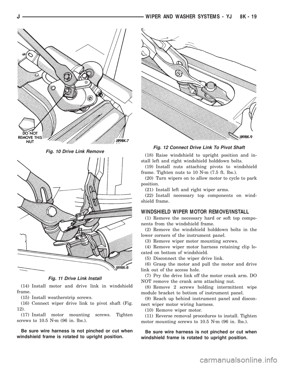
move crank arm attaching nut (Fig. 10).
(12) To install, assemble wiper drive link onto mo-
tor crank arm (Fig. 11).
(13) Install pivot and connecting link assembly in
windshield frame.
Fig. 6 Liftgate Wiper Arm Remove/Install
Fig. 7 Windshield Wiper Motor Mounts
Fig. 8 Disconnect Drive Link
Fig. 9 Windshield Wiper Motor and Drive Link
8K - 18 WIPER AND WASHER SYSTEMS - YJJ
Page 453 of 2158
(14) Install motor and drive link in windshield
frame.
(15) Install weatherstrip screws.
(16) Connect wiper drive link to pivot shaft (Fig.
12).
(17) Install motor mounting screws. Tighten
screws to 10.5 Nzm (96 in. lbs.).
Be sure wire harness is not pinched or cut when
windshield frame is rotated to upright position.(18) Raise windshield to upright position and in-
stall left and right windshield holddown bolts.
(19) Install nuts attaching pivots to windshield
frame. Tighten nuts to 10 Nzm (7.5 ft. lbs.).
(20) Turn wipers on to allow motor to cycle to park
position.
(21) Install left and right wiper arms.
(22) Install necessary top components on wind-
shield frame.
WINDSHIELD WIPER MOTOR REMOVE/INSTALL
(1) Remove the necessary hard or soft top compo-
nents from the windshield frame.
(2) Remove the windshield holddown bolts in the
lower corners of the instrument panel.
(3) Remove wiper motor mounting screws.
(4) Remove wiper motor harness retaining clip lo-
cated on bottom of windshield.
(5) Disconnect the wiper drive link.
(6) Grasp the motor and pull the motor and drive
link out of the access hole.
(7) Pry the drive link off the motor crank arm. DO
NOT remove the crank arm attaching nut.
(8) Remove 2 screws holding intermittent wipe
module bracket to bottom of instrument panel.
(9) Reach up behind instrument panel and discon-
nect wiper motor wiring harness.
(10) Remove wiper motor.
(11) Reverse removal procedures to install. Tighten
motor mounting screws to 10.5 Nzm (96 in. lbs.).
Be sure wire harness is not pinched or cut when
windshield frame is rotated to upright position.
Fig. 10 Drive Link Remove
Fig. 11 Drive Link Install
Fig. 12 Connect Drive Link To Pivot Shaft
JWIPER AND WASHER SYSTEMS - YJ 8K - 19
Page 461 of 2158

LAMPS
CONTENTS
page page
BULB APPLICATIONÐXJ VEHICLES......... 18
GENERAL INFORMATION.................. 1INTERIOR LAMPS....................... 16
SERVICE PROCEDURES................... 6
GENERAL INFORMATION
Each vehicle is equipped with various lamp assem-
blies. A good ground is necessary for proper lighting
operation. Grounding is provided by the lamp socket
when it comes in contact with the metal body, or
through a separate ground wire.
When changing lamp bulbs check the socket for
corrosion. If corrosion is present, clean it with a wire
brush and coat the inside of the socket lightly with
Mopar Multi-Purpose Grease or equivalent.
DIAGNOSTIC PROCEDURESÐXJ
When a vehicle experiences problems with the
headlamp system, verify the condition of the batteryconnections, charging system, headlamp bulbs, wire
connectors, relay, high beam dimmer switch and
headlamp switch. Refer to Group 8W, Wiring Dia-
grams for component locations and circuit informa-
tion.
Always begin any diagnosis by testing all of the
fuses and circuit breakers in the system. Refer to
Group 8W, Wiring Diagrams.
JLAMPS 8L - 1
Page 471 of 2158
INSTALLATION
(1) Squeeze the tabs on the side of the fog lamp
switch and insert the switch in the instrument panel
cavity.
(2) Connect the wire harness connector to the
switch.
(3) Install the fog lamp switch cover.
(4) Position the bezel on the instrument panel and
install the attaching screws. Tighten the screws se-
curely.
MULTI-FUNCTION SWITCH SERVICE
PROCEDURESÐXJ
REMOVAL
(1) Disconnect battery negative cable.
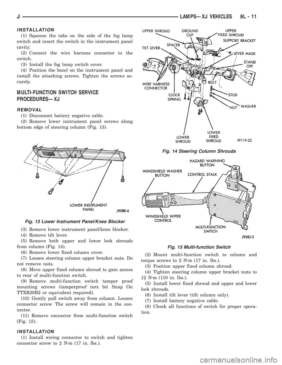
(2) Remove lower instrument panel screws along
bottom edge of steering column (Fig. 13).
(3) Remove lower instrument panel/knee blocker.
(4) Remove tilt lever.
(5) Remove both upper and lower lock shrouds
from column (Fig. 14).
(6) Remove lower fixed column cover.
(7) Loosen steering column upper bracket nuts. Do
not remove nuts.
(8) Move upper fixed column shroud to gain access
to rear of multi-function switch.
(9) Remove multi-function switch tamper proof
mounting screws (tamperproof torx bit Snap On
TTXR20B2 or equivalent required).
(10) Gently pull switch away from column. Loosen
connector screw. The screw will remain in the con-
nector.
(11) Remove connector from multi-function switch
(Fig. 15).
INSTALLATION
(1) Install wiring connector to switch and tighten
connector screw to 2 Nzm (17 in. lbs.).(2) Mount multi-function switch to column and
torque screws to 2 Nzm (17 in. lbs.).
(3) Position upper fixed column shroud.
(4) Tighten steering column upper bracket nuts to
12 Nzm (110 in. lbs.).
(5) Install lower fixed shroud and upper and lower
lock shrouds.
(6) Install tilt lever (tilt column only).
(7) Install battery negative cable.
(8) Check all functions of switch for proper opera-
tion.
Fig. 13 Lower Instrument Panel/Knee Blocker
Fig. 14 Steering Column Shrouds
Fig. 15 Multi-function Switch
JLAMPSÐXJ VEHICLES 8L - 11
Page 479 of 2158

LAMPS
CONTENTS
page page
BULB APPLICATIONÐYJ VEHICLES......... 32
GENERAL INFORMATION................. 19INTERIOR LAMPS....................... 31
SERVICE PROCEDURES.................. 22
GENERAL INFORMATION
Each vehicle is equipped with various lamp assem-
blies. A good ground is necessary for proper lighting
operation. Grounding is provided by the lamp socket
when it comes in contact with the metal body, or
through a separate ground wire.
When changing lamp bulbs check the socket for
corrosion. If corrosion is present, clean it with a wire
brush and coat the inside of the socket lightly with
Mopar Multi-Purpose Grease or equivalent.
DIAGNOSTIC PROCEDURESÐYJ
When a vehicle experiences problems with the
headlamp system, verify the condition of the batteryconnections, charging system, headlamp bulbs, wire
connectors, relay, high beam dimmer switch and
headlamp switch. Refer to Group 8W, Wiring Dia-
grams for component locations and circuit informa-
tion.
Always begin any diagnosis by testing all of the
fuses and circuit breakers in the system. Refer to
Group 8W, Wiring Diagrams.
JLAMPSÐYJ VEHICLES 8L - 19